DirectX-Specs
Conservative Rasterization
Version: 3.2
Date: 6/30/2015
Contents
- Summary
- Overview
- Interactions with the Pipeline
- Rasterization Rules interaction
- Multisampling interaction
- SampleMask interaction
- Depth/Stencil Test interaction
- Helper Pixel interaction
- Output Coverage interaction
- InputCoverage interaction
- InnerCoverage
- Attribute Interpolation interaction
- Clipping interaction
- Clip Distance interaction
- Target Independent Rasterization interaction
- IA Primitive Topology interaction
- Query interaction
- Cull State interaction
- IsFrontFace interaction
- Fill Modes interaction
- Tiered Support
- API Changes
- DDI Design
- Runtime Changes
- Functional / Unit Tests
- Questions
Summary
Support Conservative Rasterization in Direct3D. Conservative Rasterization is mode of operation for the Rasterizer stage of the Direct3D Graphics Pipeline. It disables the standard sample-based rasterization, and will instead rasterize a pixel that is covered by any amount by a primitive. One important distinction is that, while any coverage at all produces a rasterized pixel, that coverage cannot be characterized by the hardware so coverage always appears binary to a Pixel Shader: either fully covered or not covered. It is left to the Pixel Shader code to analytically determine the actual coverage, if needed.
Overview
Conservative Rasterization in this context means that all pixels that are at least partially covered by a rendered primitive are rasterized, meaning the Pixel Shader is invoked. Behavior is not dependent on the sample point coverage that is used when Conservative Rasterization is not enabled: if any part of a primitive overlaps a pixel, then that pixel is considered covered and is then rasterized. When an edge or corner of a primitive falls along the edge or corner of a pixel, the application of the Top-Left Rule is implementation-specific (with the exception of implementations using the minimum uncertainty region). However, for implementations that support degenerate triangles, a degenerate triangle along an edge or corner must cover at least one pixel; so nothing falls through the cracks.
This type of rasterization is sometimes referred to as Overestimated Conservative Rasterization. There is also the concept of Underestimated Conservative Rasterization, which means that only pixels that are fully covered by a rendered primitive are rasterized. Underestimated Conservative Rasterization is only exposed via the new InnerCoverage System Generated Value, described later. The D3D Rasterizer’s Conservative Rasterization mode specified here is only Overestimated Conservative Rasterization.
Conservative Rasterization implementations are allowed to produce false positives, meaning they incorrectly decide that pixels are covered. This can happen due to implementation-specific details like primitive growing or snapping error inherent in the fixed-point vertex coordinates used in rasterization. The reason false positives (with respect to fixed point vertex coordinates) are valid is because some amount of false positives are needed to allow an implementation to do coverage evaluation against post-snapped vertices (i.e. vertex coordinates that have been converted from floating point to the 16.8 fixed-point used in the Rasterizer), but honor the coverage produced by the original floating point vertex coordinates. Beyond that, implementations are encouraged to reduce the number of false positives as much as possible. Limits on false positives are detailed in Rasterization Rules interaction.
Conservative Rasterization implementations must never produce false negatives with respect to the floating-point vertex coordinates for non-degenerate post-snap primitives: if any part of a primitive overlaps any part of a pixel, then that pixel must be rasterized.
Triangles that are degenerate (duplicate indices in an index buffer or collinear in 3D), or become degenerate after fixed-point conversion (collinear vertices in the Rasterizer), may or may not be culled; both are valid behaviors. However, Tier 2 and above require an implementation to never produce false negatives with respect to the floating-point vertex coordinates and therefore they must rasterize degenerates, with the exception that triangles with duplicate indices in an index buffer may be culled (some hardware automatically discards triangles with duplicate indices and this case is not considered useful enough to force a hardware change). Degenerate triangles must be considered back facing, so if a specific behavior is required by an application, it can use back-face culling or the IsFrontFace System Generated Value. Degenerate triangles must use the values assigned to Vertex 0 for all interpolated values.
Conservative Rasterization is an optional feature as of D3D11.3. (Note: check support DDI not detailed here). A WDDM 2.0+, D3D Feature Level 11.1+ capable driver and hardware is required.
Conservative Rasterization support will be defined by three Tiers, as described in the Tiered Support section.
Architectural Overview
Conservative Rasterization will only be supported on WDDM 2.0 or newer UMDs that support FL11.1+. A new capability bit will expose support on such systems.
Architecture Decisions
We will use a Tiered structure to split implementations across two differentiators: post-snap degenerate culling behavior, and inner input coverage.
(1) Tier 1:
- ½ pixel uncertainty region, and no post-snap degenerates
- Good for tiled rendering, texture atlas, light map gen, sub-pixel shadow maps
(2) Tier 2:
- Adds post-snap degenerates, and 1/256 uncertainty region
- Adds support for CPU-based-algorithm acceleration (e.g. voxelization)
(3) Tier 3:
- Adds Inner input coverage
- Adds support for occlusion culling
Interactions with the Pipeline
Rasterization Rules interaction
In Conservative Rasterization mode, Rasterization Rules apply the same way as when Conservative Rasterization mode is not enabled with exceptions for the Top-Left Rule, as described previously, and [Pixel Coverage]{.underline}. 16.8 Fixed-Point Rasterizer precision must be used.
Pixels that would not be covered if hardware was using full floating point vertex coordinates may only be included if they are within an uncertainty region no larger half a pixel in the fixed point domain. Future hardware is expected to reach the tightened uncertainty region specified in Tier 2. Note that this requirement prevents sliver triangles from extending further than necessary.
A similar valid uncertainty region applies to InnerCoverage as well, but it is tighter since no implementations require a larger uncertainty region for this case. See InnerCoverage for more detail.
Inner and outer uncertainty regions must be greater than or equal to the size of half the subpixel grid, or 1/512 of a pixel, in the fixed point domain. This is the minimum valid uncertainty region. 1/512 comes from the 16.8 fixed point Rasterizer coordinate representation and the round-to-nearest rule that applies when converting floating point vertex coordinates to 16.8 fixed point coordinates. 1/512 can change if the Rasterizer precision changes. If an implementation implements this minimum uncertainty region, then they must follow the Top-Left Rule when an edge or corner of the uncertainty region falls along the edge or corner of a pixel. The clipped edges of the uncertainty region should be treated as the closest vertex, meaning that it counts as two edges: the two that join at the associated vertex. Top-Left Rule is required when the minimum uncertainty region is used because if it is not, then a Conservative Rasterization implementation would fail to rasterize pixels that could be covered when Conservative Rasterization mode is disabled.
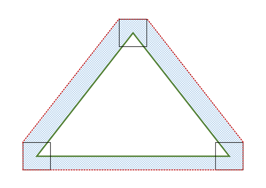
The included diagram illustrates a valid outer uncertainty region produced by sweeping a square around the edges of the primitive in the fixed point domain (i.e. the vertices have been quantized by the 16.8 fixed point representation). The dimensions of this square are based on the valid outer uncertainty region size: for the 1/2 of a pixel, the square is 1 pixel in width and height, for 1/512 of a pixel, the square is 1/256 of a pixel in width and height. The green triangle represents a given primitive, the red dotted line represents the bound on Overestimated Conservative Rasterization, the solid black squares represent the square that is swept along the primitive edges, and the blue checkered area is the outer uncertainty region:
Multisampling interaction
Regardless of the number of samples in RenderTarget/DepthStencil surfaces (or whether ForcedSampleCount is being used or not), all samples are covered for pixels rasterized by Conservative Rasterization. Individual sample locations are not tested for whether they fall in the primitive or not.
SampleMask interaction
The SampleMask Rasterizer State applies the same way as when Conservative Rasterization is not enabled for InputCoverage, but does not affect InnerCoverage (i.e. it is not AND’ed into an input declared with InnerCoverage). This is because InnerCoverage is unrelated to whether MSAA samples are masked out: 0 InnerCoverage only means that the pixel is not guaranteed to be fully covered, not that no samples will be updated.
Depth/Stencil Test interaction
Depth/Stencil Testing proceeds for a conservatively rasterized pixel the same way as if all samples are covered when Conservative Rasterization is not enabled. Proceeding with all samples covered can cause Depth extrapolation, which is valid and must be clamped to the viewport as specified when Conservative Rasterization is not enabled. This is similar to when pixel-frequency interpolation modes are used on a RenderTarget with sample count > 1 (see section 3.5.5), although in the case of Conservative Rasterization, it is the depth value going into the fixed function depth test that can be extrapolated.
Use of early depth culling behavior in combination with conservative rasterization is undefined. This includes early depth culling where depth extrapolation occurs. This is because some Early Depth culling hardware cannot properly support extrapolated depth values. However, Early Depth culling behavior in the presence of Depth Extrapolation is problematic even with hardware that can support extrapolated depth values. This issue can be worked around by clamping the Pixel Shader input depth to the min and max depth values of the primitive being rasterized and writing that value to oDepth. Implementations are required to disable Early Depth culling in this case, due to the oDepth write.
Helper Pixel interaction
Helper Pixel rules apply the same way as when Conservative Rasterization is not enabled. As part of this, all pixels including Helper Pixels must report InputCoverage accurately as specified in the InputCoverage interaction section. So fully noncovered pixels report 0 coverage.
Output Coverage interaction
Output Coverage (oMask) behaves for a conservatively rasterized pixel as it does when Conservative Rasterization is not enabled with all samples covered.
InputCoverage interaction
In Conservative Rasterization mode, this input register is populated as if all samples are covered when Conservative Rasterization is not enabled for a given conservatively rasterized pixel. That is to say, all existing interactions apply (e.g. SampleMask is applied), and the first n bits in InputCoverage from the LSB are set to 1 for a conservatively rasterized pixel, given an n sample per pixel RenderTarget and/or Depth/Stencil buffer is bound at the Output Merger, or an n sample ForcedSampleCount. The rest of the bits are 0.
This input is available in a shader regardless of the use of Conservative Rasterization, though Conservative Rasterization changes its behavior to only show all samples covered (or none for Helper Pixels).
InnerCoverage
This feature is required by, and only available in, Tier 3. The runtime will fail shader creation for shaders that use this mode when an implementation supports a Tier less than Tier 3.
The Pixel Shader has a new 32-bit scalar integer System Generate Value available: InnerCoverage. This is a bitfield that has bit 0 from the LSB set to 1 for a given conservatively rasterized pixel, only when that pixel is guaranteed to be entirely inside the current primitive. All other input register bits must be set to 0 when bit 0 is not set, but are undefined when bit 0 is set to 1 (essentially, this bitfield represents a Boolean value where false must be exactly 0, but true can be any odd (i.e. bit 0 set) non-zero value). This input is used for underestimated Conservative Rasterization information. It informs the Pixel Shader whether the current pixel lies completely inside the geometry.
This must account for snapping error at resolutions greater than or equal to the resolution at which the current Draw is operating. There must not be false positives (setting InnerCoverage bits when the pixel is not fully covered for any snapping error at resolutions greater than or equal to the resolution at which the current Draw is operating), but false negatives are allowed. Said another way, the implementation must not incorrectly identify pixels as fully covered that would not be with full floating point vertex coordinates in the Rasterizer.
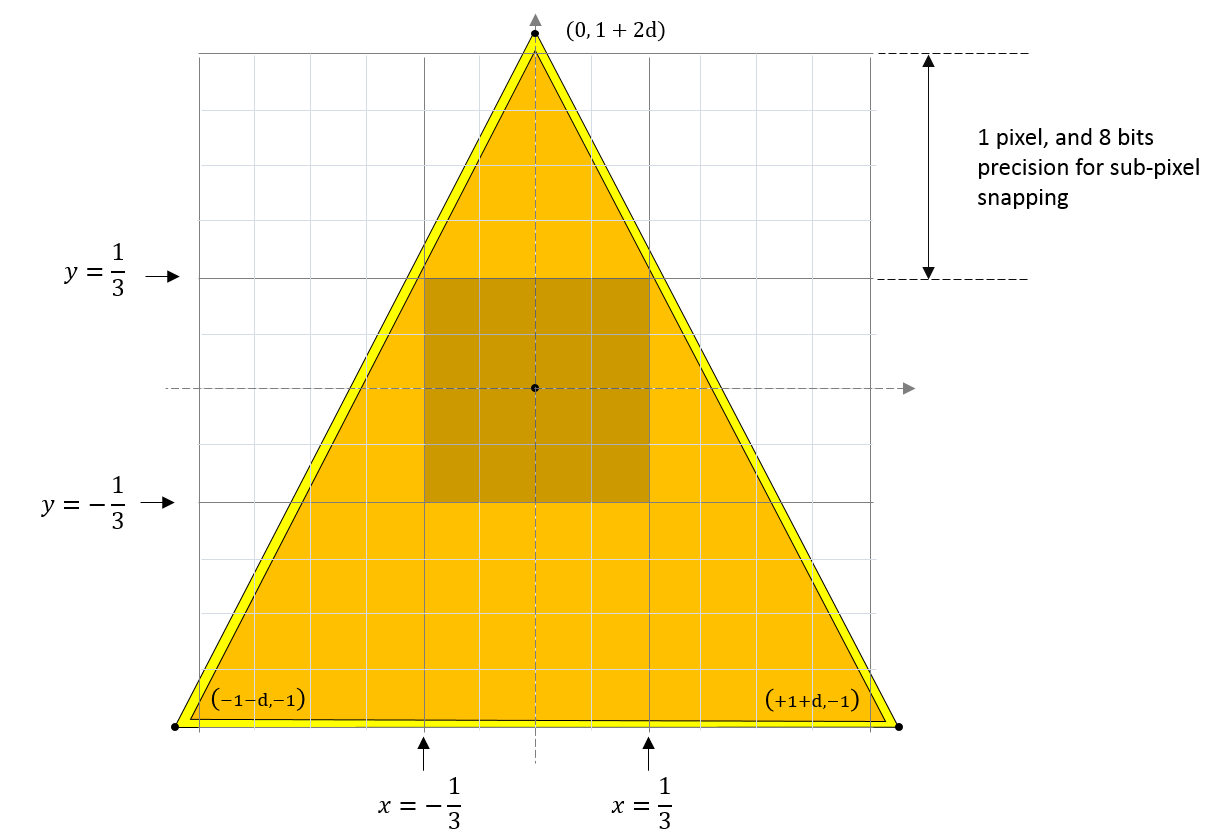
Pixels that would be fully covered if hardware was using full floating point vertex coordinates may only be omitted if they intersect the inner uncertainty region, which must be no larger than the size of the subpixel grid, or 1/256 of a pixel, in the fixed point domain. Said another way, pixels entirely within the inner boundary of the inner uncertainty region must be marked as fully covered. The inner boundary of the uncertainty region is illustrated in the diagram below by the bold black dotted line. 1/256 comes from the 16.8 fixed point Rasterizer coordinate representation, which can change if the Rasterizer precision changes. This uncertainty region is enough to account for snapping error caused by the conversion of floating point vertex coordinates to fixed point vertex coordinates in the Rasterizer.
The same 1/512 minimum uncertainty region requirements defined in Rasterization Rules interaction apply here as well.
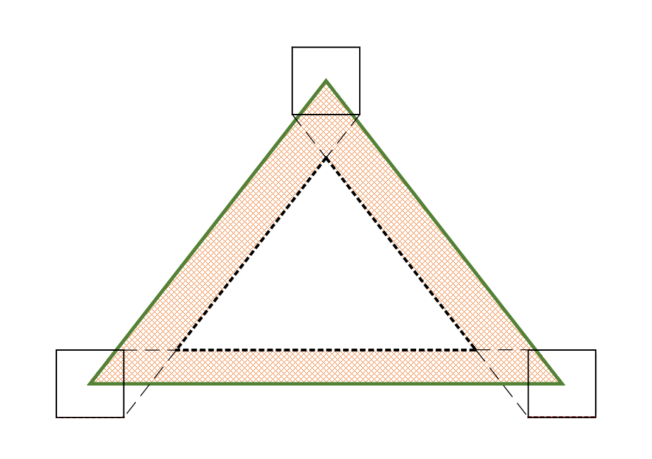
The included diagram illustrates a valid inner uncertainty region produced by sweeping a square around the edges of the primitive in the fixed point domain (i.e. the vertices have been quantized by the 16.8 fixed point representation). The dimensions of this square are based on the valid inner uncertainty region size: for 1/256 of a pixel, the square is 1/128 of a pixel in width and height. The green triangle represents a given primitive, the bold black dotted line represents the boundary of the inner uncertainty region, the solid black squares represent the square that is swept along the primitive edges, and the orange checkered area is the inner uncertainty region:
The use of InnerCoverage does not affect whether a pixel is conservatively rasterized, i.e. using one of these InputCoverage modes does not affect which pixels are rasterized when Conservative Rasterization mode is enabled. Therefore, when InnerCoverage is used and the Pixel Shader is processing a pixel that is not completely covered by the geometry its value will be 0, but the Pixel Shader invocation will have samples updated. This is different from when InputCoverage is 0, meaning that no samples will be updated.
This input is mutually exclusive with InputCoverage: both cannot be used.
To access InnerCoverage, it must be declared as a single component out of one of the Pixel Shader input registers. The interpolation mode on the declaration must be constant (interpolation does not apply).
The InnnerCoverage bitfield is not affected by depth/stencil tests, nor is it ANDed with the SampleMask Rasterizer state.
This input is only valid in Conservative Rasterization mode. That is to say, when Conservative Rasterization is not enabled, InnerCoverage produces an undefined value.
Pixel Shader invocations caused by the need for Helper Pixels, but otherwise not covered by the primitive, must have the InnerCoverage register set to 0.
Attribute Interpolation interaction
Attribute interpolation modes are unchanged and proceed the same way as when Conservative Rasterization is not enabled, where the viewport-scaled and fixed-point-converted vertices are used. Because all samples in a conservatively rasterized pixel are considered covered, it is valid for values to be extrapolated, similar to when pixel-frequency interpolation modes are used on a RenderTarget with sample count > 1 (see section 3.5.5). Centroid interpolation modes produce results identical to the corresponding non-centroid interpolation mode; the notion of centroid is meaningless in this scenario – where sample coverage is only either full or 0.
Conservative Rasterization allows for degenerate triangles to produce Pixel Shader invocations, therefore, degenerate triangles must use the values assigned to Vertex 0 for all interpolated values.
Clipping interaction
When Conservative Rasterization mode is enabled and depth clip is disabled (i.e. DepthClipEnable Rasterizer State set to FALSE), there may be variances in attribute interpolation for segments of a primitive that fall outside the 0 <= z <= w range, depending on implementation: either constant values are used from a point where the primitive intersects the relevant plane (near or far), or attribute interpolation behaves as when Conservative Rasterization mode is disabled. However, the depth value behavior is the same regardless of Conservative Rasterization mode, i.e. primitives that fall outside of the depth range must still be given the value of the nearest limit of the viewport depth range. Attribute interpolation behavior inside the 0 <= z <= w range must remain unchanged.
Clip Distance interaction
Clip Distance is valid when Conservative Rasterization mode is enabled, and behaves for a conservatively rasterized pixel as it does when Conservative Rasterization is not enabled with all samples covered.
Note that Conservative Rasterization can cause extrapolation of the W vertex coordinate, which may cause W <= 0. This could cause per-pixel Clip Distance implementations to operate on a Clip Distance that has been Perspective Divided by an invalid W value. Clip Distance implementations must guard against invoking rasterization for pixels where vertex coordinate W <= 0 (e.g. due to extrapolation when in Conservative Rasterization mode).
Target Independent Rasterization interaction
Conservative Rasterization mode is compatible with TIR. TIR rules and restrictions apply, behaving for a conservatively rasterized pixel as if all samples are covered.
IA Primitive Topology interaction
Conservative Rasterization is not defined for line or point primitives. Therefore, Primitive Topologies that specify points or lines produce undefined behavior if they are fed to the rasterizer unit when Conservative Rasterization is enabled.
Note: there will be debug layer validation to verify applications do not use these Primitive Topologies.
Query interaction
For a conservatively rasterized pixel, D3D11 Queries must behave as they do when Conservative Rasterization is not enabled when all samples are covered. E.g. For a conservatively rasterized pixel, D3D11_QUERY_OCCLUSION and D3D11_QUERY_DATA_PIPELINE_STATISTICS must behave as they would when Conservative Rasterization is not enabled when all samples are covered.
For example, Pixel Shader invocations should increment for every conservatively rasterized pixel in Conservative Rasterization mode.
Cull State interaction
All Cull States are valid in Conservative Rasterization mode and follow the same rules as when Conservative Rasterization is not enabled.
Note: When comparing Conservative Rasterization across resolutions to itself or without Conservative Rasterization enabled, there is the possibility that some primitives may have mismatched facedness (i.e. one back facing, the other front facing). Applications can avoid this uncertainty by using D3D11_CULL_NONE and not using the IsFrontFace System Generated Value.
IsFrontFace interaction
The IsFrontFace System Generated Value is valid to use in Conservative Rasterization mode, and follows the behavior defined when Conservative Rasterization is not enabled.
Note: see cull state interaction.
Fill Modes interaction
The only valid Fill Mode for Conservative Rasterization is D3D11_FILL_SOLID, any other Fill Mode is an invalid parameter for the Rasterizer State.
This is because D3D11 functional specification specifies that wireframe Fill Mode should convert triangle edges to lines and follow the line rasterization rules and conservative line rasterization behavior has not been defined. If conservative line rasterization behavior is defined in the future, this restriction can be lifted.
Tiered Support
We expect future implementations to converge on support for Tier 3.
Tier 1
This tier captures use cases that don’t rely on degenerates being rasterized or inner coverage.
Conservative Rasterization behaves as specified previously in this document.
Tier 2
This tier captures use cases that rely on degenerates being rasterized, such as voxelization.
Conservative Rasterization behaves as specified previously in this document, with the following new requirements:
Degenerate Triangle Culling
Conservative Rasterization must not fail to rasterize pixels that would be rasterized with full floating point vertex coordinates in the Rasterizer (note that (especially post-snap) degenerate culling prevents this from being true).
Therefore, degenerate triangles must not be culled, with the exception that triangles with duplicate indices may be culled. This simplifies the distinction between Standard and Conservative Rasterization: standard always has degenerate culling, conservative does not.
Note that degenerate triangles must be back-facing, so if a specific behavior is required by an application, it can use back-face culling or the IsFrontFace System Generated Value.
Smaller Outer Uncertainty Region
Pixels that would not be covered if hardware was using floating point vertex coordinates must only be included if they are within an outer uncertainty region no larger than the size the subpixel grid, or 1/256 of a pixel as the Rasterizer exists today, in the fixed point domain. 1/256 comes from the 16.8 fixed point Rasterizer coordinate representation, which can change if the Rasterizer precision changes. This uncertainty region is enough to account for snapping error caused by the conversion of floating point vertex coordinates to fixed point vertex coordinates in the Rasterizer. Note that this requirement prevents sliver triangles from extending further than necessary.
The previously included outer uncertainty region diagram illustrates this smaller valid outer uncertainty region when the swept square measures 1/128 of a pixel in width and height.
Tier 3
This tier captures use cases that require inner input coverage, such as occlusion culling.
Conservative Rasterization behaves as specified previously in this document (including previous tier requirements), with the following new requirements:
Inner-Conservative Coverage System Generated Value
InnerCoverage System Generate Value is required.
API Changes
D3D11
A new Rasterizer Desc struct will be required at the API.
API Struct:
typedef struct D3D11_RASTERIZER_DESC2
{
    /* Previous members */
    D3D11_CONSERVATIVE_RASTER_MODE ConservativeRaster;
} D3D11_RASTERIZER_DESC2;

```C++
typedef enum D3D11_CONSERVATIVE_RASTERIZER_MODE
{
    D3D11_CONSERVATIVE_RASTER_MODE_OFF = 0; // Default
    D3D11_CONSERVATIVE_RASTER_MODE_ON = 1;
} D3D11_CONSERVATIVE_RASTERIZER_MODE;

This needs an associated CD3D11_RASTERIZER_DESC2 utility class.

A new ID3D11Device* function will be added to the latest ID3D11Device*
interface (e.g. ID3D11Device3) that takes the new desc:

```C++
HRESULT CreateRasterizerState2(
    [annotation(\"_In_\")[ const D3D11_RASTERIZER_DESC2* pRasterizerDesc,
    [annotation(\"_Out_opt_\")[ ID3D11RasterizerState2** ppRasterizerState );
A new Rasterizer State interface will be required to support a new GetDesc:
interface ID3D11RasterizerState2 : ID3D11RasterizerState1
{
    void GetDesc2( [annotation(\"_Out_\")[ D3D11_RASTERIZER_DESC2* pDesc );
};
RS[Set/Get[State() APIs do not require changes.
D3D12
D3D12 uses the same (or similar) types and interfaces, so essentially the same D3D11 changes can be made to D3D12. There is a possibility that we rename the rasterizer state interface to ID3D12RasterizerState, or that we get rid of separate pipeline objects all together and only have PSOs, but that work is being considered as part of the 11on12 effort.
HLSL
A new Input Coverage System Generated Value is defined that must work in D3D11 and D3D12:
SV_InnerCoverage
A 32-bit scalar integer that can be specified on input of a pixel shader. Requires ps_5_0 or higher.
Represents underestimated conservative rasterization information (i.e. whether a pixel is guaranteed-to-be-fully covered).
This System Generated Value is required for Tier 3 support, and is only available in that Tier. Therefore, a new Shader Feature flag must be added to the SShaderFeatureInfo FeatureFlags in order for runtime to properly validate. This is typically performed as part of the HLSL compiler work, see SHADER_FEATURE_TILED_RESOURCES as an example.
SV_InnerCoverage is mutually exclusive with SV_Coverage: both cannot be used.
To access SV_InnerCoverage, it must be declared as a single component out of one of the Pixel Shader input registers. The interpolation mode on the declaration must be constant (interpolation does not apply).
DDI Design
Conservative Rasterization will be supported by D3D11 and D3D12. D3D11 DDI is specified here, but there will be D3D12 equivalents.
D3D Feature Level 11.1+ hardware and WDDM 2.0+ UMD is required.
GetCaps
A new D3D10_2DDICAPS_TYPE will be added to communicate Tier, for example:
typedef enum D3D10_2DDICAPS_TYPE
{
    /* other caps */
    D3DWDDM2_0DDICAPS_D3D11_OPTIONS2 = 140,
} D3D10_2DDICAPS_TYPE;
And an associated struct for the driver to fill out:
// D3DWDDM2_0DDICAPS_D3D11_OPTIONS2
typedef struct D3DWDDM2_0DDICAPS_D3D11_OPTIONS2_DATA
{
    /* other caps */
    D3DWDDM2_0DDI_CONSERVATIVE_RASTERIZATION_TIER
    ConservativeRasterizationTier;
} D3DWDDM2_0DDICAPS_D3D11_OPTIONS2_DATA;
And an associated enum type:
typedef enum D3DWDDM2_0DDI_CONSERVATIVE_RASTERIZATION_TIER
{
    D3DWDDM2_0DDI_CONSERVATIVE_RASTERIZATION_NOT_SUPPORTED = 0,
    D3DWDDM2_0DDI_CONSERVATIVE_RASTERIZATION_TIER_1 = 1,
    D3DWDDM2_0DDI_CONSERVATIVE_RASTERIZATION_TIER_2 = 2,
    D3DWDDM2_0DDI_CONSERVATIVE_RASTERIZATION_TIER_3 = 3,
} D3DWDDM2_0DDI_CONSERVATIVE_RASTERIZATION_TIER;
Rasterizer State Additions
A new Conservative Rasterization mode Rasterizer State will be added, for example:
typedef struct D3DWDDM2_0DDI_RASTERIZER_DESC
{
    /* other state */
    D3DWDDM2_0DDI_CONSERVATIVE_RASTERIZATION_MODE ConservativeRaster;
} D3DWDDM2_0DDI_RASTERIZER_DESC;

typedef enum D3DWDDM2_0DDI_CONSERVATIVE_RASTERIZATION_MODE
{
    D3DWDDM2_0DDI_CONSERVATIVE_RASTERIZATION_OFF = 0, // Default
    D3DWDDM2_0DDI_CONSERVATIVE_RASTERIZATION_ON = 1,
} D3DWDDM2_0DDI_CONSERVATIVE_RASTERIZATION_MODE;
This necessitates revisions of the DDIs that have Rasterizer State parameters (CalcPrivateSize and CreateRasterizerState):
typedef SIZE_T ( APIENTRY* PFND3D12DDI_CALCPRIVATERASTERIZERSTATESIZE)(
    D3D12DDI_HDEVICE, _In_ CONST D3DWDDM2_0DDI_RASTERIZER_DESC * );

typedef VOID ( APIENTRY* PFND3DWDDM2_0DDI_CREATERASTERIZERSTATE )(
    D3D12DDI_HDEVICE, _In_ CONST D3DWDDM2_0DDI_RASTERIZER_DESC *,
    D3D12DDI_HRASTERIZERSTATE, D3D12DDI_HRTRASTERIZERSTATE );
Runtime Changes
D3D11
CRasterizerState in both the runtime and SDKLayers needs to implement the new ID3D11RasterizerState2. Uses of ID3D11RasterizerState1 should be updated to ID3D11RasterizerState2 where they make sense as well, e.g. C10and11DeviceChildForVisibleClasses<>, ChildTypeFromIFace<>, CDeviceChild<>. GetDesc will be updated to have a GetDesc_Worker that provides the shared code implementation, taking a CFunctionSentinel from the callers (see CreateRasterizerStatePostValidation for an example of CFunctionSentinel passing).
CDevice in both the runtime and SDKLayers needs to implement the new Create API added to the latest ID3D11Device* interface.
-
For the SDKLayers, CreateRasterizerState1 has its own implementation of Pre and Post validation, which must be changed. We will update CDevice::CreateRasterizerStatePreValidation and CDevice::CreateRasterizerStatePostValidation to take the latest Desc, and all old versions of CreateRasterizerState in the SDKLayers will be updated to convert to the latest Desc. (CreateRasterizerState1 (and CreateRasterizerState2) will look like CreateRasterizerState when this is done)
-
For the Core Device, CreateRasterizerState_Worker will be modified to use the latest Rasterizer State Desc and Interface. Then all Rasterizer State Create calls will forward to the Worker, doing any parameter translation and ETW logging necessary. CreateRasterizerState1 should be used as a template for the worker code. This also means a new CETWEvent_ID3D11Device_CreateRasterizerState2_ETWLogger is required to log Core Device calls to CreateRasterizerState2.
SmallRasterizerStateDesc must also be updated to handle the new API and DDI structs. This utility class is used in many of the functions identified in this section to access API state and DDI state objects.
To support layered creation, a new layered creation args that inherits from SD3D11_1LayeredRasterizerStateCreationArgs is required (e.g. SD3D11_3LayeredRasterizerStateCreationArgs). This necessitates changes to the CDevice::GetLayeredChildSize, CDevice::CreateLayeredChild, CDevice::CreateRasterizerState* functions, CDevice::EnsureRSDual, and CRasterizerState::TConstructorArgs.
DDI call sites in CDevice::GetLayeredChildSize and CRasterizerState::CLS::FinalConstruct must be updated to call the latest DDI.
Device Removed stubs for D3D11’s handling of Device Removed UMD insulation and Software Deferred Context stubs are required for the new DDIs as well.
SwitchToRef.* can be safely ignored because the precedent was set to do so with the addition of D3D11_RASTERIZER_DESC1.
Validation
CCreateRasterizerStateValidator::Validate must be updated to take a D3D11_RASTERIZER_DESC2. Any Create-time validation of Conservative Rasterization must be added here. Create validation consists of the following checks:
-
Conservative Rasterization is supported by driver
-
D3D11_FILL_MODE is only D3D11_FILL_SOLID
Draw-time validation of Conservative Rasterization will be placed in CContext::ValidateDraw, and a new default Rasterizer State Desc will be added (i.e. a new version of c_DefaultRasterizerDesc1). Draw-time validation consists of the following checks:
-
Primitive Topology is not one that produces points or lines (i.e. LINE & POINT topologies)
-
Pixel Shader is not using InnerCoverage when ConsRas is disabled.
Pixel Shader creation validation will be placed in CCreatePixelShaderValidator::ValidateShader. Validation consists of the following checks:
- Inner Coverage Feature Flag (see HLSL section) is only set if driver Tier >= Tier 3.
D3D12
Most changes specified in D3D11 apply here, with a few additions:
-
PipelineSubobjectTraits<CRasterizerState> will be updated to use D3D11_RASTERIZER_DESC2
-
c_12DefaultRasterizerDesc1 will be removed since c_12DefaultRasterizerDesc + CreateRasterizerState() fill in defaults for the missing parameters already
-
PSONeutralBlob will be updated to use D3D11_RASTERIZER_DESC2
We specify “most changes” because D3D12 is currently in the process of removing now-out-dated 11 APIs. For example, CreateRasterizerState will not have so many variants in D3D12.
Any chance to share code between D3D12 and D3D11 should be taken. To do so, the easiest way is to add a new <filename>_SharedTo11.<fileext> file that contains the shared code and is included in both D3D12 and D3D11 versions of <filename>. Let the preprocessor do the work! However, we must be mindful of changes to the DDI in D3D12 that could require the shared code to be unshared, so don’t waste work! A good candidate for sharing is the pre and post validation functions.
Functional / Unit Tests
The functional unit tests will be written in TAEF. Because negatives must be tested, we need D3D11 and D3D12 API tests. We must also ensure D3D11on12 works for positives. D3DDriver will be used for D3D11 DDI call verification, DDIFilter and WARP will be used for D3D12 and D3D11on12.
Functional unit tests will cover the following:
- CheckFeatureSupport:
- Check Tier reporting (no support through Tier 3) by querying ConsRas Tier cap to verify expected support and pfnGetCaps DDI calls.
- Check support negatives caused by lack of feature level and/or WDDM version requirements and verify pfnGetCaps is not called.
- CreateRasterizerState2
- Verify expected failures and debug output due to:
- Lack of Conservative Rasterization support by driver (integrate into CheckFeatureSupport test so all negative support cases are covered).
- D3D11_FILL_MODE != D3D11_FILL_SOLID
- Verify expected success and DDI calls (getprivatesize and create) when ConsRas is supported (again, integrate into CheckFeatureSupport so all Tiers are covered).
- Verify expected failures and debug output due to:
- GetDesc2 (Rasterizer State Interface)
- Verify GetDesc2 returns expected values after CreateRasterizerState2 success.
- RS[Set/Get[State
- Verify SetState DDI calls
- Verify GetState API returns expected state (compare GetDesc2 values, or possibly pointers)
- Draw-time validation
- Verify expected failures and debug output when Primitive Topology is not one that produces points or lines (i.e. LINE & POINT topologies).
- Verify expected failures and debug output when Pixel Shader is using InnerCoverage when ConsRas is enabled.
- Verify expected Draw DDI call and no debug output when rasterizer state is valid.
- Create Shader validation
- Verify expected failure and debug output when PS is using SV_InnerCoverage and driver Tier < Tier 3.
- Verify expected create pixel shader DDI call and no debug output when driver Tier >= Tier 3.
CreateRasterizerState2 and RS[Set/Get[State are the only ones required to unblock partners.
Note that is probably makes sense to combine many of these tests so, for example, successful creates can be used for later validation.
IHV-Bring-up Test
The unit test to unblock IHV development is written to rasterize a triangle that falls in between the center sample positions of a 2x2 Render Target. Enabling Conservative Rasterization must produce rasterized pixels, while disabling Conservative Rasterization must NOT rasterize pixels. The vertex coordinates should be <-1,0>,<1,0>,<0,0.5> in NDC, with a Viewport top-left of <0,0> and <2,2> width and height.
This test leverages 11on12 to get D3D12 coverage.
Conformance Tests
The following functionality is HCK (conformance) tested:
- Basic Functionality:
- IHV-Bring-up Test, described in the previous section
- Uncertainty Range:
- Tier 1 uses a ½ pixel uncertainty region. Tiers 2 and 3 are 1/256.
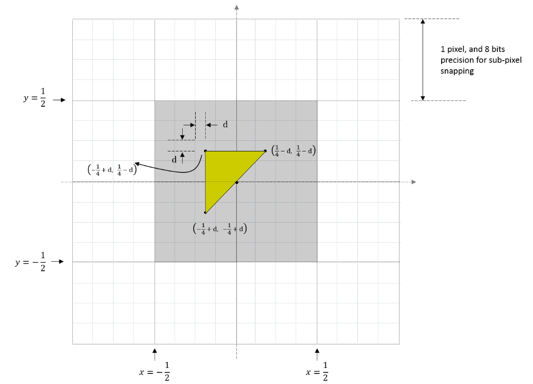
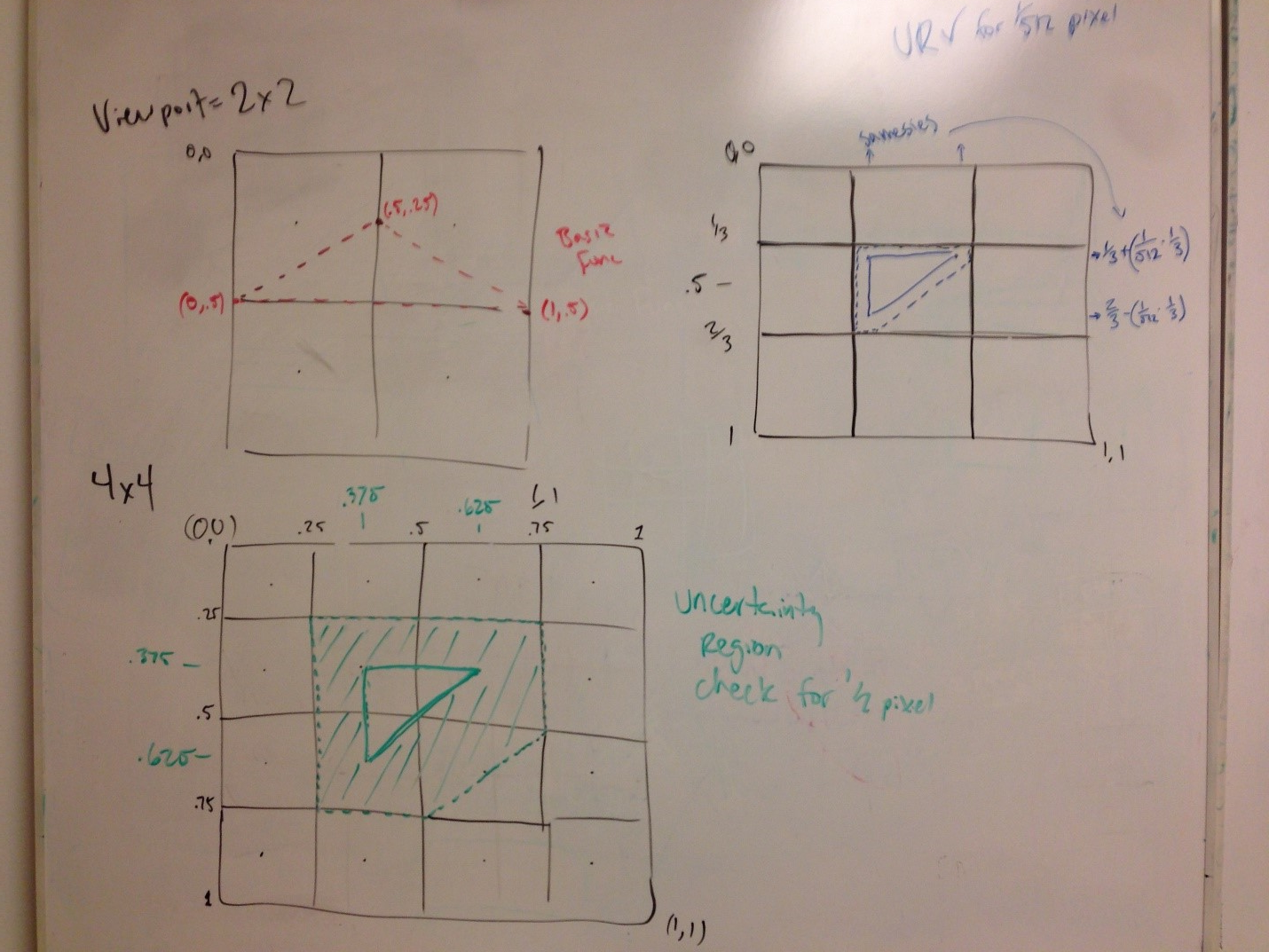
- To validate ½ pixel, a 4x4 RT/viewport will render a triangle such that only the center four pixels should be rasterized. The vertex coordinates should be <-.25+d, .25-d>,<-.25+d, -.25+d>,<.25-d, .25-d> in NDC, with a Viewport top-left of <0,0> and <4,4> width and height, where d is a small delta offset such that the uncertainty region edge does not land on a pixel edge, since Top-Left Rule is undefined.
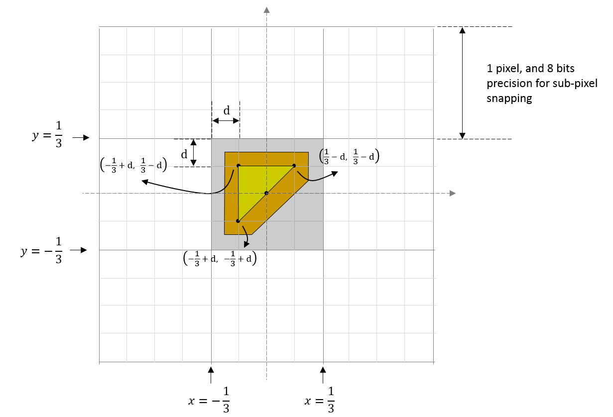
- To validate 1/256 pixel, a 3x3 RT/viewport will render a triangle such that only the center pixel should be rasterized. This test must only run when the driver reports Tier 3 support. The vertex coordinates should be <-1/3+d, 1/3-d>,<-1/3+d, -1/3+d>,<1/3-d,1/3-d> in NDC, with a Viewport top-left of <0,0> and <3,3> width and height, where d is a small delta offset accounting for the uncertainty region plus a small offset such that the uncertainty region edge does not land on a pixel edge, since Top-Left Rule is undefined.
- To validate tier-3 Top-Left Rule, we set up the primitive with vertices <-1+d, -0.5>, <d, 0.5>, and <0.5, -0.5> on a 4x4 viewport, where d is a small offset. In this case, 13 pixels should be rendered according to the Top-Left Rule. (Since the bottom-right corners of the red pixels touch the left edge of the triangle.)
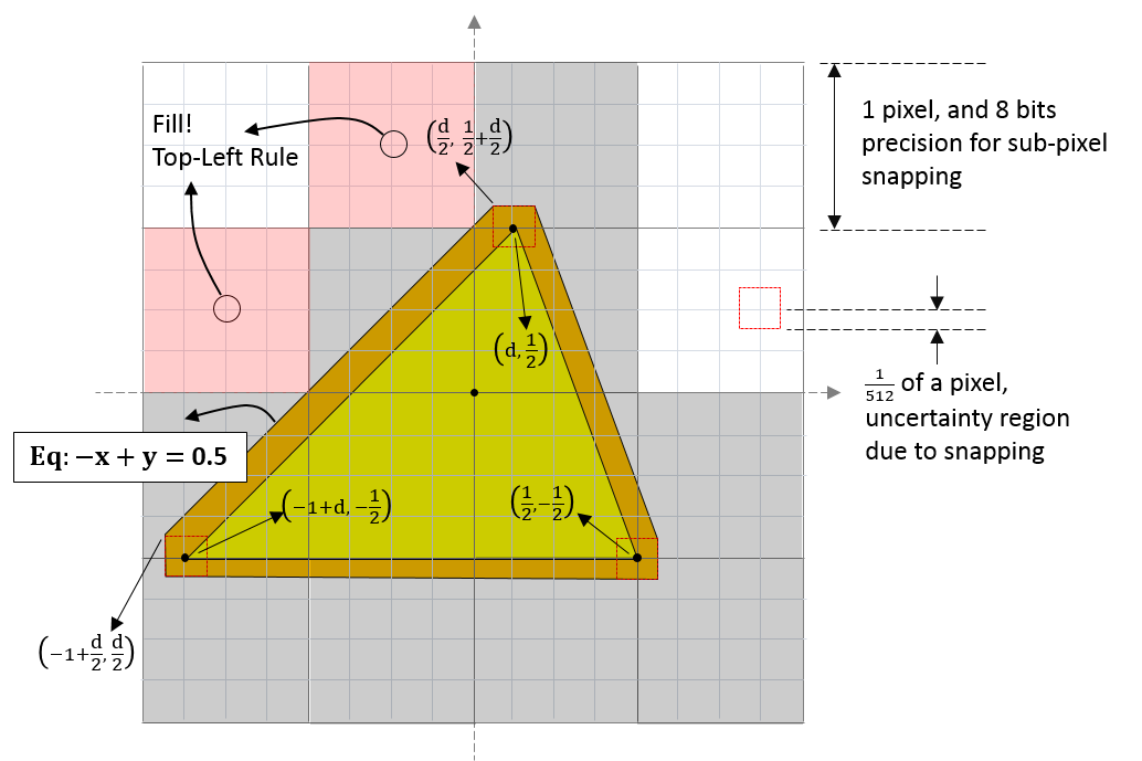
- Included below is a diagram of the described tests, but note that the actual vertex coordinate values are not in NDC:
- Inner Coverage
- Tier 3+ required.
- Ensure bits are only set when pixel is entirely within 1/256 inner uncertainty region. A 3x3 RT/Viewport is used to validate that only the center pixel receives the Inner Input Coverage flag. The vertex coordinates should be <-1-d, -1>,<1+d, -1>,<0, 1+2d> in NDC, with a Viewport top-left of <0,0> and <3,3> width and height. The value ‘d’ is chosen such that the top-left and top-right corners of the middle pixel won’t stick outside of the triangle nor will it stick into the uncertainty region.
-
Inner Input Coverage is undefined with Conservative Rasterization mode disabled, so no testing for that case.
- Post-snap degenerate culling
- Tier 1 implementations do cull, Tier 2+ implementations do not cull.
- For implementations that do not cull, a 1x3 RT/Viewport will be used to validate that a pixel is rasterized when a triangle is post-snap degenerate. The pixel must mark the triangle as back-facing, and all attributes must be V0 values. The vertex coordinates should be <-1,1>,<1,1-(1/2048)>,<1,1> in NDC, with a Viewport top-left of <0,0> and <3,1> width and height. We will assign colors of <.1,.2,.3>,<1,1,1>,<1,1,1>, respectively. The triangle must be rasterized, be back-facing, and the input color to all pixel shaders must be <.1,.2,.3>.
- For implementations that do not cull, a 1x2 RT/Viewport will be used to validate that a pixel is rasterized when a degenerate triangle falls along the pixel boundary. The vertex coordinates should be <0,-1>,<0,1>,<-1/1024,,1> in NDC, with a Viewport top-left of <0,0> and <2,1> width and height. At least one pixel must be rasterized.
- Enabling back-face culling must cull post-snap degenerates. This test will be re-run with back-face culling enabled, it should produce no rasterization.
- Other Pipeline Interactions:
- TIR
- All Tiers.
- Use IHV-Bring-up Test, modify it to set ForcedSampleCount to 4, verify that SV_Coverage receives 0x0000000F (i.e. low 4 bits set). This can be accomplished by simply writing SV_Coverage to the color output, or to a UAV.
- MSAA
- All Tiers.
- Use IHV-Bring-up Test, modify it to use 4x MSAA RT (DXGI_SAMPLE_DESC::Count = 4) and verify that SV_Coverage receives 0x0000000F (i.e. low 4 bits set).
- SampleMask w/ Inner Coverage
- Tier 3+.
- Use Inner Coverage Test, modify it to use 4x MSAA and set OMSetBlendState’s SampleMask to 0x00000000, and verify SV_InnerCoverage receives 0x00000001.
- Clip Distance
- Not interesting: clipping specification already states 0 < w requirement for Clipping, which happens before per-pixel clip distance.
- Queries (e.g. D3D11_QUERY_OCCLUSION and
D3D11_QUERY_DATA_PIPELINE_STATISTICS)
- Not interesting: low risk that Conservative Rasterization affects behavior of any Queries.
- oMask
- Not interesting: very little risk that implementations don’t use the InputCoverage as the coverage for AND’ing with oMask.
- HelperPixel coverage
- Not interesting: Helper Pixels are already tested to be non-side-effecting.
- Attribute Interpolation (extrapolation)
- Not interesting: extrapolated values already exist, no need to test them again.
- Early Z w/ Depth Extrapolation
- Not an issue for main occlusion-culling/visibility-testing techniques. All other implementations will have Early Z issues, but Qualcomm’s will be a little different.
All tests specified here can be verified by reading the Render Target contents (via copy-to-staging + map), or writing to a UAV.
Questions
- Why isn’t there an inner/under Conservative Rasterization mode?
Some Conservative Rasterization implementations are not capable of only rasterizing guaranteed-to-be-fully-covered pixels. To support the most hardware, this mode of rasterization behavior is not yet available, but the same information can be conveyed by using the InnerCoverage System Generated Value.
- Why did configurable fractional precision (versus 16.8) go away?
That feature wasn’t tightly related to Conservative Rasterization, although it can help certain use cases where Conservative Rasterization is used to render a low-resolution proxy. Conservative Rasterization should not rely on configuring the fractional precision in the rasterizer because that limits its usefulness. This feature is still interesting, and can be introduced in a future spec.