Full Table of Contents at end of document.
Chapter Contents
(back to top)
1.1 Purpose
1.2 Audience
1.3 Topics Covered
1.4 Topics Not Covered
1.5 Not Optimized for Smooth Reading
1.6 How D3D11.3 Fits into this Unified Spec
This document describes hardware requirements for Direct3D 11.3 (D3D11.3).
It is assumed that the reader is familiar with real-time graphics, modern Graphics Processing Unit (GPU) design issues and the general architecture of Microsoft Windows Operating Systems, as well their planned release roadmap.
The target audience for this spec are the implementers, testers and documenters of hardware or software components that would be considered part of a D3D11.3-compliant system. In addition, software developers who are vested in the details about medium-term GPU hardware direction will find interesting information.
Topics covered in this spec center on definition of the hardware architecture being targeted by the D3D11.1 Graphics Pipeline, in a form that attempts to be agnostic to any single vendor's hardware implementation. Included will be some references to how the Graphics Pipeline is controlled through a Device Driver Interface (DDI), and occasionally depictions of API usage as needed to illustrate points.
Occasionally, boxed text such as this appears in the spec to indicate justification for decisions, explain history about a feature, provide clarifications or general remarks about a topic being described, or to flag an unresolved issues. These shaded boxes DO NOT provide a complete listing of all such trivia, however. Note that on each revision of this spec, all changes made for that revision are summarized in a separate document typically distributed with the spec.
The exact relationship and interactions between topics covered in the Graphics Pipeline with other Operating System components is not covered.
GPU resource management, GPU process scheduling, and low-level Operating System driver/kernel architecture are not covered.
High-level GPU programming concepts (such as high level shading languages) are not covered.
Little to no theory or derivation of graphics concepts, techniques or history is provided. Equally rare for this spec is any attempt to characterize what sorts of things applications software developers might do using the functionality provided by D3D11.3. There are exceptions, but do not expect to gain much more than an understanding of the "facts" about D3D11.3 from this spec.
Beware, there is little flow to the content in this spec, although there are plenty of links from place to place.
This document is the product of starting with the full D3D11.2 functional spec and adding in relevant WindowsNext D3D11.3 features.
Each Chapter in this spec begins with a summary of the changes from D3D10 to D3D10.1 to D3D11 to D3D11.1 to D3D11.2 to D3D11.3 for that Chapter. A table of links to all of the Chapter delta summaries can be found here(25.2).
To find D3D11.3 changes specifically (which includes changes for optional new features and clarifications/corrections that affect all feature levels, look for "[D3D11.3]" in the chapter changelists (or simply search the doc for it).
Chapter Contents
(back to top)
2.1 Input Assembler (IA) Overview
2.2 Vertex Shader (VS) Overview
2.3 Hull Shader (HS) Overview
2.4 Tessellator (TS) Overview
2.5 Domain Shader (DS) Overview
2.6 Geometry Shader (GS) Overview
2.7 Stream Output (SO) Overview
2.8 Rasterizer Overview
2.9 Pixel Shader (PS) Overview
2.10 Output Merger (OM) Overview
2.11 Compute Shader (CS) Overview
Summary of Changes in this Chapter from D3D10 to D3D11.3
Back to all D3D10 to D3D11.3 changes.(25.2)
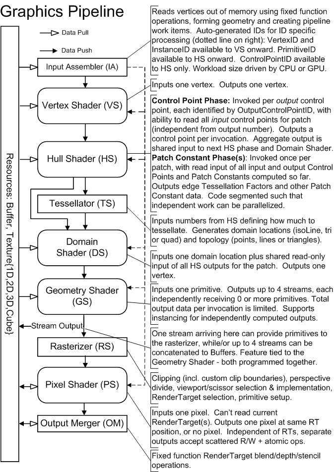
D3D11.1 hardware, like previous generations, can be designed with shared programmable cores. A farm of Shader cores exist on the GPU, able to be scheduled across the functional blocks comprising the D3D11.1 Pipeline, depicted below.
The Input Assembler (IA) introduces triangles, lines, points or Control Points (for Patches) into the graphics Pipeline, by pulling source geometry data out of 1D Buffers(5.3.4).
Vertex data can come from multiple Buffers, accessed in an "Array-of-Structures" fashion from each Buffer. The Buffers are each bound to an individual input slot and given a structure stride. The layout of data across all the Buffers is specified by an Input Declaration, in which each entry defines an "Element" with: an input slot, a structure offset, a data type, and a target register (for the first active Shader in the Pipeline).
A given sequence of vertices is constructed out of data fetched from Buffers, in a traversal directed by a combination of fixed-function state and various Draw*() API/DDI calls. Various primitive topologies are available to make the sequence of vertex data represent a sequence of primitives. Example topologies are: point-list, line-list, triangle-list, triangle-strip, 8 control-point patch-list.
Vertex data can be produced in one of two ways. The first is "Non-Indexed" rendering, which is the sequential traversal of Buffer(s) containing vertex data, originating at a start offset at each Buffer binding. The second method for producing vertex data is "Indexed" rendering, which is sequential traversal of a single Buffer containing scalar integer indices, originating at a start offset into the Buffer. Each index indicates where to fetch data out of Buffer(s) containing vertex data. The index values are independent of the characteristics of the Buffers they are referring to; Buffers are described by a declaration as mentioned earlier. So the task accomplished by "Non-Indexed" and "Indexed" rendering, each in their own way, is producing addresses from which to fetch vertex data in memory, and subsequently assemble the results into vertices and primitives.
Instanced geometry rendering is enabled by allowing the sequential traversal, in either Non-indexed or Indexed rendering, to loop over a range within each Vertex Buffer (Non-Indexed case) or Index Buffer (Indexed case). Buffer-bindings can be identified "Instance Data" or "Vertex Data", indicating how to use the bound Buffer while performing instanced rendering. The address generated by "Non-Indexed" or "Indexed" rendering is used to fetch "Vertex Data", accounting also for looping when doing Instanced rendering. "Instance Data", on the other hand, is always sequentially traversed starting from a per-Buffer offset, at a frequency equal to one step per instance (e.g. one step forward after the number of vertices in an instance are traversed). The step rate for "Instance Data" can also be chosen to be a subharmonic of the instance frequency (i.e. one step forward every other instance, every third instance etc.).
Another use of the Input Assembler is that it can read Buffers that were written to from the Stream Output(2.7) stage. Such a scenario necessitates a particular type of Draw, DrawAuto(8.9). DrawAuto enables the Input Assembler to know how much data was dynamically written to a Stream Output Buffer without CPU involvement.
In addition to producing vertex data from Buffers, the IA can auto-generate scalar counter values such as: VertexID(8.16), PrimitiveID(8.17) and InstanceID(8.18), for input to shader stages in the graphics pipeline.
In "Indexed" rendering of strip topologies, such as triangle strips, a mechanism is provided for drawing multiple strips with a single Draw*() call (i.e. 'cut'ting strips).
Specific operational details of the IA are provided here(8).
The Vertex Shader stage processes vertices, performing operations such as transformations, skinning, and lighting. Vertex Shaders always operate on a single input vertex and produce a single output vertex. This stage must always be active.
Specific operational details of Vertex Shaders are provided here(9).
The Hull Shader operates once per Patch (can only be used with Patces from the IA). It can transform input Control Points that make up a Patch into Output Control Points, and it can perform other setup for the fixed-function Tessellator stage (outputting TessFactors, which are numbers that indicate how much to tessellate).
Specific operational details of the Hull Shader are provided here(10).
The Tessellator is a fixed function unit whose operation is defined by declarations in the Hull Shader. It operates once per Patch output by the Hull Shader. The Hull shader outputs TessFactors which are numbers that tell the Tessellator how much to tessellate (generate geometry and connectivity) over the domain of the Patch.
Specific operational details of the Tessellator provided here(11).
The Domain Shader is invoked once per vertex generated by the Tessellator. Each invocation is identified by its coordinate on a generic domain, and the role of the Domain Shader is to turn that coordinate into something tangible (such as a point in 3D space) for use downstream. Each Domain Shader invocation for a Patch also sees shared input of all the Hull Shader output (such as output Control Points).
Specific operational details of the Domain Shader are provided here(12).
The Geometry Shader runs application-specified Shader code with vertices as input and the ability to generate vertices on output. The Geometry Shader's inputs are the vertices for a full primitive (two vertices for lines, three vertices for triangles, a single vertex for point, or all Control Points for a Patch if it reaches the GS with Tessellation disabled). Some types of primitives can also include the vertices of edge-adjacent primitive (an additional two vertices for a line, an additional three for a triangle).
Another input is a PrimitiveID auto-generated by the IA. This allows per-face data to be fetched or computed if desired.
The Geometry Shader stage is capable of outputting multiple vertices forming a single selected topology (GS output topologies available are: tristrip, linestrip, pointlist). The number of primitives emitted can vary freely within any invocation of the Geometry Shader, though the maximum number of vertices that could be emitted must be declared statically. Strip lengths emitted from a GS invocation can be arbitrary (there is a 'cut'(22.8.1) command).
Output may be fed to rasterizer and/or out to vertex Buffers in memory. Output fed to memory is expanded to individual point/line/triangle lists (the same way they would get passed to the rasterizer).
Algorithms that can be implemented in the Geometry Shader include:
Specific operational details of the Geometry Shader are provided here(13).
Vertices may be streamed out to memory just before arriving at the Rasterizer. This is like a "tap" in the Pipeline, which can be turned on even as data continues to flow down to the Rasterizer. Data sent out via Stream Output is concatenated to Buffer(s). These Buffers may on subsequent passes be recirculated as Pipeline inputs.
One constraint about Stream Output is that it is tied to the Geometry Shader, in that both must be created together (though either can be "NULL"/"off"). The particular memory Buffer(s) being Streamed out are not tied to this GS/SO pair though. Only the description of which parts of vertex data to feed to Stream Output are tied to the GS.
One use for Stream Output is for saving ordered Pipeline data that will be reused. For example a batch of vertices might be "skinned" by passing the vertices into the Pipeline as if they are independent points (just to visit all of them once), applying "skinning" operations on each vertex, and streaming out the results to memory. The saved out "skinned" vertices are now available for use in subsequent passes as input.
Since the amount of output written through Stream Output can be unpredictably dynamic, a special type of Draw command, DrawAuto(8.9), is necessary. DrawAuto enables the Input Assembler to know how much data was dynamically written to a Stream Output Buffer without CPU involvement. In addition, Queries are necessary to mitigate Stream Output overflow(20.4.10), as well as retrieve how much data was written(20.4.9) to the Stream Output Buffers.
Specific operational details of the Stream Output are provided here(14).
The rasterizer is responsible for clipping, primitive setup, and determining how to invoke Pixel Shaders. D3D11.3 does not view this as a "stage" in the Pipeline, but rather an interface between Pipeline stages which happens to perform a significant set of fixed function operations, many of which can be adjusted by software developers.
The rasterizer always assumes input positions are provided in clip-space, performs clipping, perspective divide and applies viewport scale/offset.
Specific operational details of the Rasterizer are provided here(15).
Input data available to the Pixel Shader includes vertex attributes that can be chosen, on a per-Element basis, to be interpolated with or without perspective correction, or be treated as constant per-primitive.
The Pixel Shader can also be chosen to be invoked either once per pixel or once per covered sample within the pixel.
Outputs are one or more 4-vectors of output data for the current pixel or sample, or no color (if pixel is discarded).
The Pixel Shader has some other inputs and outputs available as well, similar to the kind of inputs and outputs the Compute Shader can use, allowing, for instance, the ability to write to scattered locations.
Specific operational details of Pixel Shaders are provided here(16).
The final step in the logical Pipeline is visibility determination, through stencil or depth, and writing or blending of output(s) to RenderTarget(s), which may be one of many Resource Types(5).
These operations, as well as the binding of output resources (RenderTargets), are defined at the Output Merger.Specific operational details of the Output Merger are provided here(17).
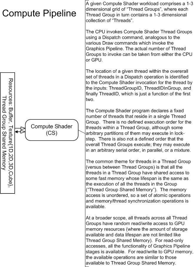
The Compute Shader allows the GPU to be viewed as a generic grid of data-parallel processors, without any graphics baggage from the graphics pipeline. The Compute Shader has explicit access to fast shared memory to facilitate communication between groups of shader invocations, and the ability to perform scattered reads and writes to memory. The availablility of atomic operations enables unique access to shared memory addresses. The Compute Shader is not part of the Graphics Pipeline (all the previously discussed shader stages). The Compute Shader exists on its own, albeit on the same device as all the other Shader Stages. To invoke this shader, Dispatch*() APIs are called instead of Draw*().
Specific operational details of Compute Shaders are provided here(18).
Chapter Contents
(back to top)
3.1 Floating Point Rules
3.2 Data Conversion
3.3 Coordinate Systems
3.4 Rasterization Rules
3.5 Multisampling
Summary of Changes in this Chapter from D3D10 to D3D11.3
Back to all D3D10 to D3D11.3 changes.(25.2)
Section Contents
(back to chapter)
3.1.1 Overview
3.1.2 Term: Unit-Last-Place (ULP)
3.1.3 32-bit Floating Point
D3D11 supports several different floating point representations for storage. However, all floating point computations in D3D11, whether in Shader programs written by application developers or in fixed function operations such as texture filtering or RenderTarget blending, are required to operate under a defined subset of the IEEE 754 32-bit single precision floating point behavior.
One ULP is the smallest representable delta from one value in a numeric representation to an adjacent value. The absolute magnitude of this delta varies with the magnitude of the number in the case of a floating point number. If, hypothetically, the result of an arithmetic operation were allowed to have a tolerance 1 ULP from the infinitely precise result, this would allow an implementation that always truncated its result (without rounding), resulting in an error of at most one unit in the last (least significant) place in the number representation. On the other hand, it would be much more desirable to require 0.5 ULP tolerance on arithmetic results, since that requires the result be the closest possible representation to the infinitely precise result, using round to nearest-even.
Here is a summary of expected 32-bit floating point behaviors for D3D11. Some of these points choose a single option in cases where IEEE-754 offers choices. This is followed by a listing of deviations or additions to IEEE-754 (some of which are significant). Refer to IEEE-754 for topics not mentioned.
Double-precision floating-point support is optional, however all double-precision floating point instructions listed in this spec (here (arithmetic)(22.14), here (conditional)(22.15), here (move)(22.16) and here (type conversion)(22.17) ) must be implemented if double support is enabled.
Double-precision floating-point usage is indicated at compile time by declaring shadel model 5_a. Support for Shader Model 5.0a will be reportable by drivers and discoverable by users via an API.
When supported, double-precision instructions match IEEE 754R behavior requirements (with the exception of double precision reciprocal(22.14.5) which is permitted 1.0 ULP tolerance and the exact result if representable).
An exception to the 4-vector register convention exists for double-precision floating-point instructions, which operate on pairs of doubles. Double-precision floating-point values are in IEEE 754R format. One double is stored in .xy with the least significant 32 bits in x, and the most significant 32 bits in y. Similarly the second double is stored in .zw with the least significant 32 bits in z, and the most significant 32 bits in w.
The permissible swizzles for double operations are .xyzw, .xyxy, .zwxy, .zwzw. The permissible write masks for double operations are .xy, .zw, and .xyzw.
Support for generation of denormalized values is required for double-precision data (no flush-to-zero behavior). Likewise, instructions do not read denormalized data as a signed zero - they honor the denorm value.
Several resource formats in D3D11 contain 16-bit representations of floating point numbers. This section describes the float16 representation.
Format:
A float16 value, v, made from the format above takes the following meaning:
32-bit floating point rules also hold for 16-bit floating point numbers, adjusted for the bit layout described above.
The exceptions are:
A single resource format in D3D11 contains 11-bit and 10-bit representations of floating point numbers. This section describes the float11 and float10 representations.
Format:
A float11/float10 value, v, made from the format above takes the following meaning:
32-bit floating point rules also hold for 11-bit and 10-bit floating point numbers, adjusted for the bit layout described above.
The exceptions are:
Section Contents
(back to chapter)
3.2.1 Overview
3.2.2 Floating Point Conversion
3.2.3 Integer Conversion
This section describes the rules for various data conversions in D3D11. Other relevant information regarding data conversion is in the Data Invertability(19.1.2) section.
Whenever a floating point conversion between different representations occurs, including to/from non-floating point representations, the following rules apply.
These are rules for converting from a higher range representation to a lower range representation:
These are rules for converting from a lower precision/range representation to a higher precision/range representation:
The following set of terms are subsequently used to characterize various integer format conversions.
| Term | Definition |
|---|---|
| SNORM | Signed normalized integer, meaning that for an n-bit 2's complement number, the maximum value means 1.0f (e.g. the 5-bit value 01111 maps to 1.0f), and the minimum value means -1.0f (e.g. the 5-bit value 10000 maps to -1.0f). In addition, the second-minimum number maps to -1.0f (e.g. the 5-bit value 10001 maps to -1.0f). There are thus two integer representations for -1.0f. There is a single representation for 0.0f, and a single representation for 1.0f. This results in a set of integer representations for evenly spaced floating point values in the range (-1.0f...0.0f), and also a complementary set of representations for numbers in the range (0.0f...1.0f) |
| UNORM | Unsigned normalized integer, meaning that for an n-bit number, all 0's means 0.0f, and all 1's means 1.0f. A sequence of evenly spaced floating point values from 0.0f to 1.0f are represented. e.g. a 2-bit UNORM represents 0.0f, 1/3, 2/3, and 1.0f. |
| SINT | Signed integer. 2's complement integer. e.g. an 3-bit SINT represents the integral values -4, -3, -2, -1, 0, 1, 2, 3. |
| UINT | Unsigned integer. e.g. a 3-bit UINT represents the integral values 0, 1, 2, 3, 4, 5, 6, 7 |
| FLOAT | A floating-point value in any of the representations defined by D3D11. |
| SRGB | Similar to UNORM, in that for an n-bit number, all 0's means 0.0f and all 1's means 1.0f. However unlike UNORM, with SRGB the sequence of unsigned integer encodings between all 0's to all 1's represent a nonlinear progression in the floating point interpretation of the numbers, between 0.0f to 1.0f. Roughly, if this nonlinear progression, SRGB, is displayed as a sequence of colors, it would appear as a linear ramp of luminosity levels to an "average" observer, under "average" viewing conditions, on an "average" display. For complete detail, refer to the SRGB color standard, IEC 61996-2-1, at IEC (International Electrotechnical Commission) |
Note that the terms above are also used as Format Name Modifiers(19.1.3.2), where they describe both how data is layed out in memory and what conversion to perform in the transport path (potentially including filtering) from memory to/from a Pipeline unit such as a Shader. See the Formats(19.1) section to see exactly how these names are used in the context of resource formats.
What follows are descriptions of conversions from various representations described above to other representations. Not all permutations are shown, but at least all the ones that show up in D3D11 somewhere are shown.
Unless otherwise specified for specific cases, all conversions to/from integer representations to float representations described below must be done exactly. Where float arithmetic is involved, FULL IEEE-754 precision is required (1/2 ULP(3.1.2) of the infinitely precise result), which is stricter than the general D3D11 Floating Point Rules(3.1).
Given an n-bit integer value representing the signed range [-1.0f to 1.0f], conversion to floating-point is as follows:
Given a floating-point number, conversion to an n-bit integer value representing the signed range [-1.0f to 1.0f] is as follows:
This conversion is permitted tolerance of 0.6f ULP(3.1.2) (on the integer side). This means that after converting from float to integer scale, any value within 0.6f ULP(3.1.2) of a representable target format value is permitted to map to that value. The additional Data Invertability(19.1.2) requirement ensures that the conversion is nondecreasing across the range and all output values are attainable.
Requiring exact (1/2 ULP) conversion precision is acknowledged to be too expensive.
The following is the ideal SRGB to FLOAT conversion.
This conversion will be permitted a tolerance of 0.5f ULP(3.1.2) (on the SRGB side). The procedure for measuring this tolerance, given that it is relative to the SRGB side even though the result is a FLOAT, is to convert the result back into SRGB space using the ideal FLOAT -> SRGB conversion specified below, but WITHOUT the rounding to integer, and taking the floating point difference versus the original SRGB value to yield the error. There are a couple of exceptions to this tolerance, where exact conversion is required: 0.0f and 1.0f (the ends) must be exactly achievable.
The following is the ideal FLOAT -> SRGB conversion.
Assuming the target SRGB color component has n bits:
This conversion is permitted tolerance of 0.6f ULP(3.1.2) (on the integer side). This means that after converting from float to integer scale, any value within 0.6f ULP(3.1.2) of a representable target format value is permitted to map to that value. The additional Data Invertability(19.1.2) requirement ensures that the conversion is nondecreasing across the range and all output values are attainable.
Requiring exact (1/2 ULP) conversion precision is acknowledged to be too expensive.
To convert from SINT to an SINT with more bits, the MSB bit of the starting number is "sign-extended" to the additional bits available in the target format.
To convert from UINT to an SINT with more bits, the number is copied to the target format's LSBs and additional MSB's are padded with 0.
To convert from SINT to UINT with more bits: If negative, the value is clamped to 0. Otherwise the number is copied to the target format's LSBs and additional MSB's are padded with 0.
To convert from UINT to UINT with more bits the number is copied to the target format's LSBs and additional MSB's are padded with 0.
To convert from a SINT or UINT to SINT or UINT with fewer or equal bits (and/or change in signedness), the starting value is simply clamped to the range of the target format.
Fixed point integers are simply integers of some bit size that have an implicit decimal point at a fixed location. The ubiquitous "integer" data type is a special case of a fixed point integer with the decimal at the end of the number. Fixed point number representations are characterized as: i.f, where i is the number of integer bits and f is the number of fractional bits. e.g. 16.8 means 16 bits integer followed by 8 bits of fraction. The integer part is stored in 2's complement, at least as defined here (though it can be defined equally for unsigned integers as well). The fractional part is stored in unsigned form. The fractional part always represents the positive fraction between the two nearest integral values, starting from the most negative. Exact details of fixed point representation, and mechanics of conversion from floating point numbers are provided below.
Addition and subtraction operations on fixed point numbers are performed simply using standard integer arithmetic, without any consideration for where the implied decimal lies. Adding 1 to a 16.8 fixed point number just means adding 256, since the decimal is 8 places in from the least significant end of the number. Other operations such as multiplication, can be performed as well simply using integer arithmetic, provided the effect on the fixed decimal is accounted for. For example, multiplying two 16.8 integers using an integer multiply produces a 32.16 result.
Fixed point integer representations are used in a couple of places in D3D11:
The following is the general procedure for converting a floating point number n to a fixed point integer i.f, where i is the number of (signed) integer bits and f is the number of fractional bits:
Note: Sign of zero is preserved.
For D3D11 implementations are permitted 0.6f ULP(3.1.2) tolerance in the integer result vs. the infinitely precise value n*2^f after the last step above.
The diagram below depicts the ideal/reference float to fixed conversion (including round-to-nearest-even), yielding 1/2 ULP accuracy to an infinitely precise result, which is more accurate than required by the tolerance defined above. Future D3D versions will require exact conversion like this reference.
Specific choices of bit allocations for fixed point integers are listed in the places in the D3D11 spec where they are used.
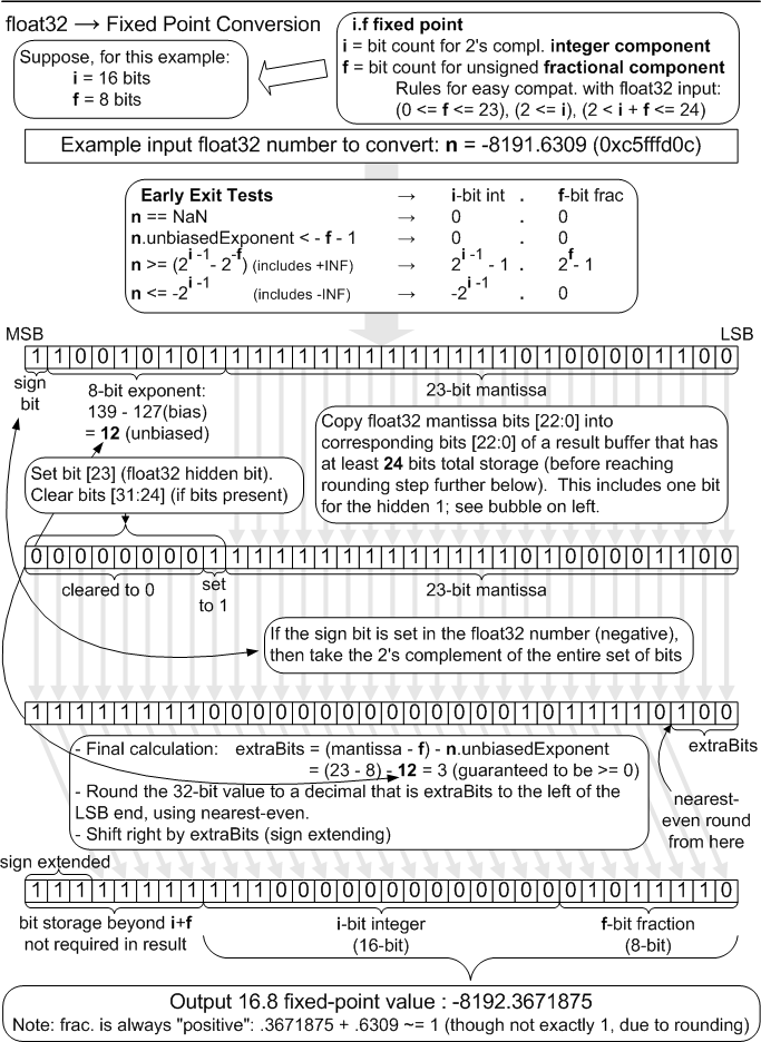
Assume that the specific fixed point representation being converted to float does not contain more than a total of 24 bits of information, no more than 23 bits of which is in the fractional component. Suppose a given fixed point number, fxp, is in i.f form (i bits integer, f bits fraction). The conversion to float is akin to the following pseudocode:
float result = (float)(fxp >> f) +              // extract integer
               ((float)(fxp & (2f - 1)) / (2f)); // extract fraction
Although the situation rarely, if ever arises, consider that a number that originates as fixed point, gets converted to float32, and then gets converted back to fixed point will remain identical to its original value. This holds provided that bit representation for the fixed point number does not contain more information than can be represented in a float32. This lossless conversion property does not hold when making the opposite round-trip, starting from float32, moving to fixed-point, and back; indeed lossy conversion is in fact the "point" of converting from float32 to fixed-point in the first place.
One final note on round-trip conversion. Observe that when the float32 number -2.75 is converted to fixed-point, it becomes -3 +0.25, that is, the integer part is negative but the fixed point part, considered by itself, is positive. When that is converted back to float32, it becomes -2.75 again, since floating point stores negative numbers in sign-magnitude form, instead of in two's complement form.
Section Contents
(back to chapter)
3.3.1 Pixel Coordinate System
3.3.2 Texel Coordinate System
3.3.3 Texture Coordinate Interpretation
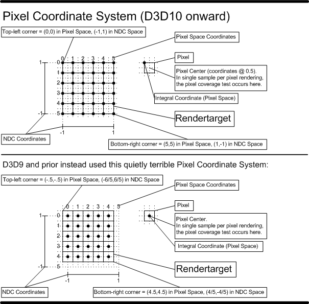
The Pixel Coordinate System defines the origin as the upper-left corner of the RenderTarget. Pixel centers are therefore offset by (0.5f,0.5f) from integer locations on the RenderTarget. This choice of origin makes rendering screen-aligned textures trivial, as the pixel coordinate system is aligned with the texel coordinate system.
D3D9 and prior had a terrible Pixel Coordinate System where the origin was the center of the top left pixel on the RenderTarget. In other words, the origin was (0.5,0.5) away from the upper left corner of the RenderTarget. There was the nice property that Pixel centers were at integer locations, but the fact this was misaligned with the texture coordinate system frequently burned unsuspecting developers. Further, with Multisample rendering, thre was a 1/2 pixel wide region of the RenderTarget along the top and left edge that the viewport could not cover. D3D11 allows applications that want to emulate this behavior to specify a fractional offset to the top left corner of the viewport (-0.5,-0.5).
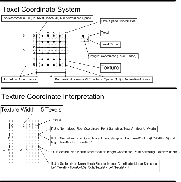
The texel coordinate system has its origin at the top-left corner of the texture. See the "Texel Coordinate System" diagram below. This is consistent with the Pixel Coordinate System.
The memory load instructions like sample(22.4.15) or ld(22.4.6) have a couple of ways texture coordinates are interpreted (normalized float, or scaled integer respectively). The "Texture Coordinate Interpretation" diagram below describes how these interpretations get mapped to specific texel(s), for point and linear sampling. The diagram does not illustrate address wrapping, which occurs after the shown equations for computing texel locations. The addressing math shown in this diagram is only a general guideline, and exact definition of texel selection arithmetic is provided in the Texture Sampling(7.18) section, including the role of Fixed Point(3.2.4.1) snapping of precision in the addressing process.
Section Contents
(back to chapter)
3.4.1 Coordinate Snapping
3.4.2 Triangle Rasterization Rules
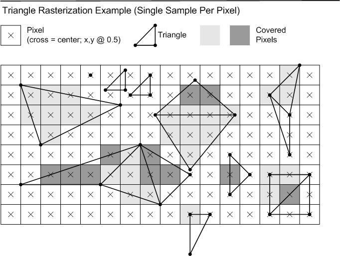
Consider a set of vertices going through the Rasterizer, after having gone through clipping, perspective divide and viewport scale. Suppose that any further primitive expansion has been done (e.g. rectangular lines can be drawn by implementations as 2 triangles, described later). After the final primitives to be rasterized have been obtained, the x and y positions of the vertices are snapped to exactly n.8 fixed point integers. Any front/back culling is applied (if applicable) after vertices have been snapped. Interpolation of pixel attributes is set up based on the snapped vertex positions of primitives being rasterized.
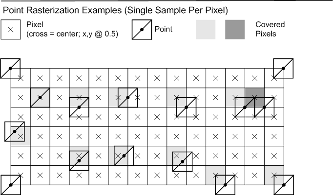
Any pixel sample locations which fall inside the triangle are drawn. An example with a single sample per pixel (at the center) is shown below. If a sample location falls exactly on the edge of the triangle, the Top-Left Rule applies, to ensure that adjacent triangles do not overdraw. The Top-Left rule is described below.
Top edge: If an edge is exactly horizontal, and it is above the other edges of the triangle in pixel space, then it is a "top" edge.
Left edge: If an edge is not exactly horizontal, and it is on the left side of the triangle in pixel space, then it is a "left" edge. A triangle can have one or two left edges.
Top-Left Rule: If a sample location falls exactly on the edge of a triangle, the sample is inside the triangle if the edge is a "top" edge or a "left" edge. If two edges from the same triangle touch the pixel center, then if both edges are "top" or "left" then the sample is inside the triangle.
Rasterization rules for infinitely-thin lines, with no antialiasing, are described below.
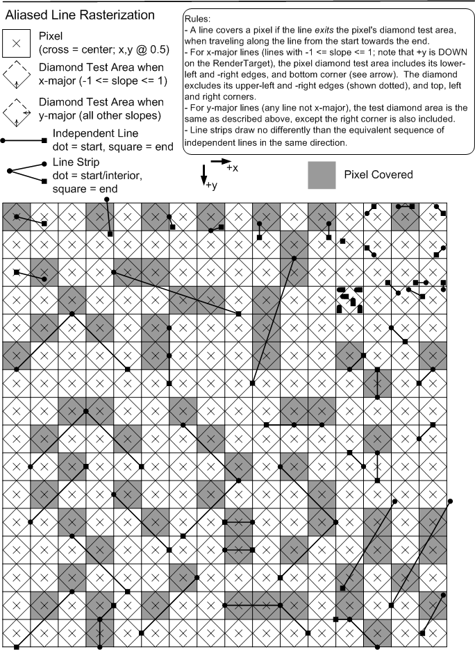
One futher implication of these line rasterization rules is that lines that are geometrically clipped to the viewport extent may set one less pixel than lines that are rendered to a larger 2D extent with the pixels outside the viewport discarded. (This is due to the handling of the line endpoints.)
Since geometric clip to the viewport is neither required nor disallowed, aliased line rendering is allowed to differ in viewport-edge pixels due to geometric clipping.
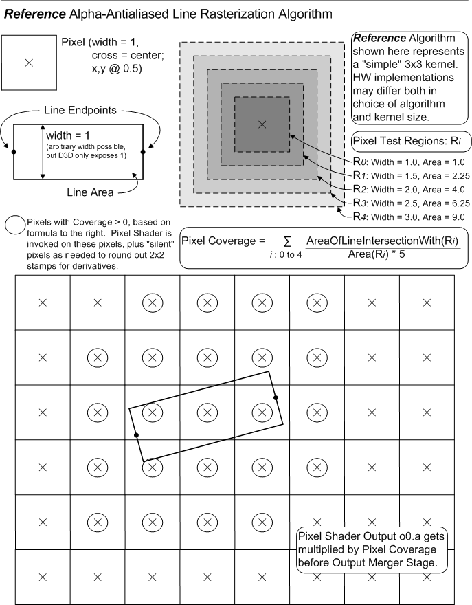
The alpha-based antialiased rasterization of a line (defined by two end vertices) is implemented as the visualization of a rectangle, with the line's two vertices centered on two opposite "ends" of the rectangle, and the other two edges separated by a width (in D3D11 width is only 1.0f). No accounting for connected line segments is done. The region of intersection of this rectangle with the RenderTarget is estimated by some algorithm, producing "Coverage" values [0.0f..1.0f] for each pixel in a region around the line. The Coverage values are multiplied into the Pixel Shader output o0.a value before the Output Merger Stage. Undefined results are produced if the PS does not output o0.a. D3D11 exposes no controls for this line mode.
It is deemed that there is no single "best" way to perform alpha-based antialiased line rendering. D3D11 adopts as a guideline the method shown in the diagram below. This method was derived empirically, exhibiting a number of visual properties deemed desirable. Hardware need not exactly match this algorithm; tests against this reference shall have "reasonable" tolerances, guided by some of the principles listed further below, permitting various hardware implementations and filter kernel sizes. None of this flexibility permitted in hardware implementation, however, can be communicated up through D3D11 to applications, beyond simply drawing lines and observing/measuring how they look.
The following is a listing of the "nice" properties that fall out of the above algorithm, which in general will be expected of hardware implementations (admittedly many of which are likely difficult to test):
Note that the wider the filter kernel an implementation uses, the blurrier the line, and thus the more sensitive the resulting perceived line intensity is to display gamma. The reference implmentation's kernel is quite large, at 3x3 pixel units about each pixel.
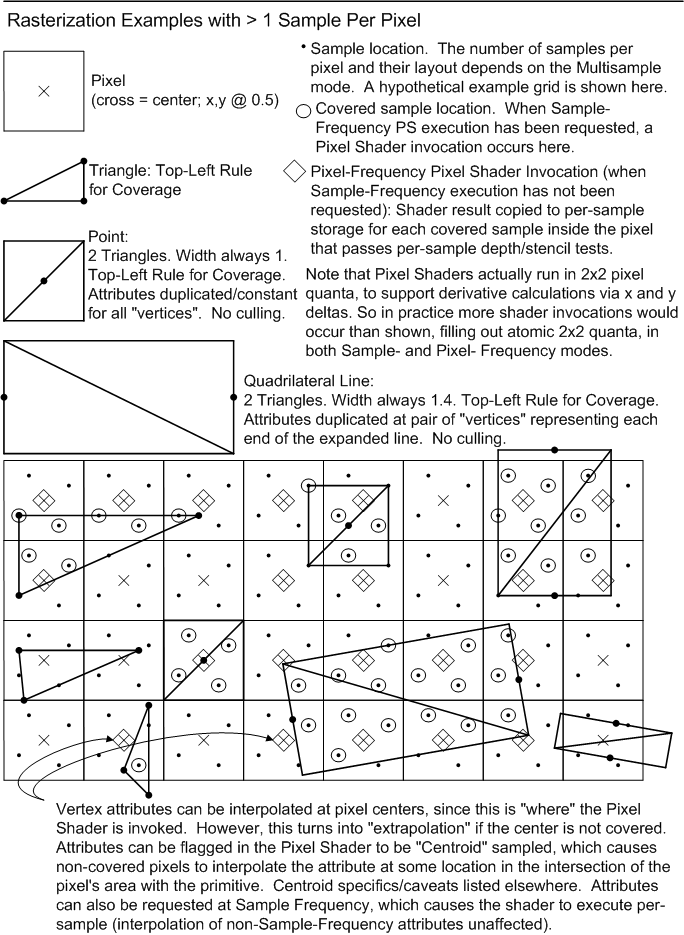
Quadrilateral lines take 2 endpoints and turn them into a simple rectangle with width 1.4f, drawn with triangles. The attributes at each end of the line are duplicated for the 2 vertices at each end of the rectangle.
This mode is not supported with center sample patterns (D3D11_CENTER_MULTISAMPLE_PATTERN) where there is more than one sample overlapping the center of the pixel, in which case results of drawing this style of line are undefined. See here(19.2.4.1).
For the purpose of rasterization, a point is represented as a square of width 1 oriented to the RenderTarget. Actual implementation may vary, but output behavior should be identical to what is described here. The coordinate for a point indentifies where the center of the square is located. Pixel coverage for points follows Triangle Rasterization Rules, interpreted as though a point is composed of 2 triangles in a Z pattern, with attributes duplicated at the 4 vertices. Cull modes do not apply to points.
Section Contents
(back to chapter)
3.5.1 Overview
3.5.2 Warning about the MultisampleEnable State
3.5.3 Multisample Sample Locations And Reconstruction
3.5.4 Effects of Sample Count > 1
Multisample Antialiasing seeks to fight geometry aliasing, without necessarily dealing with surface aliasing (leaving that as a shading problem, e.g. texture filterng). This is accomplished by performing pixel coverage tests and depth/stencil tests at multiple sample locations per pixel, backed by storage for each sample, while only performing pixel shading calculations once for covered pixels (broadcasting Pixel Shader output across covered samples). It is also possible to request Pixel Shader invocations to occur at sample-frequency rather than at pixel-frequency.
The MultisampleEnable Rasterizer State remains as an awkward leftover from D3D9. It no longer does what the name implies; it no longer has any bearing on multisampling; it only controls line rendering behavior now. The state should have been renamed/refactored, but the opportunity was missed in D3D11. For a detailed discussion about what this state actually does now, see State Interaction With Point/Line/Triangle Rasterization Behavior(15.14).
Specifics about sample locations and reconstruction functions for multisample antialiasing are dependent on the chosen Multisample mode, which is outside the scope of this section. See Multisample Format Support(19.2), and Specification of Sample Positions(19.2.4).
Rasterization behavior when sample count is greater than 1 is simply that primitive coverage tests are done for each sample location within a pixel. If one or more sample locations in a pixel are covered, the Pixel Shader is run once for the pixel in Pixel-Frequency mode, or in Sample-Frequency mode once for each covered sample that is also in the Rasterizer SampleMask. Pixel-frequency execution produces a single set of Pixel Shader output data that is replicated to all covered samples that pass their individual depth/stencil tests and blended to the RenderTarget per-sample. Sample-frequency execution produces a unique set of Pixel Shader output data per covered sample (and in SampleMask), each output getting blended 1:1 to the corresponding RenderTarget sample if its depth/stencil test passes.
Note that points(3.4.6) and quadrilateral lines(3.4.5) are functionally equivalent to drawing their area with triangles. So Sample-Frequency execution is easily defined for all of these primitives. For points, the samples covered by the point area (and in the RasterizerState's SampleMask) each get Pixel Shader invocations with attributes replicated from its single vertex (except one parameter is available that is varying - an ID identifying each sample from the total set of samples in the pixel). For quadrilateral lines, the two end vertices define how attributes interpolate along the length, staying constant across the perpendicular. Again, the samples covered by the area of the primitive (and in the SampleMask) each get a Pixel Shader invocations in Sample-Frequency execution mode, with unique input attributes per sample, including an ID identifying which sample it is.
Alpha-Antialiased Lines(3.4.4) and Aliased Lines(3.4.3) are algorithms that inherently do not deal with discrete sample locations within a pixel's area, and thus it is illegal/undefined to request Sample-Frequency execution for these primitives, unless the sample count is 1, which is identical to Pixel-Frequency execution.
Consider a Pixel Shader that operates only on pixel-frequency inputs (e.g. all attributes have one of the following interpolation modes(16.4): constant, linear, linear_centroid, linear_noperspective or linear_noperspective_centroid). Implementations need only execute the shader once per pixel and replicate the results to all samples in the pixel. Now suppose code is added to the shader that generates new outputs based on reading sample-frequency inputs. The existing pixel-frequency part of the shader behaves identically to before. Even though the shader will now execute at sample-frequency (so the new outputs can vary per-sample), each invocation produces the same result for the original outputs.
Though this example happens to separate out the different interpolation frequencies to highlight their invariance, of course it is perfectly valid in general for shader code to mix together inputs with any different interpolation modes.
When a sample-frequency interpolation mode(16.4) is not needed on an attribute, pixel-frequency interpolation-modes such as linear evaluate at the pixel center. However with sample count > 1 on the RenderTarget, attributes could be interpolated at the pixel center even though the center of the pixel may not be covered by the primitive, in which case interpolation becomes "extrapolation". This "extrapolation" can be undesirale in some cases, so short of going to sample-frequency interpolation, a compromise is the centroid interpolation mode.
Centroid behaves exactly as follows:
The term Conservative Rasterization has been used to describe basically a GPU rasterizer assist for shader computed antialiasing. This concept has not been actually implemented in GPUs, at least that are known, but the following short discussion of Conservative Rasterization somewhat motivates the alternative that is specified here - Target Independent Rasterization. Note that as of D3D11.3, hardware has evolved to support Conservative Rasterization(15.17).
Consider how multisampling works in D3D (or GPU rasterization in general). Each pixel has “sample” positions which cause Pixel Shaders to be invoked when primitives (e.g. triangles) cover the samples. For multisampling, a single Pixel Shader invocation occurs when at least one sample in a pixel is covered. Alternatively, D3D10.1+ also allows the shader to request that the Pixel Shader be invoked for each covered sample – this has historically been called “supersampling”.
The downside to these antialiasing approaches is they are based on a discrete number of samples. The more samples the better, but there are still holes in the pixel area between the sample points in which geometry rendered there does not contribute to the image.
Conservative Rasterization, instead, would ideally invoke the Pixel Shader if the area of a primitive (e.g. triangle) being rendered has any chance of intersecting with the pixel’s square area. It would then be up to shader code to compute whatever measure of pixel area intersection it desires. It may be acceptable for the rasterization to be “conservative” in that triangles/primitives are simply rasterized with a fattened screen space area that could include some pixels with no actual coverage – it doesn’t really matter since the shader will be computing the actual coverage.
The win is that the number of Pixel Shader invocations is reasonably bounded to the triangle extents (as opposed to rendering bounding rectangles), and the output can be “perfect” antialiasing if desired. This is particularly the case if also utilizing some other features in D3D11 that allow arbitrary length lists to be recorded per pixel.
However, the complexity of the shader code required to compute an analytic coverage solution with Conservative Rasterization might be too high for the benefit. An alternative scheme, Target Independent Rasterization is defined here, under the more mundane heading 'Forcing Rasterizer Sample Count' below. First though, some discussion about how Target Independent Rasterization can help in at least one scenario - path rendering in Direct2D.
A common usage scenario of Direct2D is to stroke and/or fill anti-aliased paths. The semantics of the Direct2D anti-aliasing scheme are different from MSAA. The key difference is when the resolve step occurs. With MSAA the resolve step typically happens once per frame. With Direct2D anti-aliasing the resolve step occurs after each path is rendered. To work around these semantic differences the Windows 7 version of Direct2D performs rasterization on the CPU. When a path is to be filled or stroked, an expensive CPU-based algorithm computes the percentage of each pixel that is covered by the path. The GPU is used to multiply the path color by the coverage and blend the results with the existing render target contents. This approach is heavily CPU-bound.
Target Independent Rasterization enables Direct2D to move the rasterization step from the CPU to the GPU while still preserving the Direct2D anti-aliasing semantics. Rendering of anti-aliased paths will be performed in 2 passes on the GPU. The first pass will write per-pixel coverage to an intermediate render target texture. Paths will be tessellated into non-overlapping triangles. The GPU will be programmed to use Target Independent Rasterization and additive blending during the first pass. The pixel shader used in the first pass will simply count the number of bits set in the coverage mask and output the result normalized to [0.0,1.0]. During the second pass the GPU will read from the intermediate texture and write to the application’s render target. This pass will multiply the path color by the coverage computed during the first pass.
In some cases, it will be faster for Direct2D to tessellate paths into potentially overlapping triangles. In these cases, the 1st pass will set the ForcedSampleCount to 16 and simply output the coverage mask to the intermediate (R16_UINT). The blender would be setup to do a bitwise OR, or XOR operation (depending on the scenario). The second pass would read this 16-bit value from the intermediate, count the number of bits set, and modulate the color being written to the render target.
There are 2 fallbacks that could be used to implement this algorithm on GPUs that do not support Target Independent Rasterization. The first fallback would render the scene N times, with alpha = 1/N and additive blending for the first step of the algorithm. This would produce the same results, but at the cost of resorting to multipass rendering to to mimic the effect of supersampling at the rasterizer. The second fallback would use MSAA to implement the first pass of the algorithm. Both fallbacks are bound by memory bandwidth (render target writes). Using Target Independent Rasterization would significantly reduce the memory bandwidth requirements of this algorithm.
Overriding the Rasterizer sample count means defining the multisample pattern at the Rasterizer independent of what RenderTargetViews(5.2) (or UnorderedAccessView(5.3.9)s) may be bound at the Output Merger (and their associated sample count / Quality Level).
The ForcedSampleCount state setting is located in the Rasterizer State(15.1) object.
    UINT ForcedSampleCount; // Valid values for Target Independent Rasterization (TIR): 0, 1, 4, 8, 16
                            // Valid values for UAV(5.3.9) only render: 0, 1, 4, 8, 16
                            // 0 means don't force sample count.
Devices must support all the standard sample patterns up to and including 16 for the ForcedSampleCount. This is even if the device does not support that many samples in RenderTarget / DepthStencil resources.
Investigations show that the 16 sample standard D3D pattern performs favorably with Direct2D's original software based rasterization pattern, which had the significant disadvantage of using a regular grid layout, even though it was 64 samples.
With a forced sample count/pattern selected at the rasterizer (ForcedSampleCount > 0), pixels are candidates for shader invocation based on the selected sample pattern, independent of the RTV ("output") sample count. The burden is then on shader code to make sense of the possible mismatch between rasterizer and output storage sample count, given the defined semantics.
Here are the behaviors with ForcedSampleCount > 0.
The above functionality is required for Feature Level 11_1 hardware.
D3D10.0 - D3D11.0 hardware (and Feature Level 10_0 - 11_0) supports ForcedSampleCount set to 1 (and any sample count for RTV) along with the described limitations (e.g. no depth/stencil).
For 10_0, 10_1, and 11_0 hardware, when ForcedSampleCount is set to 1, line rendering cannot be configured to 2-triangle (quadrilateral) based mode (i.e. the MultisampleEnable state cannot be set to true). This limitation isn't present for 11_1 hardware. Note the naming of the 'MultisampleEnable' state is misleading since it no longer has anything to do with enabling multisampling; instead it is now one of the controls along with AntialiasedLineEnable for selecting line rendering mode.
This limited form of Target Indepdendent Rasterization, ForcedSampleCount = 1, closely matches a mode that was present in D3D10.0 but due to API changes became unavailable for D3D10.1 and D3D11 (and Feature Levels 10_1 and 11_0). In D3D10.0 this mode was the center sampled rendering even on an MSAA surface that was available when MultisampleEnable was set to false (and this could be toggled by toggling MultisampleEnable). In D3D10.1+, MultisampleEnable no longer affects multisampling (despite the name) and only controls line rendering behavior. It turns out some software, such as Direct2D, depended on this mode to be able to render correctly on MSAA surfaces. As of D3D11.1, D2D can use ForcedSampleCount = 1 to bring back this mode consistently on all D3D10+ hardare and Feature Levels. D3D10.0 also supported depth testing in this mode as well, but it is not worth exposing that given it D2D did not expose it, and the full D3D11.1 definition of the feature doesn't work with depth/stencil.
D3D11 allows rasterization with only UAVs bound, and no RTVs/DSVs. Even though UAVs can have any/different sizes, essentially, the viewport/scissor identify the pixel dimensions. Before this feature, when rendering with only UAVs bound, the rasterizer was limited to a single sample only.
UAV(5.3.9)-only rendering with multisampling at the rasterizer is possible by keying off the ForcedSampleCount state described earlier, with the sample patterns limited to 0, 1, 4, 8 and 16. (The UAVs themselves are not multisampled in terms of allocation.) A setting of 0 is equivalent to the setting 1 - single sample rasterization.
Shaders can request pixel-frequency invocation with UAV-only rendering, but requesting sample-frequency invocation is invalid (produces undefined shading results).
The SampleMask Rasterizer State does not affect rasterization behavior at all here.
On D3D11.0 hardware, ForcedSampleCount can be 0, 1, 4 and 8 with UAV only Rasterization. D3D11.1 hardware additionally supports 16.
Attempting to render with unsupported ForcedSampleCount produces undefined rendering results - though if a ForcedSampleCount is chosen that could never be valid for TIR or UAV-only rendering the runtime will fail the Rasterizer State object creation immediately.
Pixel Shaders always run in minimum 2x2 quanta to be able to support derivative calculations, regardless of the RenderTarget sample count. These Pixel Shader derivative calculations, used in texture filtering operations, but also available directly in shaders, are calculated by taking deltas of data in adjacent pixels. This requires data in each pixel has been sampled with unit spacing horizontally or vertically.
RenderTarget sample counts > 1 do not affect derivative calculation methods. If derivatives are requested on an attribute that has been Centroid sampled, the hardware calculation is not adjusted, and therefore incorrect derivatives will often result. What the Shader expects to be a derivative wrt a unit distance in the x or y direction in RenderTarget space will actually be the rate of change with respect to some other direction vector, which also probably isn't unit length.
The point here is that it is the application's responsibility to exhibit caution when requesting derivative from Centroid sampled attributes, ideally never requesting them at all. Centroid sampling can be useful for situations where it is critical that a primitive's interpolated attributes are not "extrapolated", but this comes with some tradeoffs: First, centroid sampled attributes may appear to jump around as a primitive edge moves over a pixel, rather than changing continuously. Secondly, derivative calculations on the attributes become unreliable or difficult to use correctly (which also hurts texture sampling operations that derive LOD from derivatives).
Under sample-frequency execution, a 2x2 quad of Pixel Shaders executes for each sample index where that sample is covered in at least one of the pixels participating in the 2x2 quad. This allows derivatives to be calculated in the usual way since any given sample is located one unit apart horizonally or vertically from the corresponding sample in the neighboring pixels.
It is left to the application's shader author to decide how to adjust for the fact that derivatives calculated from spacings of one unit may need to be scaled in some way to reflect higher frequency shader execution, depending on the sample pattern/count.
Further important discussion of Pixel Shader derivatives is under Interaction of Varying Flow Control With Screen Derivatives(16.8).
Chapter Contents
(back to top)
4.1 Minimal Pipeline Configurations
4.2 Fixed Order of Pipeline Results
4.3 Shader Programs
4.4 The Element
Summary of Changes in this Chapter from D3D10 to D3D11.3
Back to all D3D10 to D3D11.3 changes.(25.2)
The rendering Pipeline encapsulates all state related to the rendering of a primitive. This includes a sequence of pipeline stages as well as various state objects.
Section Contents
(back to chapter)
4.1.1 Overview
4.1.2 No Buffers at Input Assembler
4.1.3 IA + VS (+optionally GS) + No PS + Writes to Depth/Stencil Enabled
4.1.4 IA + VS (+optionally GS) + PS (incl. Rasterizer, Output Merger)
4.1.5 IA + VS + SO
4.1.6 No RenderTarget(s) and/or Depth/Stencil and/or Stream Output
4.1.7 IA + VS + HS + Tessellation + DS + ...
4.1.8 Compute alone
4.1.9 Minimal Shaders
Not all Pipeline Stages must be active. This section clarifies this concept by illustrating some minimal configurations that can produce useful results. The Graphics pipeline is accessed by Draw* calls from the API. The alternative pipeline, Compute, is accessed by issuing Dispatch* calls from the API.
For the Graphics pipepine, the Input Assembler is always active, as it produces pipeline work items. In addition, the Vertex Shader is always active. Relying on the presence of the Vertex Shader at all times simplifies data flow permutations very significantly, versus allowing the Input Assembler with its limited programming flexibility to feed any pipeline stage.
Note that even though the Vertex Shader must always be active in the Graphics pipeline, in scenarios where applications really don't want to have a Vertex Shader, and must simply implement it as a trivial or nearly trivial sequence of mov's from inputs to outputs, the short length and simplicity of such "passthrough" shaders should not be a problem for hardware implementations to practically hide the cost of, one way or another.
A minimal use of the Input Assembler is to not have any input Buffers bound (vertex or index data). The Input Assembler can generate counters such as VertexID(8.16), InstanceID(8.18) and PrimitiveID(8.17), which can identicy vertices/primitives generated in the pipeline by Draw*(), or DrawIndexed*() (if at least an Index Buffer is bound). Thus Shaders can minimally drive all their processing based on the IDs if desired, including fetching appropriate data from Buffers or Textures.
If the shader stage before the rasterizer outputs position, and Depth/Stencil writes are enabled, the rasterizer will simply perform the fixed-function depth/stencil tests and updates to the Depth/Stencil buffer, even if there is no Pixel Shader active. No Pixel Shader means no updates to RenderTargets other than Depth/Stencil.
The Input Assembler + Vertex Shader (required) can drive the Pixel Shader directly (GS does not have to be used, but can be). If an application seeks to write data to RenderTarget(s), not including Depth/Stencil which were explained earlier, the Pixel Shader must be active. This implicitly Output Merger as well, though as described further below, there's no requirement that RenderTargets need to be bound just because rasterization is occuring.
The Input Assembler (+required VS) can feed Stream Output directly with no other stages active. Note that as described in the Stream Output Stage(14) section, Stream Output is tied to the Geometry Shader, however a "NULL" Geometry Shader can be specified, allowing the outputs of the Vertex Shader to be sent to Stream Output with no other stages active.
Whether or not the Pixel Shader is active, it is always legal to NOT have any output targets bound (and/or have output masks defined so that no output targets are written). Likewise for Stream Output. This might be interesting for performance tests which don't include output memory bandwidth (and which might examine feedback statistics such as shader invocation counts, which is itself a form of pipeline output anyway).
The Input Assembler (+required VS) can feed Stream Output directly with no other stages active. Note that as described in the Stream Output Stage(14) section, Stream Output is tied to the Geometry Shader, however a "NULL" Geometry Shader can be specified, allowing the outputs of the Vertex Shader to be sent to Stream Output with no other stages active.
Take any of the configurations above, and HS + Tessellator + DS can be inserted after the VS. The presence of the DS is what implises the presence of the Tessellator before it.
When the Compute Shader runs, it runs by itself. The state for both the Graphics pipeline shaders and Compute Shader can be simultaneously bound. The selection of which pipeline to use is Draw* invokes Graphics and Dispatch* invokes Compute.
All vertex shaders must have a minimum of one input and one output, which can be as little as one scalar value. Note that System Generated Values such as VertexID(8.16) and InstanceID(8.18) count as input.
The rendering Pipeline is designed to allow hardware to execute tasks at various stages in parallel. However observable rendering results must match results produced by serial processing of tasks. Whenever a task in the Pipeline could be performed either serially or in parallel, the results produced by the Pipeline must match serial operation. That is, the order that tasks enter the Pipeline is the order that tasks are observed to be propagated all the way through to completion. If a task moving through the Pipeline generates additional sub-tasks, those sub-tasks are completed as part of completing the spawning task, before any subsequent tasks are completed. Note that this does not prevent hardware from executing tasks out of order or in parallel if desirable, just as long as results are buffered appropriately such that externally visible results reflect serial execution.
One exception to this fixed ordering is with Tessellation. With the fixed function Tessellation stage, implementations are free to generate points and topology in any order as long as that order is consistent given the same input on the same device. Vertices can even be generated multiple times in the course of tessellating a patch, as long as the Tessellator output topology is not point (in which case only the unique points in the patch must be generated). This tessellator exception is discussed here(11.7.9).
Another exception to the fixed ordering of pipeline results is any access to an Unordered Transaction View of a Resource (for example via the Compute Shader or Pixel Shader). These types of Views explicitly allow unordered results, leaving the burden to applications to make careful choices of atomic instructions to access Unordered Transaction Views if deterministic and implementation invariant output is desired.
A Shader object encapsulates a Shader program for any type of Shader unit. All shaders have a common binary format and basically have the following typical layout. A helpful reference for this is the source code accompanying the Reference Rasterizer, which includes facilities for parsing the shader binary.
The Tessellation related shaders have a significantly different structure, particularly the Hull Shader, which appears as multiple phases of shaders concatenated together (not depicted here).
version
input declarations
output declarations
resource declarations
code

version
    describes the Shader type: Vertex Shader(vs),
    Hull Shader (hs), Domain Shader (ds),
    Geometry Shader (gs), Pixel Shader (ps),
    Compute Shader (cs).
    Example: vs_5_0, ps_5_0
input declarations
    declare which input registers are read
    Example:
        dcl_input v[0]
        dcl_input v[1].xy
        dcl_input v[2]
output declarations
    declare which output registers are written
    Example:
        dcl_output o[0].xyz
        dcl_output o[1]
        dcl_output o[2].xw
resource declarations
    Example:
        dcl_resource t0, Buffer, UNORM
        dcl_resource t2, Texture2DArray, FLOAT
code
    This Shader section contains executable instructions.
Section Contents
(back to chapter)
4.4.1 Overview
4.4.2 Elements in the Pipeline
4.4.3 Passing Elements Through Pipeline Interfaces
From the perspective of individual D3D11.3 Pipeline stages accessing and interpreting memory, all memory layouts (e.g. Buffer, Texture1D/2D/3D/Cube) are viewed as being composed of "Elements". An individual Element represents a vector of anywhere from 1 to 4 values. An Element could be an R8G8B8A8 packing of data, a single 8-bit integer value, 4 float32 values, etc. In particular, an Element is any one of the DXGI_FORMAT_* formats(19.1), e.g. DXGI_FORMAT_R8G8B8A8 (DXGI stands for "DirectX Graphics Infrastructure", a software component outside the scope of this specification which happens to own the list of DirectX formats going forward). Filtering may be involved in the process of fetching an Element from a texture, and this simply involves looking at multiple values for a given Element in memory and blending them in some fashion to produce an Element that is returned to the Shader.
Buffers in memory can be made up of structures of Elements (as opposed to being a collection of a single Element). For example a Buffer could represent an array of vertices, each vertex containing several elements, such as: position, normal and texture coordinates. See the Resources(5) section for full detail.
The concept of "Elements" does not only apply to resources. Elements also characterize data passing from one Pipeline stage to the next. For example the outputs of a Vertex Shader (Elements making up a vertex) are typically read into a subsequent Pipeline stage as input data, for instance into a Geometry Shader. In this scenario, the Vertex Shader writes values to output registers, each of which represents an individual Element. The subsequent Shader (Geometry Shader in this example) would see a set of input registers each initialized with an Element out of the set of input data.
There are various types of data interfaces in the hardware Pipeline through which Elements pass. This section describes the interfaces in generic terms, and characterizes how Elements of data pass through them. Specific descriptions for each of the actual interfaces in the Pipeline are provided throughout the spec, in a manner consistent with the principles outlined here. The overall theme here is that data mappings through all interfaces are always direct, without any linkage resolving required.
The first type of interface is Memory-to-Stage, where an Element from a Resource (Texture/Buffer) is being fetched into the some part of the Pipeline, possibly the "top" of the Pipeline (Input Assembler(8)), or the "side", meaning a fetch driven from within a Shader Stage. At the point of binding of memory Resources to these interfaces, a number is given to each Element that is bound, representing which input (v#) or texture (t#) "register" at the particular interface refers to the Element. Note that there is no linkage resolving done on behalf of the application; the Shader assumes which "registers" will refer to particular Elements in memory, and so when memory is bound to the interface, it must be bound (or declared, in cases where multiple Elements come from the same Resource in memory) at the "register" expected by the Shader.
For Memory-to-Stage interfaces, Elements always provide to the Shader 4 components of data, with defaults provided for Elements in memory containing fewer than 4 components (though this can be masked to be any subset of the 4 components in the Shader if desired).
For interfaces on the "side", where memory Resources are bound to Shader Stages so they can be fetched from via Shader code, the set of binding points (t# registers in the Shader) cannot be dynamically indexed within the Shader program without using flow control.
On the other hand, the interface at the "top" of the Pipeline (the input v# registers of the first active Shader Stage) can be dynamically indexed as an array from Shader code. The Elements in v# registers being indexed must have a declaration(22.3.30) specifying each range that is to be indexed, where each range specifies a contiguous set of Elements/v# registers, ranges do not overlap, and the components declared for each Element in a given range are identical across the range.
The second type of interface is Stage-to-Stage, where one Pipeline Stage outputs a set of 4 component Elements (written to output o# registers) to the subsequent active Pipeline Stage, which receives Elements in its input v# registers. The mapping of output registers in one Stage to input registers in the next Stage is always direct; so a value written to o3 always goes to v3 in the subsequent Stage. Any subset of the 4 components of any Element can be declared rather than the whole thing.
If more Elements or components within Elements are output than are expected/declared for input by the subsequent Stage, the extra data gets discarded / becomes undefined. If fewer Elements or components within Elements are output than are expected/declared for input by the subsequent Stage, the missing data is undefined.
Similar to the Memory-to-Stage interface at the "top" of the Pipeline, which feeds the input v# registers of the first active Pipeline Stage, at a Stage-to-Stage interface, writes to output Elements (o#) and at the subsequent Stage, reads from input elements (v#) can each be dynamically indexed as arrays from code at the respective Shaders. The Elements in o# registers being indexed must have a declaration(22.3.30) for each range, specifying a contiguous set of Elements/o# registers, without overlapping, and with the same component masks declared for each Element in a given range. The same applies to input v# registers at the subsequent stage (the array declarations for the input v# registers in the Shader are independent/orthogonal to the array declarations for o# in the previous Shader).
There is a detail which is mostly orthogonal to the the Stage-to-Stage interface discussion above: the frequency of operation at subsequent Stages varies, in addition to different amounts of data different Stages can input. For example the Geometry Shader(13) inputs all the vertices for a primitive. The Pixel Shader(16) can choose to have its inputs inperpolated from vertices, or take the data from one. The point of the above discussion is only to describe the mechanism for Element transport through the interfaces independently of these varying frequencies of operation between Stages.
The final type of interface is Stage-to-Memory, where a Pipeline Stage outputs a set of 4 component Elements (written to output o# registers) on a path out to memory. These interfaces (e.g. to RenderTargets or Stream Output) are somewhat the converse of the Memory-to-Stage Interface. Each memory Resource representing one or more Elements of output identifies each Element by a number #, corresponding directly to an output o# register. There is no linkage resolving done on behalf of the application; the application must associate target memory for Element output directly with each o# register that will provide it. Details on specifying these associations are unique for the different Stage-to-Memory interfaces (RenderTargets, Stream Output).
If a Stage-to-Memory interface outputs more Elements or components within Elements than there are destination memory bindings to accommodate, the extra data is discarded. If a Stage-to-Memory interface outputs fewer Elements or components within Elements than there are destination memory bindings expecting to be written, undefined data will be output (i.e. no defaults). At RenderTarget output, there are various means to mask what data gets output, most interesting of which is depth testing, but that is outside the scope of this discussion.
At the RenderTarget output interface (which is Pixel Shader(16) output), dynamic indexing of the o# registers is not supported. For the other Stage-to-Memory interface, Stream Output, indexing of outputs is permissible. Stream Output shares the output o# registers used for Stage-to-Stage output in the Geometry Shader(13) Stage, where indexing is permitted as defined for the Stage-to-Stage interface.
There are various hardware generated values which can each be made available when for input to certain Shader Stages by declaring them for input to a component of an input register. A listing of each System Generated Value in D3D11.3 can be found in the System Generated Value Reference(23), but in addition, here are links to descriptions of some (not all) of the System Generated Values: VertexID(8.16), InstanceID(8.18), PrimitiveID(8.17), IsFrontFace(15.12).
In the Hull Shader(10), Domain Shader(12) and Geometry Shader(13), PrimitiveID is a special case that has its own input register, but for all other cases of inputting hardware generated values into Shaders, (including the PrimitiveID into the Pixel Shader(16)), the Shader must declare a scalar component of one of its input v# registers as one of the System Generated Values to receive each input value. If that v# register also has some components provided by a the previous Stage or Input Assembler(8), the hardware generated value can only be placed in one of the components after the rest of the data. For example if the Input Assembler provides v0.xz, then VertexID might be declared for v0.w (since w is after z), but not v0.y. There cannot be overlap between the target for generated values and the target for values arriving from an upstream Stage or the Input Assembler.
Hardware generated values that are input into the generic v# registers can only be input into the first active Pipeline Stage in a given Pipeline configuration that understands the particular value; from that point on it is the responsibility of the Shader to manually pass the values down if desired through output o# registers. If multiple Stages in the pipeline request a hardware generated value, only the first stage receives it, and at the subsequent stages, the declaration is ignored (though a prudent Shader programmer would pass down the value manually to correspond with the naming).
Since VertexID(8.16), InstanceID(8.18) are both meaningful at a vertex level, and IDs generated by hardware can only be fed into the the first stage that understands them, these ID values can only be fed into the Vertex Shader. PrimitiveID(8.17) generated by hardware can only be fed into the Hull Shader, Domain Shader, as well as whichever of the follwing is the first remaining active stage: Geometry Shader or Pixel Shader.
It is not legal to declare a range of input registers as indexable(22.3.30) if any of the registers in the range contains a System Generated Value.
From the API point of view, System Generated Values and System Interpreted Values (below) may be exposed to developers as just once concept: "System Values" "SV_*".
In many cases, hardware must be informed of the meaning of some of the application-provided or computed data moving through the D3D11.3 Pipeline, so the hardware may perform a fixed function operation using the data. The most obvious example is "position", which is interpreted by the Rasterizer (just before the Pixel Shader). Data flowing through the D3D11.3 Pipeline must be identified as a System Interpreted Value at the output interface between Stages where the hardware is expected to make use of the data. For the case where the Input Assembler(8) is the only Stage present in a Pipeline configuration before the place where the hardware is expected to interpret some data, the Input Assembler(8) has a mechanism for identifying System Interpreted Values to the relevant (components of) Elements it declares.
A listing of each System Interpreted Value in D3D11.3 can be found in the System Interpreted Values Reference(24). Each System Interpreted Value has typically one place in the Pipeline where it is meaningful to the hardware. Also, there may be constraints on how many components in an Element need to be present (such as .xyzw for "position" going to the Rasterizer).
If data produced by the Input Assembler or by the output o# registers of any Stage is identified as a System Interpreted Value at a point in the pipeline where the hardware has no use for interpreting the data, the label is silently ignored (and the data simply flows to the next active Stage uninterpreted). For example if the Input Assembler labels the xyzw components of one of the Elements it is producing as "position", but the first active Pipeline Stage is the Vertex Shader, the hardware ignores the label, since there is nothing for hardware to do with a "position" going into the Vertex Shader.
Just because data is tagged as a System Interpreted Value, telling hardware what to do with it, does not mean the hardware necessarily "consumes" the data. Any data flowing through the Pipeline (System Interpreted Value or not) can typically be input into the next Pipeline Stage's Shader regardless of whether the hardware did something with the data in between. In other words, output data identified as a System Interpreted Value is available to the subsequent Shader Stage if it chooses to input the data, no differently from non-System Interpreted Values. If there are exceptions, they would be described in the System Interpreted Value Reference(24). One catch is that if a given Pipeline Stage, or the Input Assembler, identifies a System Interpreted Value (e.g. "clipDistance"), and the next Shader Stage declares it wants to input that value, it must not only declare as input the appropriate register # and component(s), but also identify the input as the same System Interpreted Value (e.g. "clipDistance"). Mismatching declarations results in undefined behavior. e.g. Identifying an output o3.x as "clipDistance", but not naming a declared input at the next stage v3.x as "clipDistance" is bad. Of course, in this example it would be legal for the subsequent Shader to not declare v3.x for input at all.
It is not legal to declare a range of input or output registers as indexable(22.3.30) if any of the registers in the range contains a System Interpreted Value, with the exception of System Interpeted Values for the Tessellator, which have their own indexing rules - see the Hull Shader(10) specification.
Note that there is no mechanism in the hardware to identify things that the hardware does not care about, such as "texture coordinate" or "color". At a high level in the software stack, full naming of all data may or may not be present to assist in authoring and/or discoverability, but these issues are outside the scope of anything that hardware or drivers need to know about.
Note that while it may seem redundant to label System Interpreted Values at both the place producing the values as well as the next stage inputting it (in the case where the next stage actually wants to input it), this helps hardware/drivers isolate the compilation step for Shader programs at different Stages from any dependency on each other, in the event the driver needs to rename registers to fit hardware optimally, in a way that is transparent to the application.
From the API point of view, System Generated Values and System Interpreted Values (above) may be exposed to developers as just once concept, "System Values" "SV_*".
In many cases in D3D11.3, an offset for an Element is required, a stride for a structure (e.g. vertex) is required, or an initial offset for a Buffer is required. All of these types of values have the following alignment restrictions:
Example byte alignments for some of the formats(19.1) which can be used in structures (e.g. vertex buffers) or as elements in index buffers:
However, these alignment rules do not apply to Buffer offsets when creating Views on Buffers. These Buffer offsets have more stringent requirements, detailed in the View section(5.2).
There is also some similar discussion, focused on memory accesses common to UAVs(5.3.9), SRVs and Thread Group Shared Memory in the Memory Addressing and Alignment Issues(7.13) section.
None of these rules are validated (except in debug mode) and violations will result in undefined behavior.
Chapter Contents
(back to top)
5.1 Memory Structure
5.2 Resource Views
5.3 Resource Types and Pipeline Bindings
5.4 Resource Creation
5.5 Resource Dimensions
5.6 Resource Manipulation
5.7 Resource Discard
5.8 Per-Resource Mipmap Clamping
5.9 Tiled Resources
Summary of Changes in this Chapter from D3D10 to D3D11.3
Back to all D3D10 to D3D11.3 changes.(25.2)
Several different Resource Types (arrangements of memory storage) are available for input or output by various Pipeline stages. The available Resource Types are: Buffer(5.3.4) (Typically a Structured(5.1.3) or "Unstructured(5.1.2) region of memory), Texture1D(5.3.5) (Homogeneous array of 1D Textures), Texture2D(5.3.6) (Homogeneous array of 2D Textures), Texture3D(5.3.7) (Volume Texture), and TextureCube(5.3.8) (3D enclosure). The Resource Type, in general, determines many characteristics, like whether the memory is Structured(5.1.3), where the Resource may be bound to in the graphics pipeline, how many mip levels there are, what the sampling behavior is, and other possible restrictions/properties on the Resource. Resources are built up of one or more Subresources, which each are a generalized 3D quantity of data which degenerates to store 2D and 1D quantities of data. The arrangement of Subresources to build up a Resource is tied to the Resource Type and dimensions.
There are also distinctions in how a Resource is bound to the graphics pipeline. The binding location can also be thought of as accepting either Buffers directly or accepting Views of Resources. Each binding location which accepts Views requires a unique View type for that location - e.g. Render Target View or Shader Resource View.
The size for mipmap slice subresources 1..n are computed sequentially from the size of the largest subresource (subresource 0, where for each mipped dimension:
mipslice N+1 size = floor( mipslice N size / 2)
The following diagram depicts Resources, their Subresource arrangement, and how they are sampled from within shaders. While the following diagram depicts deep mip mapping, it is valid to create Resources less than the maximum amount of mip levels.
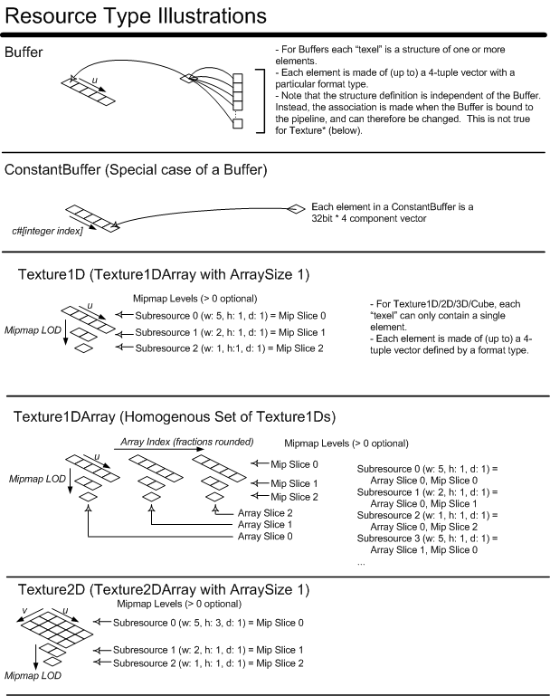
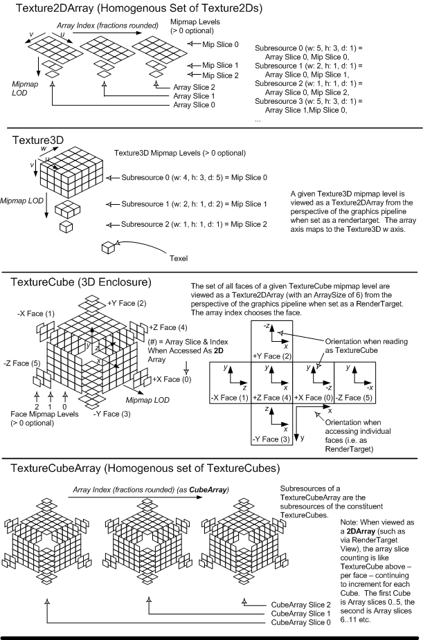
Section Contents
(back to chapter)
5.1.1 Overview
5.1.2 Unstructured Memory
5.1.3 Structured Buffers
5.1.4 Raw Buffers
5.1.5 Prestructured+Typeless Memory
5.1.6 Prestructured+Typed Memory
When a Resource is allocated, it's memory structure can generally be classified either as Unstructured, Prestructured+Typeless, or Prestructured+Typed.
Only the Buffer Resource(5.3.4) construction may be created as "Unstructured". Unstructured identifies the Resource as a single contiguous block of memory with no mipmaps, nor array slices. Unstructured Resources generally must have the memory structure defined when the Resource is bound to the graphics pipeline (providing types and offsets for the Element(s) in the Resource, as well as an overall stride). This memory structure can change freely, since it is late-bound to the Resource at the graphics pipeline binding location.
The same Unstructured Resource may be bound to multiple slots in the graphics Pipeline with different memory interpretations at each location, as long as the Resource is only being read from at each binding. The same Unstructured Resource may not be bound to read and write stages of the pipeline simultaneously for a single Draw/Dispatch operation.
Unstructured Resources do not have mipmaps nor array slices. See the Resource Binding Table(5.3.1) for descriptions of where Buffers (the only Resources that can be Unstructured) can be bound in the Pipeline.
Only the Buffer Resource(5.3.4) construction may be created as "Structured". Structured identifies the Resource as a single contiguous block of memory with no mipmaps, nor array slices, but it does have a structure size (stride), so that it represents an array of structures. Implementations can take advantage of knowing there is a fixed structure size in they way they lay out the memory physically (hidden from the application).
A number of application scenarios require the ability to write a structure of data out to an index in an array. E.g. Generating an unordered collection of output data in an Append buffer(5.3.10). Hardware may be optimized for smaller reads and writes than the stride of a data. Consider a group of 16 shader threads where each thread wants to write out the first 4 bytes of a structure. If the structure is only 4 bytes, the 16 threads will collectively write out 16 consecutive 32-bit locations, which tends to be fast. But if the structure is larger – say 64 bytes, then the 16 threads will each issue a write that is spaced 64 bytes apart. Then when reading the data back in a later pass, the same problem will be reoccur. Reads will be issued with a spacing equal to the stride of the structure, with larger structures likely to have more of a performance issue.
Due to the reads and the writes having similar access patterns it would be better to have the data layout in memory match the access pattern that occurs. Since the actual access pattern is hardware specific as well as the performance characteristics of reads spaced by stride boundaries, the design pattern of textures is followed to allow for better performance by hiding the physical layout of the memory.
The same Structured Resource may be bound to multiple slots in the graphics Pipeline, as long as the Resource is only being read from at each binding. The same Structured Resource may not be bound to read and write stages of the pipeline simultaneously for a single Draw/Dispatch operation.
Structured Resources do not have mipmaps nor array slices. See the Resource Binding Table(5.3.1) for descriptions of where Buffers (the only Resources that can be Structured) can be bound in the Pipeline.
Sometimes a convenient way to access the contents of a Buffer is to treat it simply as a huge bag of bits. The Raw view comes close to this, by allowing access to a Buffer in the form of 32-bit aligned addressing and accessing of data in chunks of 1-4 32-bit values, with no type.
Raw access to a Buffer is indicated when creating either a Shader Resource View(5.2) (SRV) or Unordered Access View(5.3.9) (UAV), with the flag D3D11_BUFFER_SRV_FLAG_RAW (SRV) or D3D11_BUFFER_UAV_FLAG_RAW (UAV).
To be able to create a RAW View, the underlying resource had to have been created with D3D11_RESOURCE_MISC_ALLOW_RAW_VIEWS.
This flag cannot be combined with D3D11_RESOURCE_MISC_STRUCTURED_BUFFER. Also, a Buffer created with D3D11_BIND_CONSTANT_BUFFER cannot also specify D3D11_RESOURCE_MISC_ALLOW_RAW_VIEWS. This is not a limitation, since Constant Buffers already have a constraint that they cannot be accessed with any other View in the first place.
Other than those invalid cases, specifying D3D11_RESOURCE_MISC_ALLOW_RAW_VIEWS when creating a Buffer does not limit any functionality versus not having it – e.g. the Buffer can be used for non-RAW access in any number of ways possible with D3D. Specifying the D3D11_RESOURCE_MISC_ALLOW_RAW_VIEWS flag only increases available functionality – it is just giving the system an early indication that the Buffer may participate in RAW style access in addition to other uses.
Any Resource type may be created as "Prestructured+Typeless". A structure size is provided, plus bit widths of components (but not the types of those components), and also dimensions (in units of structures) appropriate for the Resource type. This is unlike a Structured Buffer, which only specifies a structure size/stride and no definition of the contents of the structure. Before the Resource is bound to the pipeline, Resource Views must be created which will fully qualify the component's types. These Resource Views also allow the Resource to be decomposed into smaller compatible subgroupings of the Subresources. For example, a fully mipped DXGI_FORMAT_R32G32B32A32_TYPELESS Texture3D with a width of four, a height of three, and a depth of five, would have three mip levels. To use this texture, a Resource View would have to fully qualify the format of the Resource, possible to DXGI_FORMAT_R32G32B32A32_UINT. In addition, the Resource View could also regroup only the two least detailed mip levels or select only a particular mip level. This allows the original Resource to be manipulated as if it were a Resource made up of only a few Subresources within the original Resource. The full details of Resource Views(5.2) is described later.
The benefit of Prestructured+Typeless Resources is that memory may be used as weakly typed storage, enabling limited reuse or reinterpretation of the memory, as long as the component bit counts remain the same. The same Prestructured+Typeless Resource may be bound to multiple slots in the graphics pipeline with Views of different fully qualified formats at each location. This forces bit representations of formats to be well-defined with respect to each other.
For example, a Resource created with the format R32G32B32A32_TYPELESS may be used as R32G32B32A32_FLOAT and R32G32B32A32_UINT at different locations in the pipeline simultaneously.
Any Resource type may be created as "Prestructured+Typed", also known as creating the Resource with a fully-qualified type or format. In general, this may allow Resource optimizations, especially when the Resource is created with flags indicating that the Resource cannot be Mapped/ Locked by the application.
Special resource formats, such as Block Compression Formats(19.5), have the characteristic that in order to read an individual Element in the resource, there is not a unique location in the resource that corresponds to the Element. Some sort of decompression or decoding of data from locations in the resource that are not unique to a particular Element is required during the read process in order to resolve what an individual Element is (even when no filtering is being applied). Complex formats like this must be created as part of a "Prestructured+Typed" resource.
"Prestructured+Typed" and "Prestructured+Typeless" resources support mipmapping, as the combination of Resource type, dimensions and structure size provided during resource creation supply enough information to allocate all memory in the layout required. Additionally, Resource Views created against Prestructured+Typed Resources must have indentical Resource Formats as the Prestructured+Typed Resource.
Section Contents
(back to chapter)
5.2.1 Overview
5.2.2 Shader Resource View Support for Raw and Structured Buffers
5.2.3 Clearing Views
In order to indirectly bind a Resource to certain stages of the graphics pipeline, Resource Views must be used. In addition, since some Resources may be created as "Prestructured+Typeless", the View provides the final opportunity to fully qualify the Resource component's types. The Resource Views also allow the Resource to be decomposed into smaller compatible subgroupings of the Mip Slices, Array Slices, and Subresources. This means that the effective dimensions and array sizes of the Views will, naturally, always be less than or equal to the original Resource. Each stage of the pipeline requires a unique type of View, and each type of View may have it's own custom set of state parameters that are needed to complete the process of binding a particular Resource to the graphics pipeline stage. All necessary restrictions to the basic Resource have already been done through the Pipeline Bind Flags during Resource creation. These Resource Views are directly bound to the pipeline, instead of the Resource objects, themselves.
A resource view is distinct from the underlying resource from which the view was created, so where views are used, the view properties (number of mipmaps, number of array elements, type, etc.) are always used in place of the properties of the original resource. Thus, for example, a render target array index of zero always indicates the first array element in the view, even if the first array element in the view is not the first array element in the underlying resource. Out of range behaviors are also always with respect to the view properties where views are used.
Each unique View type has certain restrictions associated with the bind location of the graphics pipeline stage. For example, Render Target Views of Buffers may have a maximum width of 16384. This maximum is smaller than the maximum size of a Buffer (min(max(128,0.25f * (Amount of Dedicated VRAM)),2048) MB), so only a subsection of large Buffers may be bound as a Render Target at a time. In addition, Render Target Views of Texture3D may have a maximum array size of 2048. This fortunately matches the maximum W dimension size of a Texture3D (2048).
When Views are created of Buffers, restrictions are placed on the View's starting offset in the Buffer. If represented as a byte offset, the offset must be a multiple of the View Element Size. Another way to comply with this restriction is by specifying the Buffer offset in an integral number of View Elements. In addition, there exists another restriction on Buffer View creation. Views of the R32G32B32 element type cannot be created on a Buffer which had the Pipeline Bind flag of IAVERTEXINPUT, IAINDEXINPUT, CONSTANTBUFFER, or STREAMOUTPUT set. This prevents an R32G32B32 element from being used simultaneously as vertex and texture data.
To characterize the kind of decomposition that Shader Resource Views are capable of, here's a complete listing of the number of Views that are possible with a Texture2D Resource that was created fully mipped with the most detailed LOD: width = 4, height = 4, arraysize = 3.
The Views bound at the Render Target, Depth Stencil and Unordered Access binding locations in the pipeline have futher restrictions, in that they can only choose a Mip Slice, aka. select only one mip level. Here's a listing of the possible decomposition that can occur with Render Target, Depth Stencil and Unordered Access Views of the same Resource used in the previous example:
The following DDIs indicate the way Shader Resource Views (SRVs) are created, allowing read-only access to Raw and Structured Buffers in any shader stage.
Making an SRV of a Raw buffer allows it to be declared for read in any shader stage by the ld_raw instruction. This is accomplished by specifying a flag on creation of the Buffer View requesting Raw access (D3D11_DDI_BUFFEREX_SRV_FLAG_RAW) shown below.
In contrast, if the underlying Buffer was created as a Structured Buffer, then any SRV of the Buffer inherits the Structured semantics. In this case all shader stages can declare the resource for read by the ld_structured instruction. Note that unlike _RAW views (where the View decides that the Buffer will be "viewed" as RAW), nothing about the creation of a View of a Structured Buffer needs to indicate that it is structured, because once the Structured property is assigned to a Buffer on creation of the resource (including a structure stride), all Views on the Buffer are automatically Structured.
typedef struct D3D11DDIARG_BUFFER_SHADERRESOURCEVIEW
{
    UINT     FirstElement;
    UINT     NumElements;
} D3D11DDIARG_BUFFER_SHADERRESOURCEVIEW;


// BufferEx - Ex means extra pararameters
typedef struct D3D11DDIARG_BUFFEREX_SHADERRESOURCEVIEW
{
    UINT     FirstElement;
    UINT     NumElements;
    UINT     Flags; // See D3D11_DDI_BUFFEREX_SRV_FLAG* below
} D3D11DDIARG_BUFFER_SHADERRESOURCEVIEW;
#define D3D11_DDI_BUFFEREX_SRV_FLAG_RAW         0x00000001

typedef struct D3D11DDIARG_CREATESHADERRESOURCEVIEW
{
    D3D11DDI_HRESOURCE    hDrvResource;
    DXGI_FORMAT           Format;
    D3D11DDIRESOURCE_TYPE ResourceDimension;

    union
    {
        D3D11DDIARG_BUFFER_SHADERRESOURCEVIEW    Buffer;
        D3D11DDIARG_TEX1D_SHADERRESOURCEVIEW     Tex1D;
        D3D11DDIARG_TEX2D_SHADERRESOURCEVIEW     Tex2D;
        D3D11DDIARG_TEX3D_SHADERRESOURCEVIEW     Tex3D;
        D3D11DDIARG_TEXCUBE_SHADERRESOURCEVIEW   TexCube;
        D3D11DDIARG_BUFFEREX_SHADERRESOURCEVIEW  BufferEx;
    };
} D3D11DDIARG_CREATESHADERRESOURCEVIEW;
Clearing is an optimized operation to enable filling Render Target, Depth Stencil and Unordered Access Views with certain clear values.
The floating point values passed in through the DDI must be converted to the fully qualified format type of the View desired to be cleared. The standard type conversion rules(3.2) indicate how to convert to most values; but these conversion rules do not explicitly handle the case where the destination fixed point format contains more integer bits than the floating point format mantissa. When converting these floating point values to a format such as DXGI_FORMAT_R32G32B32A32_UINT or _SINT, the closest value is chosen. When the original floating point absolute value is larger than 2^24, the least significant bits of the destination are to be filled with 0's for _UINT and positive _SINT; or 1's for negative _SINT values.
The full extent of the resource view is always cleared. Viewport and scissor are not applied.
Depth clear values outside of the range specified in viewport range(15.6.1) will not be passed to the DDI.
    // part of user mode Device interface:
    STDMETHOD_( void, ClearRenderTarget )(
        D3D10DDI_HDEVICE hDevice,
        D3D11DDI_HRENDERTARGETVIEW hRenderTargetView,
        FLOAT ColorRGBA[ 4 ] );
    STDMETHOD_( void, ClearDepthStencil )(
        D3D10DDI_HDEVICE hDevice,
        D3D11DDI_HDEPTHSTENCILVIEW hDepthStencilView,
        UINT DSFlags, FLOAT Depth, UINT8 Stencil );
For UnorderedAccessViews(5.3.9), there are a couple of ways to Clear the View.
ClearUnorderedAccessViewUint(...) clears a UAV with bit-precise values, copying the lower ni bits from each array element i to the corresponding channel, where ni is the number of bits in the ith channel of the resource Format (for example, R8G8B8_FLOAT has 8 bits for the first 3 channels). This works on any UAV with no format conversion. For RAW Buffer and Structured Buffer Views, only the first array element’s value is used.
ClearUnorderedAccessViewFloat(...) clears a UAV with a float value. It only works on FLOAT, UNORM, and SNORM UAVs, with format conversion from FLOAT to *NORM where appropriate. On other UAVs, the operation is invalid and the call will not reach the driver.
    // part of user mode Device interface:
    STDMETHOD_( void, ClearUnorderedAccessViewUint)(
        D3D10DDI_HDEVICE hDevice,
        D3D11DDI_HRENDERTARGETVIEW hRenderTargetView,
        UINT Values[ 4 ] );
    STDMETHOD_( void, ClearUnorderedAccessViewFloat)(
        D3D10DDI_HDEVICE hDevice,
        D3D11DDI_HDEPTHSTENCILVIEW hDepthStencilView,
        FLOAT Values[ 4 ] );
View clearing command, implemented however the driver sees is the most efficient way. The primary distinction here versus the other Clears described above in D3D11 is that this takes a list of rects (an empty list clears the entire surface). This method only works on RTV, UAV, or any Video View of a Texture2D surface (runtime drops invalid calls). All array slices in the view get the same clear applied (any rects apply to each array slice).
The driver or hardware is responsible for clamping rects to the surface extents.
Color values are converted/clamped to the destination format as appropriate per D3D conversion rules. E.g. if the format of the view is R8G8B8A8_UNORM, inputs are clamped to 0.0f to 1.0f (NaN to 0).
If the format is integer, such as R8G8B8A8_UINT, inputs are taken as integral floats, so 235.0f maps to 235 (fractions rounded to zero, out of range/INF values clamped to target range, NaN to 0).
typedef VOID ( APIENTRY* PFND3D11_1DDI_CLEARVIEW )(
    D3D10DDI_HDEVICE hDevice,
    D3D11DDI_HANDLETYPE viewType, // View type that supports this clear
                                  // (RTV, UAV or any Video view).
                                  // Must be a Texture2D{Array} resource only
    VOID* hView,
    const FLOAT[4] color, // interpretation of color is view / format specific
    const D3D10_DDI_RECT* pRect, // Rect is subject to aligment constraints based on format being cleared.
                                // e.g. Subsampled video formats require rect extents snapped to full sample boundary
                                // NULL means clear the entire view.
    UINT numRects
     );
Color Mappings for RTVs and UAVs:
Color[0]: R
Color[1]: G
Color[2]: B
Color[3]: A
(e.g. An RTV of the Y plane of an NV12 surface, of format R8_*, would take the color from R.  An RTV of the UV plane of an NV12 surface, of format R8G8_*, would take the color from RG.)

Color Mappings for Video Views:
Color[0]: Y
Color[1]: U/Cb
Color[2]: V/Cr
Color[3]: A
For Video Views with YUV or YCbBr formats, no color space conversion happens – and in cases where the format name doesn’t indicate _UNORM vs. _UINT etc., _UINT is assumed (so input 235.0f maps to 235 as described above).
This feature is required to be supported for all D3D10+ hardware in D3D11.1 drivers and for D3D9 drivers maps to the already existing functionality there. The D3D9 equivalent honored the scissor rect, so emulation of ClearView on the D3D9 DDI will unset scissor / clear / reset scissor to achieve the intended behavior of ClearView (e.g. this scissor manipulation isn't needed on the new D3D11.1 ClearView DDI which ignores scissor/viewports by definition.).
Having this Clear with rects provides parity with D3D9 where there was a similar Clear that in particular was used for video. With Video added to D3D11 (outside the scope of this spec), adding this ClearView provides parity with D3D9.
Direct2D will be another user of this for rendering scenarios that map to a fill.
For RTVs and UAVS: The space the ClearView rects apply on is that of the view format (as opposed to the surface format, which for video surfaces can be different sizes). This is consistent with how Viewports and rendering work on those views. e.g. for a 64x64 YUYV surface, an RTV with the format R8G8B8A8_UINT appears in shaders (and to RSSetViewports()) as having dimensions 32x64 RGBA values. ClearView’s rects apply to the same space. The “color” coming into ClearView is just maps to the channels in the view (RGBA) ignoring the video layout. So a single clear color could really mean “stripes” of color if interpreted in video space. That’s not interesting to do, but it just falls out and isn’t worth bothering to validate out – the user who makes D3D views of video surfaces has to know they are operating on the raw memory via D3D – be it shaders or APIs like ClearView.
By contrast, ClearView on Video Views (the views that are used with the video pipeline and not D3D Rasterization) operate on logical surface dimensions. So a 64x64 YUYV surface appears as though it is that size, and so rects passed into ClearView are in that full 64x64 space (not 32x64). It is undefined to request clearing non-aligned rects (covering only half of the pixel pairs). The color passed into ClearView is just a single YUV value that is appropriately replicated for subsampled pixels by the driver. Video Views hide the memory layout from the API user, so they do not have to worry about what type of subsampling is going on (an exception is the alignment of the rect bounds).
Section Contents
(back to chapter)
5.3.1 Overview
5.3.2 Performant Readback
5.3.3 Conversion Resource Copies/ Blts
5.3.4 Buffer
All Resources must be qualified with a set of Pipeline Bind flags at creation time to indicate where in the graphics pipeline the Resource may be bound. Binding a Resource at a certain pipeline location imposes certain restrictions on the Resource for it's entire lifetime. Naturally, Resources may be bound at more than one location in the pipeline (even simultaneously within certain restrictions), but the Resource must satisfy all the restrictions that each Pipeline Bind flag imposes. Certain pipeline locations only accept Resource Views(5.2) to be bound to them. In such a case, the presence of the Pipeline Bind flag indicates that Resource Views can be created against the Resource in order to bind the Resource to such a pipeline location. Sometimes Pipeline Bind flags impose restrictions which conflict with each other, so such Pipeline Usage flags are naturally mutually exclusive. Otherwise, explicit mention is given when one Pipeline Bind flag prevents the usage of other Pipeline Bind flags.
The following table indicates which Resource Types may be bound to which available graphics Pipeline locations. A single entire Resource may not be able to have itself bound entirely to both an input and output Pipeline stage during a Draw operation. However, it is possible to refer to discrete components of the Resource, with Resource Views(5.2), allowing the same Resource to be bound as an input and output simultaneously, as long as the different Views do not share the same Subresources. For example: A two-dimensional mipped Resource created with the appropriate Pipeline Bind flags may have Subresources bound as Shader Resource Inputs, and a mutually exclusive Subresource from the same Resource bound as a RenderTarget Output, by using different Views.
| Resource Type | Input Assembler Vertex or Index | Shader Resource Input | Shader Constant Input | Stream Output | RenderTarget Output | Depth/ Stencil Output |
|---|---|---|---|---|---|---|
| Buffer | U | V | U | U | V | |
| Texture1D | V | V | V | |||
| Texture2D | V | V | V | |||
| Texture3D | V | V | ||||
| TextureCube | V | V | V |
Any Resource that is used as an output for the graphics pipeline cannot be mapped/ locked. This is not meant to block an application from viewing the contents of such a Resource. It is expected that to read the contents of such Resources in a performant manner, the contents must be copied to a Resource which is able to be mapped/ locked for CPU read access. Typically, the Resource which is able to be mapped/ locked will not be marked with any Pipeline Bind flags, and as such is expected to be a driver allocated system memory Resource which is allocated in such a fashion to be compatible with the hardware DMA engine. The Resource is also expected to be allocated for performant CPU reads. This enables an asynchronous performant read back for the CPU.
The Performant Readback(5.3.2) scenario highlights the need that for any device-dependent memory arrangement, used to optimize GPU Resources which cannot be mapped/ locked, there is always a performant ability to convert the memory arrangement into the device-independent memory arrangement that will be used to satisfy the map/ lock. This principle also relates to input Resources that cannot be mapped/ locked. Since non-mappable/ non-lockable input Resources may use a device-dependent memory arrangement and still be updated with UpdateSubresourceUP(5.6.8), CopyResource(5.6.3), and CopySubresourceRegion(5.6.2). Therefore, there is a need for a performant ability to convert the device-indepenedent memory arrangement into any device-dependent memory arrangement.
The Buffer is the only Resource which can be created as Unstructured(5.1.2). When the Buffer is bound to the graphics Pipeline, it's memory interpretation generally must also be bound to the graphics Pipeline along with it (providing types and offsets for the Element(s) in the Resource, as well as an overall stride). Sometimes this information is bound or described separately.
A Buffer has neither multiple mip levels nor multiple array slices, so a Buffer is made up of only a single Subresource. Buffers can be bound at multiple places in the pipeline simulatenously during a Draw call as long the Buffer is only read from at each location. If the Buffer is being written to, then the Buffer may only be bound to one location in the pipeline during a Draw call.
When a Buffer has been created with the Pipeline Bind flag indicating that it may be used as an Input Assembler Vertex Input, the Buffer may be contain multiple types of data per vertex. This data type, offset, and stride binding is done when the Resource is bound to the Pipeline.
When a Buffer has been created with the Pipeline Bind flag indicating that it may be used as an Input Assembler Index Input, and the Buffer is bound as an Index Input, at the time of binding, the format must be specified as one of: R16_UINT, or R32_UINT.
When a Buffer has been created with the Pipeline Bind flag indicating that it may be used as a Shader Constant Input, the format of the Buffer is assumed to be R32G32B32A32_TYPELESS when bound as a Shader Constant Input. The Buffer size viewable from a shader is restricted to hold a maximum of 4096 elements. The overall buffer size can be larger - see Offsetting Constant Buffer Bindings(5.3.4.3.2). The usage of Constant Buffers within the shaders is expected to make Shader execution more efficient than using ld(22.4.6) or sample(22.4.15) with a Shader Resource within the Shader. Constant Input is read into a Shader given an integer array index to fetch a single Element. This is similar to point sampling of a texture; as there is no filtering. Constant Input is only needed to store Shader constants which could change between Draw() calls, as opposed to Immediate Constants or an Immediate Constant Buffer, which is are embedded into a Shader.
A Shader Constant Resource is expected to be optimized for moving constant data from the CPU to the graphics adapter, and as such, may not be able to be mapped/ locked, allowing the CPU to read the contents of the Buffer directly. Therefore, the Resource may only be CPUWRITE (write-only) or not mappable/ lockable. In addition, if the Resource is mappable/ lockable, Map/ Lock must be called with DISCARDRESOURCE. NOOVERWRITE is not valid on Shader Constant Resources either. The Resource may still be used with CopyResource(5.6.3) and CopySubresourceRegion(5.6.2). All other Pipeline Bind flags are prevented from being used, disallowing constant buffers to be vertex buffers, streamed out to or rendered to, etc.
Map() allows NO_OVERWRITE for Constant Buffers. This was disallowed before D3D11.1.
Similarly, UpdateSubresource1() adds the ability to perform partial Constant Buffer updates. So the pDstBox parameter does not have to be null NULL when updating Constant Buffers via UpdateSubresource1(). Either NO_OVERWRITE or DISCARD flags must be specified for a partial update, and the extents of the pDstBox parameter must be aligned to 16 byte (full constant) boundaries or the call is dropped.
Before the first call with NO_OVERWRITE on a deferred context, a DISCARD must be done on the same context (via Copy*()/Update*()/Map() API flag or Discard*() API). This is not required on immediate contexts if the application knows the GPU is finished with the resource (though discard can be used if not).
This feature is required to be supported for all D3D10+ hardware with D3D11.1 drivers.
This allows applications to partially go back to a DX9 style convention where they have the ability to set invidivual constants in a Constant Buffer if they like (albeit with the new simplifying NO_OVERWRITE limitation - the updates can't conflict with existing constant references that may be in flight on the GPU). The restriction to not allow partial Constant Buffer updates when Constant Buffers were added to D3D10 was intended to simplify the system handling of shader constants on the assumption that applications could simply organize their constant data in to groups, each with its own Constant Buffer, organized by frequency of update. The impression seems to be that in many cases this restriction was a net performance loss for applications, hence this proposed change to at least partially loosen up Constant Buffer updates.
A common desire for high performance game engines is to collect a large batch of Constant Buffer updates for constants to be referenced by separate Draw*() calls, each needing their own constants, all at once. This is facilitated by allowing the application to create a large Buffer and then pointing individual shaders to regions within it (kind of like a View, but without having to make a whole object to describe the view).
Constant Buffers are allowed to be created larger than the maximum Constant Buffer size that an individual shader can reference, which is at most 4096 16-byte elements - 65kB. Each "element" is one 4-component Shader Constant.
The Constant Buffer Resource size is limited only by the size of memory allocation the system is capable of handling (limits defined elsewhere, and more than large enough for the purpose of the discussion here).
When a Constant Buffer larger than 4096 elements in size is bound to the pipeline via *SetShaderConstants() APIs [e.g. VSSetShaderConstants()], it appears to the shader as if it is only 4096 elements in size.
Variants of the *SetShaderConstants() APIs, *SetShaderConstants1() allow a "FirstConstant" and "NumConstants" to be specified along with the binding. When the shader accesses a Constant Buffer bound this way it will appear as if it starts at the specified "FirstConstant" offset (where 1 means 16 bytes) and has a size defined by NumConstants (number of 16 byte Constants). This is basically a lightweight "View" of a region of a larger Constant Buffer.
FirstConstant must be a multiple of 16 constants.
NumConstants must be a multiple of 16 constants, in the range [0..4096].
If any part of the range defined by FirstConstant and ConstantCount falls off the underlying resource, accesses to those addresses count as out of bounds reads from the shader, which is defined to return 0 for all components.
This feature is required to be supported for all D3D10+ hardware in D3D11.1 drivers and is emulated by the runtime on Feature Level 9_x running on D3D9 drivers.
When a Buffer has been created with the Pipeline Bind flag indicating that it may be used as a Shader Resource Input and it is a typed Buffer (the view specifies a format type), it may be read from within shaders with the load(22.4.6). See the description of this instruction for detail. To use a typed Buffer as a Shader Resource Input, it must be bound at one of the available 128 slots for input Resources, by first creating the appropriate View for this particular stage of the graphics pipeline. It is fine for the same Buffer to be bound to multiple slots simultaneously, possibly even with different Element formats or inital offsets. However at each binding, only a single Element type is permitted, and the data stride is implied to be equal the Element size. In other words, "Array-of-structure" style layouts cannot be described for typed Buffers bound at Shader Resource Input. Structured Buffers allow array-of-structures access, though without any automatic format conversion for elements.
Just like Typed Buffers, Raw and Structured Buffers can be bound to the pipeline via Shader Resource Views for reading into shaders via ld_raw(22.4.10) and ld_structured(22.4.12) instructions, respectively.
Details of the usage of such a Resource are described in the Streaming Output section(14). There are two types of bindings available for Stream Output Buffers, one that treats a single output Buffer as a Multiple-Element Buffer (array-of-structures), while the other permits multiple output Buffers each treated as Single-Element Buffers (structure-of-arrays). Single-Element Buffer output is expected to be used typically for recirculation (subsequently) as a Shader Resource Input, but this can also be used as Input Assembler Vertex Input. Multiple-Element Buffer output is only intended to be used for recirculating data (subsequently) back as Input Assembler Vertex Input (since Multiple-Element Buffer access is not currently available in Shaders).
If the Resource has the Input Assembler Vertex Input Pipeline Bind flag specified, the Resource may also be used with DrawAuto(8.9).
Since this is an output stage, Resources with this Pipeline Bind flag are not able to be mapped/ locked for CPU access ever. This doesn't prevent Resources completely from being viewed by the CPU, as there are performant(5.3.2) methods for viewing the contents of the Resource.
When a Buffer has been created with the Pipeline Bind flag indicating that it may be used as a RenderTarget Output, this Pipeline Bind flag indicates that Render Target Views may be created with this Resource.
Constraints when a Buffer is used as RenderTarget output: it cannot be paired with any Depth/Stencil Output (i.e. no depth buffering); it can only have a single Element defined, with a data stride implied to be equal to the Element width; the View is limited to a maximum width of 16384 (multiple Views with different offsets would be needed to leverage the entire Buffer). In all other regards, a Buffer render target output is identical to the Texture1D case.
Since this is an output stage, Resources with this Pipeline Bind flag are not able to be mapped/ locked for CPU access ever. This doesn't prevent Resources completely from being viewed by the CPU, as there are performant(5.3.2) methods for viewing the contents of the Resource.
When the Unordered Access Pipeline Bind has been indicated, Unordered Access Views may be created for use at the Compute Shader or Pixel Shader.
A Texture1D is a homogeneous array of 1D Textures. The array is homogeneous in the sense that each Texture has the same data format and dimensions (including miplevels). The entire array of Textures are created atomically. The memory for the entire Resource need not be contiguous. A Texture1D may not be created as Unstructured(5.1.2), but may be created as Prestructured+Typeless Memory(5.1.5) or as Prestructured+Typed Memory(5.1.6). As illustrated by the diagram(5) and binding configurations(5.3.1), a Texture1D may be decomposed into sub-groups of Mip Slices, Array Slices, and Subresources in order to refer to discrete components of the Resource to accomplish certain operations. The decomposition for graphics Pipeline Binding is achieved through the usage of Views for each stage of the pipeline.
Like other Resources, a Texture1D must be qualified with a set of flags at creation indicating where in the graphics pipeline the Resource may be bound. Naturally, the Resource may be bound at more than one location in the pipeline, but the Resource must've been created with the restrictions that each Pipeline Usage flag indicates. Sometimes Pipeline Bind flags have restrictions which conflict with each other, so such Pipeline Bind flags are mutually exclusive.
When the Texture1D has been created with the Pipeline Bind flag indicating that it may be used as a Shader Resource Input, the Texture1D Resource may be read from within shaders with the ld(22.4.6) or sample(22.4.15) instructions, after they are bound to the pipeline through the usage of Views. See the descriptions of these instructions for details. Each Element from a Texture1D to be read into a Shader counts towards a limit on the total number of elements addressable from Resources (128). Texture1D Resources are addressed from the Shader with a 1D coordinate plus a 2nd coordinate specifying which Array Slice in the Texture1D to fetch from. The 2nd coordinate, if provided as floating point data, is rounded (nearest even), producing an integral array index. Typical 1D filtering occurs on the Array Slice chosen by the 2nd coordinate.
When a Texture1D Mip Slice is bound as a RenderTarget Output, through the usage of Views, it is allowable to use either an accompanying Texture1D Depth/ Stencil of the same dimensions. For example, if the most detailed Mip Slice View of a Texture1D (width=6, arraysize=8) is bound as a RenderTarget Output; an effective Texture1D View of (width=6, arraysize=8) may be used as a Depth/ Stencil. Also, the particular Array Slice in the Texture1D to render is chosen, from the Geometry Shader stage, by declaring a scalar component output data as the System Interpreted Value "renderTargetArrayIndex". If such a value is not present in primitive data reaching the rasterizer, the default is to render to Array Slice 0.
Rasterization to Texture1D resources is identical to rasterizing to a Texture2D resource with a y dimension of 1, thus both x and y coordinates are honored and only rendering that covers the Nx1 area of these resources will update them.
Since this is an output stage, Resources with this Pipeline Bind flag are not able to be mapped/ locked for CPU access ever. This doesn't prevent Resources completely from being viewed by the CPU, as there are performant(5.3.2) methods for viewing the contents of the Resource.
When the Texture1D has been created with the Pipeline Bind flag indicating that it may be used as a Depth/ Stencil Output, the Texture1D Resource may only be one of a few Resource Formats (essentially only those which have a 'D' component or those TYPELESS formats which can be converted to a format with a 'D' component), such as D32_FLOAT or R32_TYPELESS, etc.
Resources created with this Pipeline Bind flag cannot also be used as a RenderTarget (the two flags are mutually exclusive).
Since this is an output stage, Resources with this Pipeline Bind flag are not able to be mapped/ locked for CPU access ever. In addition, Depth/ Stencil Resources cannot be a destination for CopyResource(5.6.3), CopySubresourceRegion(5.6.2), nor UpdateSubresourceUP(5.6.8) operations. This doesn't prevent Resources completely from being viewed by the CPU, as there are performant(5.3.2) methods for viewing the contents of the Resource.
A Texture2D is a homogeneous array of 2D Textures. The array is homogeneous in the sense that each Texture has the same data format and dimensions (including miplevels). The entire array of Textures are created atomically. The memory for the entire Resource need not be contiguous. A Texture2D may not be created as Unstructured(5.1.2), but may be created as Prestructured+Typeless Memory(5.1.5) or as Prestructured+Typed Memory(5.1.6). As illustrated by the diagram(5) and binding configurations(5.3.1), a Texture2D may be decomposed into sub-groups of Mip Slices, Array Slices, and Subresources in order to refer to discrete components of the Resource to accomplish certain operations. The decomposition for graphics Pipeline Binding is achieved through the usage of Views for each stage of the pipeline.
Like other Resources, a Texture2D must be qualified with a set of flags at creation indicating where in the graphics Pipeline the Resource may be bound. Naturally, the Resource may be bound at more than one location in the Pipeline, but the Resource must've been created with the restrictions that each Pipeline Bind flag indicates. Sometimes Pipeline Bind flags have restrictions which conflict with each other, so such Pipeline Bind flags are mutually exclusive.
When the Texture2D has been created with the Pipeline Bind flag indicating that it may be used as a Shader Resource Input, the Texture2D Resource may be read from within shaders with the ld(22.4.6) or sample(22.4.15) instructions, after they are bound to the pipeline through the usage of Views. See the descriptions of these instructions for details. Each Element from a Texture2D to be read into a Shader counts towards a limit on the total number of elements addressable from Resources (128). Texture2D Resources are addressed from the Shader with a 2D coordinate plus a 3rd coordinate specifying which Array Slice in the Texture2D to fetch from. The 3rd coordinate, if provided as floating point data, is rounded (nearest even), producing an integral array index. Typical 2D filtering occurs on the Array Slice chosen by the 3rd coordinate.
When a Texture2D Mip Slice View is bound as a RenderTarget Output, through the usage of Views, it is allowable to use either an accompanying effective Texture2D Depth/ Stencil View of the same dimensions. For example, if the most detailed Mip Slice View of a Texture2D (width=6, height=4, arraysize=8) is bound as a RenderTarget Output; an effective Texture2D View of (width=6, height=4, arraysize=8) may be used as a Depth/ Stencil. Also, the particular Array Slice in the Texture2D to render is chosen, from the Geometry Shader stage, by declaring a scalar component of output data as the System Interpreted Value "renderTargetArrayIndex". If such a value is not present in primitive data reaching the rasterizer, the default is to render to Array Slice 0.
Since this is an output stage, Resources with this Pipeline Bind flag are not able to be mapped/ locked for CPU access ever. This doesn't prevent Resources completely from being viewed by the CPU, as there are performant(5.3.2) methods for viewing the contents of the Resource.
When the Texture2D has been created with the Pipeline Bind flag indicating that it may be used as a Depth/ Stencil Output, the Texture2D Resource may only be one of a few Resource Formats (essentially only those which have a 'D' component or those TYPELESS formats which can be converted to a format with a 'D' component), such as D32_FLOAT or R32_TYPELESS, etc.
Resources created with this Pipeline Bind flag cannot also be used as a RenderTarget (the two flags are mutually exclusive).
Since this is an output stage, Resources with this Pipeline Bind flag are not able to be mapped/ locked for CPU access ever. In addition, Depth/ Stencil Resources cannot be a destination for CopyResource(5.6.3), CopySubresourceRegion(5.6.2), nor UpdateSubresourceUP(5.6.8) operations. This doesn't prevent Resources completely from being viewed by the CPU, as there are performant(5.3.2) methods for viewing the contents of the Resource.
A Texture3D is a 3D grid data layout, supporting mipmaps; and is also known as a Volume Texture. The entire Resource is created atomically. The memory for the entire Resource need not be contiguous. A Texture3D may not be created as Unstructured(5.1.2), but may be created as Prestructured+Typeless Memory(5.1.5) or as Prestructured+Typed Memory(5.1.6). As illustrated by the diagram(5) and binding configurations(5.3.1), a Texture3D may be decomposed into sub-groups of Mip Slices, Array Slices, and Subresources in order to refer to discrete components of the Resource to accomplish certain operations. The decomposition for graphics Pipeline Binding is achieved through the usage of Views for each stage of the pipeline.
When the Texture3D has been created with the Pipeline Bind flag indicating that it may be used as a Shader Resource Input, the Texture3D Resource may be read from within shaders with the ld(22.4.6) or sample(22.4.15) instructions, after they are bound to the pipeline through the usage of Views. See the descriptions of these instructions for details. Each Element from a Texture3D to be read into a Shader counts towards a limit on the total number of elements addressable from Resources (128). Texture3D Resources are addressed from the Shader with a 3D coordinate. Typical 3D filtering occurs with this coordinate.
When a Texture3D Mip Slice is bound as a RenderTarget Output, through the usage of Views, the Texture3D behaves identically to a Texture2D with n Array Slices where n is the depth (3rd dimension) of the Texture3D. The particular z slice in the Texture3D to render is chosen, from the Geometry Shader stage stage, by declaring a scalar component of output data as the System Interpreted Value "renderTargetArrayIndex". If such a value is not present in primitive data reaching the rasterizer, the default is to render\ to z=0.
Since this is an output stage, Resources with this Pipeline Bind flag are not able to be mapped/ locked for CPU access ever. This doesn't prevent Resources completely from being viewed by the CPU, as there are performant(5.3.2) methods for viewing the contents of the Resource.
A TextureCube has 6 faces, each of which is like a square Texture2D, including mipmaps. The entire Resource is created atomically. The memory for the entire Resource need not be contiguous. A Texture3D may not be created as Unstructured(5.1.2), but may be created as Prestructured+Typeless Memory(5.1.5) or as Prestructured+Typed Memory(5.1.6). As illustrated by the diagram(5) and binding configurations(5.3.1), a TextureCube may be decomposed into sub-groups of Mip Slices, Array Slices (each representing a face), and Subresources in order to refer to discrete components of the Resource to accomplish certain operations. The decomposition for graphics Pipeline Binding is achieved through the usage of Views for each stage of the pipeline.
TextureCubes can also represent an array of cubes, which means a multiple of 6 faces. Used as a Cube Array, the "array" dimension selects which Cube to use. However, the same resource can also be viewed as a 2D Array, in which case each face of each Cube appears as a single location along the "array" dimension.
When the TextureCube has been created with the Pipeline Bind flag indicating that it may be used as a Shader Resource Input, the TextureCube{Array} Resource may be read from within shaders after they are bound to the pipeline through the usage of Views. The View can expose the TextureCube{Array} as an array of TextureCubes starting from any face (from the perspective of a sequence of 2D faces), then spanning a multiple of 6 faces, such that each 6 faces appears as a location on the array axis. Alternatively, the TextureCube can be viewed as a 2D Array spanning any contiguous set of faces in the resource where each face is a slice, hiding the "Cube-ness" of the resource. Each Element from a TextureCube resource to be read into a Shader counts towards a limit on the total number of elements addressable from Resources (128). TextureCube Resources viewed as a Cube are addressed from the Shader with a 3D vector pointing out from the center of the TextureCube, and as a Cube Array, an additional coordinate provides the Array Slice. If the Array Slice is provided as a floating point number, is is rounded to nearest even.
When a TextureCube{Array} Mip Slice is bound as a RenderTarget Output, the TextureCube behaves identically to a Texture2DArray, such that any contiguous subset of the faces in the array participate in the View. The particular Array slice in the View to render to is chosen from the Geometry Shader stage, by declaring a scalar component of output data as the System Interpreted Value "renderTargetArrayIndex". If such a value is not present in primitive data reaching the rasterizer, the default is to render to Array Slice0.
Since this is an output stage, Resources with this Pipeline Bind flag are not able to be mapped/ locked for CPU access ever. This doesn't prevent Resources completely from being viewed by the CPU, as there are performant(5.3.2) methods for viewing the contents of the Resource.
When the TextureCube{Array} has been created with the Pipeline Bind flag indicating that it may be used as a Depth/ Stencil Output, the Resource may only be one of a few Resource Formats (essentially only those which have a 'D' component or those TYPELESS formats which can be converted to a format with a 'D' component), such as D32_FLOAT or R32_TYPELESS, etc. In addition, when rendering using such a Depth/ Stencil TextureCube (viewed as a Texture2DArray Depth Stencil View), only equally sized RenderTarget Views are compatable for use as a RenderTarget Output.
Resources created with this Pipeline Bind flag cannot also be used as a RenderTarget (the two flags are mutually exclusive).
Since this is an output stage, Resources with this Pipeline Bind flag are not able to be mapped/ locked for CPU access ever. In addition, Depth/ Stencil Resources cannot be a destination for CopyResource(5.6.3), CopySubresourceRegion(5.6.2), nor UpdateSubresourceUP(5.6.8) operations. This doesn't prevent Resources completely from being viewed by the CPU, as there are performant(5.3.2) methods for viewing the contents of the Resource.
typedef struct D3D10DDI_HSHADERRESOURCEVIEW
{
    void* m_pDrvPrivate;
} D3D10DDI_HSHADERRESOURCEVIEW;

typedef struct D3D10DDIARG_BUFFER_SHADERRESOURCEVIEW
{
    union
    {
        UINT FirstElement; // Nicer name // < ResourceWidth / ElementSize
        UINT ElementOffset;
    };
    union
    {
        UINT NumElements; // Nicer name // <= ( ResourceWidth / ElementSize - ElementOffset )
        UINT ElementWidth;
    };
} D3D10DDIARG_BUFFER_SHADERRESOURCEVIEW;

typedef struct D3D11DDIARG_BUFFEREX_SHADERRESOURCEVIEW
{
    union
    {
        UINT FirstElement;  // Nicer name   // < ResourceWidth / ElementSize
        UINT ElementOffset;
    };
    union
    {
        UINT NumElements;   // Nicer name // <= ( ResourceWidth / ElementSize - ElementOffset )
        UINT ElementWidth;
    };
    UINT     Flags; // See D3D11_DDI_BUFFEREX_SRV_FLAG_* below
} D3D11DDIARG_BUFFEREX_SHADERRESOURCEVIEW;
#define D3D11_DDI_BUFFEREX_SRV_FLAG_RAW         0x00000001


typedef struct D3D10DDIARG_TEX1D_SHADERRESOURCEVIEW
{
    UINT     MostDetailedMip; // < Resource MipLevels
    UINT     FirstArraySlice; // < Resource ArraySize
    UINT     MipLevels; // <= ( Resource MipLevels - MostDetailedMip )
    UINT     ArraySize; // <= ( Resource ArraySize - FirstArraySlice )
} D3D10DDIARG_TEX1D_SHADERRESOURCEVIEW;

typedef struct D3D10DDIARG_TEX2D_SHADERRESOURCEVIEW
{
    UINT     MostDetailedMip; // < Resource MipLevels
    UINT     FirstArraySlice; // < Resource ArraySize
    UINT     MipLevels; // <= ( Resource MipLevels - MostDetailedMip )
    UINT     ArraySize; // <= ( Resource ArraySize - FirstArraySlice )
} D3D10DDIARG_TEX2D_SHADERRESOURCEVIEW;

typedef struct D3D10DDIARG_TEX3D_SHADERRESOURCEVIEW
{
    UINT     MostDetailedMip; // < Resource MipLevels
    UINT     MipLevels; // <= ( Resource MipLevels - MostDetailedMip )
} D3D10DDIARG_TEX3D_SHADERRESOURCEVIEW;


typedef struct D3D10DDIARG_TEXCUBE_SHADERRESOURCEVIEW
{
    UINT     MostDetailedMip;
    UINT     MipLevels;
} D3D10DDIARG_TEXCUBE_SHADERRESOURCEVIEW;

typedef struct D3D10_1DDIARG_TEXCUBE_SHADERRESOURCEVIEW
{
    UINT MostDetailedMip; // < Resource MipLevels
    UINT MipLevels; // <= ( Resource MipLevels - MostDetailedMip )
    UINT First2DArrayFace; // <= ( Resource ArraySize - 5 )
    UINT NumCubes; // multiple of 6 faces that must fit in resource after First2DArrayFace
} D3D10_1DDIARG_TEXCUBE_SHADERRESOURCEVIEW;

typedef struct D3D11DDIARG_CREATESHADERRESOURCEVIEW
{
    D3D10DDI_HRESOURCE    hDrvResource;
    DXGI_FORMAT           Format; // Fully qualified
    D3D10DDIRESOURCE_TYPE ResourceDimension;

    union
    {
        D3D10DDIARG_BUFFER_SHADERRESOURCEVIEW    Buffer;
        D3D10DDIARG_TEX1D_SHADERRESOURCEVIEW     Tex1D;
        D3D10DDIARG_TEX2D_SHADERRESOURCEVIEW     Tex2D;
        D3D10DDIARG_TEX3D_SHADERRESOURCEVIEW     Tex3D;
        D3D10_1DDIARG_TEXCUBE_SHADERRESOURCEVIEW TexCube;
        D3D11DDIARG_BUFFEREX_SHADERRESOURCEVIEW  BufferEx;
    };
} D3D11DDIARG_CREATESHADERRESOURCEVIEW;

    // part of user mode Device interface:
    STDMETHOD_( SIZE_T, CalcPrivateShaderResourceViewSize )( D3D10DDI_HDEVICE hDrvDevice,
        CONST D3D11DDIARG_CREATESHADERRESOURCEVIEW* pCreateShaderResourceView );
    STDMETHOD( CreateShaderResourceView )( D3D10DDI_HDEVICE hDrvDevice,
        CONST D3D11DDIARG_CREATESHADERRESOURCEVIEW* pCreateShaderResourceView,
        D3D10DDI_HSHADERRESOURCEVIEW hDrvShaderResourceView );
    STDMETHOD_( void, DestroyShaderInput )( D3D10DDI_HDEVICE hDrvDevice,
        D3D10DDI_HSHADERRESOURCEVIEW hDrvShaderResourceView );


typedef struct D3D10DDI_HRENDERTARGETVIEW
{
    void* m_pDrvPrivate;
} D3D10DDI_HRENDERTARGETVIEW;

typedef struct D3D10DDIARG_BUFFER_RENDERTARGETVIEW
{
    union
    {
        UINT FirstElement; // Nicer name // < ResourceWidth / ElementSize
        UINT ElementOffset;
    };
    union
    {
        UINT NumElements; // Nicer name // <= ( ResourceWidth / ElementSize - ElementOffset )
        UINT ElementWidth;
    };
} D3D10DDIARG_BUFFER_RENDERTARGETVIEW;

typedef struct D3D10DDIARG_TEX1D_RENDERTARGETVIEW
{
    UINT     MipSlice;
    UINT     FirstArraySlice; // < Resource ArraySize
    UINT     ArraySize; // <= ( Resource ArraySize - FirstArraySlice )
} D3D10DDIARG_TEX1D_RENDERTARGETVIEW;

typedef struct D3D10DDIARG_TEX2D_RENDERTARGETVIEW
{
    UINT     MipSlice;
    UINT     FirstArraySlice; // < Resource ArraySize
    UINT     ArraySize; // <= ( Resource ArraySize - FirstArraySlice )
} D3D10DDIARG_TEX2D_RENDERTARGETVIEW;

typedef struct D3D10DDIARG_TEX3D_RENDERTARGETVIEW
{
    UINT     MipSlice;
    UINT     FirstW; // < Resource MipSlice W dimension
    UINT     WSize; // <= ( Resource MipSlice W dimension - FirstW )
} D3D10DDIARG_TEX3D_RENDERTARGETVIEW;

typedef struct D3D10DDIARG_TEXCUBE_RENDERTARGETVIEW
{
    UINT     MipSlice;
    UINT     FirstArraySlice; // as 2DArray
    UINT     ArraySize; // as 2DArray
} D3D10DDIARG_TEXCUBE_RENDERTARGETVIEW;

typedef struct D3D10DDIARG_CREATERENDERTARGETVIEW
{
    D3D10DDI_HRESOURCE    hDrvResource;
    DXGI_FORMAT           Format; // Fully qualified
    D3D10DDIRESOURCE_TYPE ResourceDimension;

    union
    {
        D3D10DDIARG_BUFFER_RENDERTARGETVIEW  Buffer;
        D3D10DDIARG_TEX1D_RENDERTARGETVIEW   Tex1D;
        D3D10DDIARG_TEX2D_RENDERTARGETVIEW   Tex2D;
        D3D10DDIARG_TEX3D_RENDERTARGETVIEW   Tex3D;
        D3D10DDIARG_TEXCUBE_RENDERTARGETVIEW TexCube;
    };
} D3D10DDIARG_CREATERENDERTARGETVIEW;

    // part of user mode Device interface:
    STDMETHOD_( SIZE_T, CalcPrivateRenderTargetViewSize )( D3D10DDI_HDEVICE hDrvDevice,
        CONST D3D10DDIARG_CREATERENDERTARGETVIEW* pCreateRenderTargetView );
    STDMETHOD( CreateRenderTargetView )( D3D10DDI_HDEVICE hDrvDevice,
        CONST D3D10DDIARG_CREATERENDERTARGETVIEW* pCreateRenderTargetView,
        D3D10DDI_HRENDERTARGETVIEW hDrvRenderTargetView );
    STDMETHOD_( void, DestroyRenderTargetView )( D3D10DDI_HDEVICE hDrvDevice,
        D3D10DDI_HRENDERTARGETVIEW hDrvRenderTargetView );

typedef struct D3D10DDI_HDEPTHSTENCILVIEW
{
    void* m_pDrvPrivate;
} D3D10DDI_HDEPTHSTENCILVIEW;

typedef struct D3D10DDIARG_TEX1D_DEPTHSTENCILVIEW
{
    UINT     MipSlice;
    UINT     FirstArraySlice; // < Resource ArraySize
    UINT     ArraySize; // <= ( Resource ArraySize - FirstArraySlice )
} D3D10DDIARG_TEX1D_DEPTHSTENCILVIEW;

typedef struct D3D10DDIARG_TEX2D_DEPTHSTENCILVIEW
{
    UINT     MipSlice;
    UINT     FirstArraySlice; // < Resource ArraySize
    UINT     ArraySize; // <= ( Resource ArraySize - FirstArraySlice )
} D3D10DDIARG_TEX2D_DEPTHSTENCILVIEW;

typedef struct D3D10DDIARG_TEXCUBE_DEPTHSTENCILVIEW
{
    UINT     MipSlice;
    UINT     FirstArraySlice; // as 2DArray
    UINT     ArraySize; // as 2DArray
} D3D10DDIARG_TEXCUBE_DEPTHSTENCILVIEW;

typedef enum D3D11_DDI_CREATEDEPTHSTENCILVIEW_FLAG
{
    D3D11_DDI_CREATE_DSV_READ_ONLY_DEPTH   = 0x01L,
    D3D11_DDI_CREATE_DSV_READ_ONLY_STENCIL = 0x02L,
    D3D11_DDI_CREATE_DSV_FLAG_MASK         = 0x03L,
} D3D11_DDI_CREATEDEPTHSTENCILVIEW_FLAG;

typedef struct D3D11DDIARG_CREATEDEPTHSTENCILVIEW
{
    D3D10DDI_HRESOURCE    hDrvResource;
    DXGI_FORMAT           Format; // Fully qualified
    D3D10DDIRESOURCE_TYPE ResourceDimension;
    UINT                  Flags;

    union
    {
        D3D10DDIARG_TEX1D_DEPTHSTENCILVIEW   Tex1D;
        D3D10DDIARG_TEX2D_DEPTHSTENCILVIEW   Tex2D;
        D3D10DDIARG_TEXCUBE_DEPTHSTENCILVIEW TexCube;
    };
} D3D11DDIARG_CREATEDEPTHSTENCILVIEW;

    // part of user mode Device interface:
    STDMETHOD_( SIZE_T, CalcPrivateDepthStencilViewSize )( D3D10DDI_HDEVICE hDrvDevice,
        CONST D3D11DDIARG_CREATEDEPTHSTENCILVIEW* pCreateDepthStencilView );
    STDMETHOD( CreateDepthStencilView )( D3D10DDI_HDEVICE hDrvDevice,
        CONST D3D11DDIARG_CREATEDEPTHSTENCILVIEW* pCreateDepthStencilView,
        D3D10DDI_HDEPTHSTENCILVIEW hDrvDepthStencilView );
    STDMETHOD_( void, DestroyDepthStencilView )( D3D10DDI_HDEVICE hDrvDevice,
        D3D10DDI_HDEPTHSTENCILVIEW hDrvDepthStencilView );

typedef struct D3D11DDI_HUNORDEREDACCESSVIEW
{
    void* m_pDrvPrivate;
} D3D11DDI_HUNORDEREDACCESSVIEW;

typedef struct D3D11DDIARG_BUFFER_UNORDEREDACCESSVIEW
{
    UINT     FirstElement; // < ResourceWidth / ElementSize
    UINT     NumElements; // <= ( ResourceWidth / ElementSize - ElementOffset )
    UINT     Flags; // See D3D11_DDI_BUFFER_UAV_FLAG* below
} D3D11DDIARG_BUFFER_UNORDEREDACCESSVIEW;
#define D3D11_DDI_BUFFER_UAV_FLAG_RAW         0x00000001
#define D3D11_DDI_BUFFER_UAV_FLAG_APPEND      0x00000002
#define D3D11_DDI_BUFFER_UAV_FLAG_COUNTER     0x00000004

typedef struct D3D11DDIARG_TEX1D_UNORDEREDACCESSVIEW
{
    UINT     MipSlice;
    UINT     FirstArraySlice; // < Resource ArraySize
    UINT     ArraySize; // <= ( Resource ArraySize - FirstArraySlice )
} D3D11DDIARG_TEX1D_UNORDEREDACCESSVIEW;

typedef struct D3D11DDIARG_TEX2D_UNORDEREDACCESSVIEW
{
    UINT     MipSlice;
    UINT     FirstArraySlice; // < Resource ArraySize
    UINT     ArraySize; // <= ( Resource ArraySize - FirstArraySlice )
} D3D11DDIARG_TEX2D_UNORDEREDACCESSVIEW;

typedef struct D3D11DDIARG_TEX3D_UNORDEREDACCESSVIEW
{
    UINT     MipSlice;
    UINT     FirstW; // < Resource MipSlice W dimension
    UINT     WSize; // <= ( Resource MipSlice W dimension - FirstW )
} D3D11DDIARG_TEX3D_UNORDEREDACCESSVIEW;

typedef struct D3D11DDIARG_CREATEUNORDEREDACCESSVIEW
{
    D3D10DDI_HRESOURCE    hDrvResource;
    DXGI_FORMAT           Format; // Fully qualified
    D3D10DDIRESOURCE_TYPE ResourceDimension; // Runtime will never set this to TexCube

    union
    {
        D3D11DDIARG_BUFFER_UNORDEREDACCESSVIEW    Buffer;
        D3D11DDIARG_TEX1D_UNORDEREDACCESSVIEW     Tex1D;
        D3D11DDIARG_TEX2D_UNORDEREDACCESSVIEW     Tex2D;
        D3D11DDIARG_TEX3D_UNORDEREDACCESSVIEW     Tex3D;
    };
} D3D11DDIARG_CREATEUNORDEREDACCESSVIEW;

    // part of user mode Device interface:
    STDMETHOD_( SIZE_T, CalcPrivateUnorderedAccessViewSize )( D3D10DDI_HDEVICE hDrvDevice,
        CONST D3D11DDIARG_CREATEUNORDEREDACCESS* pCreateUnorderedAccessView );
    STDMETHOD( CreateUnorderedAccessView )( D3D10DDI_HDEVICE hDrvDevice,
        CONST D3D11DDIARG_CREATEUNORDEREDACCESSVIEW* pCreateUnorderedAccessView,
        D3D10DDI_HUNORDEREDACCESSVIEW hDrvUnorderedAccessView );
    STDMETHOD_( void, DestroyDepthStencilView )( D3D10DDI_HDEVICE hDrvDevice,
        D3D10DDI_HUNORDEREDACCESSVIEW hDrvUnorderedAccessView );
Unordered Access Views (UAVs) can be bound at the Output Merger(17) (available to all graphics shader stages from there) and Compute Shader(18) stage.
At the Output Merger, there is the constraint that the total of the number of o# slots (Render Target Views - RTVs) and u# slots (UAVs) that may be bound simultaneously is at most 64, where no more than 8 can be RTVs. The way this is enforced, for simplicity, is that all o# (RTV) slots that are declared must have a slot # that is less than the minimum # of the u# (UAV) slots that are declared. So it is valid for a Pixel Shader to declare o0, o1, u4 and u63, but it is not valid for a Pixel Shader to declare o0, u3, and o4.
Separating o# from u# this way minimizes future dependence on the fact that they happen to live in the same bind space in D3D11, if that turns out not to be desirable.
The UAVs bound at the Output Merger are visible to all graphics stages (a shared set of UAV bindings). So multiple graphics shader stages can access the same UAVs simultaneously.
Certain shader stages, like the Vertex Shader or Domain Shader (with Tessellation), are implemented by hardware using shader result caches. So if nearby primitives share the same vertex, the results of the corresponding shader invocation for that vertex may be retrieved from a result cache rather than re-executing the shader. The presence of these result caches and their behavior is hardware specific. Previously, without the ability for the unique shader invocations to have side-effects, the user had no way of knowing or depending on any caching taking place, beyond observing some performance wins if the caching worked well. With UAVs available to all shaders (enabling shaders to write arbitrarily to the UAV memory), any hardware-specific shader result caching will be visible, and the burden is left to the application developer to avoid depending on any given hardware's behavior. In particular, the behavior of such caching would not take into account any UAV accesses that take place; the hash key for shader result caching is simply the inputs for a given shader invocation independent of what may be read from UAVs during the shader invocation (which may not occur at all if there is a cache hit).
There is no guarantee that UAV accesses issued from within or across shader stages executing within a given Draw*(), or issued from the Compute Shader within Dispatch*(), finish in the order issued. All UAV accesses are finished at the end of the Draw*()/Dispatch*() though.
The Compute Shader has its own separate set of 64 slots where only UAVs may be bound, independent of the set of RTV+UAV bindpoints for the graphics stages.
In D3D11.0, the number of UAVs was limited to 8 at the Compute Shader and 8 combined RTV+UAV at the Pixel Shader. There have since been requests to increase this limit. In addition, there have been requests to have some sort of logging ability available to all shader stages, at least for debugging purposes. Being able to access UAVs from every graphics Shader Stage permits this.
Dynamic indexing of UAV registers (i.e. dynamically indexing # in u#) is not permitted.
Shader Instructions (defined elsewhere) which are accessing UAVs simply take a u# as a parameter, much like instructions that are sampling from textures take a t# as a parameter.
The D3D11 Resource types that can have a UAV on them are Texture1D{Array}, Texture2D{Array}, Texture3D and Buffer. When the Resource is created at the API/DDI, the bind flag D3D11_{DDI_}BIND_UNORDERED_ACCESS must be specified in order for subsequent creation of UAVs on the resource to be valid.
The D3D11_BIND_UNORDERED_ACCESS flag may be combined with any of the following bind flags:
The D3D11_BIND_UNORDERED_ACCESS flag may NOT be combined with any of the following bind flags:
The constraints combining D3D11_BIND_UNORDERED_ACCESS with other flags on Resource Creation, such as Usage (dynamic, staging etc) are the same as existing constraints present specified for D3D11_BIND_RENDER_TARGET.
The Sample Count on the resource must be 1, and the Sample Quality must be 0.
Note in the DDI, the names above become D3D11_DDI_BIND_*.
typedef struct D3D11DDIARG_CREATEUNORDEREDACCESSVIEW
{
    D3D11DDI_HRESOURCE   hDrvResource;
    DXGI_FORMAT          Format;
    D3D11DDIRESOURCE_TYPE ResourceDimension;

    union
    {
        D3D11DDIARG_BUFFER_UNORDEREDACCESSVIEW  Buffer;
        D3D11DDIARG_TEX1D_UNORDEREDACCESSVIEW   Tex1D;
        D3D11DDIARG_TEX2D_UNORDEREDACCESSVIEW   Tex2D;
        D3D11DDIARG_TEX3D_UNORDEREDACCESSVIEW   Tex3D;
    };
} D3D11DDIARG_CREATEUNORDEREDACCESSVIEW;
The Format parameter must be compatible with the format the Resource was created with, and can be any format that supports being bound at the RenderTarget except for SRGB formats. Additional restrictions on the Format for Buffer views are discussed shortly below.
The D3D11DDIARG_*_UNORDEREDACESSVIEW parameters, describing the view parameters based on resource dimension, are as follows:
typedef struct D3D11DDIARG_BUFFER_UNORDEREDACCESSVIEW
{
    UINT     FirstElement;
    UINT     NumElements;
    UINT     Flags; // see D3D11_DDI_BUFFER_UAV_FLAG* below
} D3D11DDIARG_BUFFER_UNORDEREDACCESSVIEW;
#define D3D11_DDI_BUFFER_UAV_FLAG_RAW    0x00000001
#define D3D11_DDI_BUFFER_UAV_FLAG_STRUCTURED 0x00000002
The _RAW_FLAG allows the shader to access the buffer simply as a 1D array of untyped 32-bit data. The Format must be specified as R32_TYPELESS when this flag is used. The underlying Buffer must have been created with D3D11_DDI_MISC_FLAG_ALLOW_RAW_VIEWS (D3D11_MISC_FLAG_ALLOW_RAW_VIEWS at the API).
The _STRUCTURED flag (mutually exclusive to _RAW) requires that the Buffer was created as a Structured Buffer. The Format for a structured buffer must be specified as DXGI_FMT_UNKNOWN. The type information for the structured buffer will be inherited from the buffer resource.
The absence of _RAW and _STRUCTURED flags means the Buffer View is Typed, so the Format of the view can be specified as freely as any with other UAV dimension (1D, 2D, 3D).
When a UAV or SRV is Raw, the FirstElement parameter (defining the start of the view) must result in a 128bit aligned offset, otherwise the creation of the View will fail. Knowing the base address of a view is conveniently aligned enables various optimizations/assumptions in hardware given accesses from a shader that are offsets from the base of the view (where the offsets are often literals in the shader).
typedef struct D3D11DDIARG_TEX1D_UNORDEREDACCESSVIEW
{
    UINT     MipSlice;
    UINT     FirstArraySlice;
    UINT     ArraySize;
} D3D11DDIARG_TEX1D_UNORDEREDACCESSVIEW;

typedef struct D3D11DDIARG_TEX2D_UNORDEREDACCESSVIEW
{
    UINT     MipSlice;
    UINT     FirstArraySlice;
    UINT     ArraySize;
} D3D11DDIARG_TEX2D_UNORDEREDACCESSVIEW;

typedef struct D3D11DDIARG_TEX3D_UNORDEREDACCESSVIEW
{
    UINT     MipSlice;
    UINT     FirstW;
    UINT     WSize;
} D3D11DDIARG_TEX3D_UNORDEREDACCESSVIEW;
The D3D11 OMSetRenderTargets API/DDI accepts both RenderTargetViews, DepthStencilView, and UnorderedAccessViews at the same time. This affects the Graphics side of the pipeline, not the Compute side. Here is the DDI:
typedef VOID ( APIENTRY* PFND3D11DDI_SETRENDERTARGETS )(
    D3D10DDI_HDEVICE, // device handle
    CONST D3D11DDI_HRENDERTARGETVIEW*, // array of RenderTargetViews,
    UINT, // index of first RTV to set
    UINT, // number of RTVs being set (all others unbound)
    D3D10DDI_HDEPTHSTENCILVIEW, // DepthStencilView
    CONST D3D11DDI_HUNORDEREDACCESSVIEW*, // array of UnorderedAccessViews,
    UINT*, // Array of Append buffer offsets (relevant only for
           // UAVs which have the Append flag (otherwise ignored).
           // -1 means keep current offset.  Any other value sets
           // the hidden counter for that Appendable UAV.
    UINT, // index of first start of UAVs to set
    UINT, // number of UAVs being set (all others unbound)
    UINT, // the first UAV in the set of updated UAVs (including NULL bindings)
    UINT // the number of UAVs in the set of updated UAVs (including NULL bindings)
 )
There is a separate CSSetUnorderedAccessViews API/DDI that accepts UnorderedAccessViews to be bound for the Compute side of the device. It is similar to the above, except doesn’t include RenderTargets.
The last two parameters, UAVRangeStart and UAVRangeSize exist at the DDI level and not at the OMSetRenderTargets API level. The Direct3D 11 runtime tracks the set of bound UAVs which have changed (which may be different from the set of bound UAVs overall) whereby the driver may use this information for optimization purposes.
UAVs have the same precedence in Hazard Tracking as RTVs and SO Targets:
If a subresource is ever bound as an output (RTV/UAV/SO Target), subsequently unbound, and then bound as a shader input, a ReadAfterWriteHazard DDI is called. Drivers can use this as a hint as to when a rendering flush may be required. There are additional situations where Read After Write hazards are reported given the two pipelines – Graphics and Compute, in particular resources moving from output binding on one side to input binding on the other side, as well Compute outputs moving to Compute input. Note UAVs are considered as "output", since if an application only needs to read a resource, it should be bound as an input instead.
There is a significant and unfortunate limitation in many hardware designs that had to be built into D3D. While Typed UAVs support many formats – essentially any format that can be a RenderTarget - the majority of these formats only support being written as a UAV, but not read at the same time.
Shader Resource Views are of course always available in any shader stage when only read-only access from arbitrary locations in a Typed resource is needed. Conversely, it is useful that if write-only access to arbitrary locations in a Typed resource is needed, UAVs support that scenario.
However, simultaneous reading and writing to a UAV within a single Draw* or Dispatch* operation is only supported if the UAV’s Type is R32_UINT/_SINT/_FLOAT. In particular, the ld_uav_typed IL instruction for reading from a typed UAV is limited to R32_UINT/_SINT/_FLOAT formats. E.g. a UAV with a type such as R8G8B8A8_UNORM_SRGB cannot be read from (but it can be written).
D3D has a partial workaround for this inability to simultaneously read+write from Typed UAVs. The purpose is to make tasks such as editing an image in-place simpler, given the circumstances.
D3D allows Texture1D/2D/3D resources created with any of the following small set of 32-bit per element formats to have UAVs created from them with R32_UINT/_SINT/_FLOAT as the type:
Once an R32_* UAV is created, it allows arbitrary reading and writing to the UAV’s memory in-place. The catch is there is no type conversion since the format is R32_*, meaning reads and writes simply move raw data unaltered between a shader and memory. Since the desire of the application is that the memory is really interpreted as some format like DXGI_FORMAT_R8G8B8A8_UNORM_SRGB, the application is responsible for manually performing type conversion in the shader code upon reads and writes to the R32_* UAV.
The upside is that because the original resource was created with one of the _TYPELESS formats listed above, it allows other views such as Shader Resource Views or Render Target Views to be created using the actual format that the application intended – such as DXGI_FORMAT_R8G8B8A8_UNORM_SRGB. These properly typed views can then benefit from the fixed-function hardware type conversion upon reading and writing to the format during texture filtering on read or blending on writes, even though these were not available to the UAV, where manual type conversion code had to be done in the shader.
The formats supporting this casting to R32_* are limited those for which the hardware really makes no difference in memory layout versus R32_*, but excluding a few that have complex encoding cost such as DXGI_FORMAT_R11G11B10_FLOAT. If this ability to cast to R32_* UAVs was not included in D3D, applications would have to perform a copy rendering pass to move data from an R32_* resource where the image editing occurred to a separate resource that has the desired type (e.g. R10G10B10A2_UNORM), which is a waste of memory.
Unordered Append Buffers enable a usage pattern whereby Pixel Shader and Compute Shaders can write structures of data to memory in variable quantity, in an unordered way. Hardware can take advantage of knowing this type of operation is going on, producing optimized performance.
For Structured Buffers that have been created with the Bind flag: D3D11_DDI_BIND_UNORDERED_ACCESS, Unordered Access Views can be created with one of the optional flags D3D11_DDI_BUFFER_UAV_FLAG_COUNTER or D3D11_DDI_BUFFER_UAV_FLAG_APPEND. The latter flag gives up some flexibility for (possibly) performance – described later.
Creating a Structured Buffer UAV with UAV_FLAG_COUNTER causes the driver to allocate storage for a single hidden 32-bit unsigned integer counter associated with the UAV (as opposed to being associated with the underlying resource), initialized to 0. Multiple UAVs created on the same Buffer with this flag will thus have multiple independent counters.
Shaders can atomically increment or decrement this count (but not do both in one shader) and use the returned index to indicate which structure index in the UAV to access. If the _COUNTER flag is used, count values (representing struct index) returned to the shader may be saved for use later after the shader has completed, for example for linked lists.
If the _APPEND flag is used when creating the UAV, a counter is created like with the _COUNTER flag, except the counter values returned to a shader invocation when incrementing or decrementing the count are only valid for the lifetime of the shader invocation. So the shader can use the index during the shader invocation to access the corresponding struct index in the UAV, but the hardware is permitted to reorder the struct layout from the point of view of anything outside the shader invocation, or after the shader invocation is complete. This is for cases where an application is simply generating struct records and it does not care that the order of the records is maintained. However if the application goes out of its way to examine the buffer (such as copying from it or using some other type of View) the hardware will have to pack the records into the range of struct locations corresponding to the number of times shader invocations incremented the counter on a given UAV. Even though the data will appear packed, the structs may be reordered. Some hardware will take advantage of not having to maintain the order to provide better access performance.
When Pixel Shaders and Compute Shaders bind UAVs that have _COUNT or _APPEND usage specified, an initial value for the View’s hidden counter must be provided as part of the bind call. Specifying -1 means maintain the current counter value already in the Buffer. Any other value sets the counter value.
When an Append UAV is bound to the pipeline, the instructions that can access it are restricted to the following:
imm_atomic_alloc(22.17.17)For an Append UAV, the HLSL compiler can use imm_atomic_alloc to obtain an "address" and then use a sequence of store_* commands to write out data a unique location in the unordered output to the UAV.
Conversely, the HLSL compiler can use imm_atomic_consume to obtain an "address" that already has data and then use a sequence of ld_* commands to read back data from a unique location in the UAV.
For Append UAVs, the count values returned by imm_atomic_alloc and imm_atomic_consume are hidden from the shader by the HLSL compiler, which exposes simply the ability to Append() structs or Consume() structs (not both in the same shader).
For Count UAVs, where the returned count value may be stored, any instructions capable of accessing Structured Buffers are permitted from the shader, in addition to all of the instructions listed above. Unlike Append UAVs, the HLSL compiler exposes the count values returned by imm_atomic_alloc and imm_atomic_consume for access in the shader – allowing the value to be saved.
The counter behind imm_atomic_alloc and imm_atomic_consume has no overflow or underflow clamping, and there is no feedback given to the shader as to whether overflow/underflow happened (wrapping of the counter). The only thing the counter really accomplishes is a way of generating unique addresses that is conveniently bundled with the UAV.
It is invalid for a single shader, or multiple shaders in flight on a GPU, to have the presence of both imm_atomic_alloc and imm_atomic_consume instructions operating on the same UAV. For a single shader, compilation fails if these operations (however they appear in HLSL) are mixed. The GPU must guarantee that Shader invocations from separate Draw*/Dispatch operations do not run out of sequence when there is a possibility that an alloc/consume hazard could exist.
The counter associated with a Count/Append UAV is somewhat like the counters that are associated with Stream Output buffers (note a Buffer cannot be both a Stream Output and Count/Append Buffer), although those counters have slightly different semantics. There is an API/DDI CopyStructureCount which allows the hidden count in a Count/Append UAV to be copied to another Buffer. This can serve as the vertex count parameter to Draw*InstancedIndirect, allowing data that has been written to an Append Buffer to be recirculated back into the GPU without CPU knowledge of the exact quantity involved.
When Append/Count UAVs are bound to the pipeline the application can specify what the initial counter value should be, or choose to maintain the existing count value.
For an Append UAV, since the storage is unordered, when binding the UAV to the pipeline as a UAV or any other tpe of view (e.g. SRV), the contents of any struct entries in the UAV beyond the count value become undefined, and any contents within the count value are maintained, but may be reordered. It is fine for multiple different types of UAVs to overlap, but the application has to beware of the effect that the unordered nature of Append UAVs may have (when bound/used) on other overlapping views of the same memory. It is safest for an application not to mix usage of overlapping UAVs with expectations of data order being maintained in between.
Count UAVs do not create any such ordering issues, since by definition applications are allowed to save count values as references to specific locations in the UAV.
For some implementations, Append UAVs will behave identically to Count UAVs (e.g. no reordering). Still, if the application does not care about the ordering of records being maintained in the UAV, it does not hurt (and can only help on some implementations) to make use of the constrained Append semantics for generating and subsequently consuming unordered collections of items.
As of the D3D11.1 API/DDI, Video Resources can have SRV/RTV/UAVs created so that D3D shaders can process them. The way the underlying Video Resource shows up in D3D as an ID3D11Resource* is described in separate D3D11 Video specs. This section covers how given an ID3D11Resource* to a Video Resource, SRV/RTV/UAVs can be created in D3D.
These Video Resources will be either Texture2D or Texture2DArray, so the ViewDimension in the VIEW_DESC structure must match. Additionally, the format of the underlying Video Resource restricts the formats that the View can use.
The following table describes all the combinations of Video Resource and View(s) that can be made from them. Note that multiple views of different parts of the same surface can be created, and depending on the format they may have different sizes from each other. A few video formats do not support D3D SRV/UAV/RTVs at all: DXGI_FORMAT_420_OPAQUE, _AI44, _IA44, _P8 and _A8P8. Further details on all the video formats is provided in the D3D11 Video DDI spec.
Runtime read+write conflict prevention logic (which stops a resource from being bound as an SRV and RTV/UAV at the same time) treats Views of different parts of the same Video surface as conflicting for simplicity. It doesn’t seem interesting to allow the case of reading from luma while simultaneously rendering to chroma in the same surface, for example, even though it may be possible in hardware.
| Video Resource Format (DXGI_FORMAT_*) |
Valid View Format (DXGI_FORMAT_*) |
Meaning | Mapping to View Channel |
View Types Supported |
|---|---|---|---|---|
| AYUV (This is the most common YUV 4:4:4 format) | R8G8B8A8_{UNORM|UINT}, or for UAVs, an additional choice: R32_UINT | Straightforward mapping of the entire surface in one view. Using R32_UINT for UAVs allows both read and write (as opposed to just write for the other format) | V->R8, U->G8, Y->B8, A->A8 | SRV, RTV, UAV |
| YUY2 (This is the most common YUV 4:2:2 format) | R8G8B8A8_{UNORM|UINT}, or for UAVs, an additional choice: R32_UINT | Straightforward mapping of the entire surface in one view. Using R32_UINT for UAVs allows both read and write (as opposed to just write for the other format) | Y0->R8, U0->G8, Y1->B8, V0->A8 | SRV, UAV |
| R8G8_B8G8_UNORM | In this case the width of the view will appear to be twice the R8G8B8A8 view would be, with hardware reconstruction of RGBA done automatically on read (and before filtering). This has been in D3D hardware for a long time (legacy) though it likely is not interesting any more. | Y0->R8, U0->G8[0], Y1->B8, V0->G8[1] | SRV | |
| NV12 (This is the most common YUV 4:2:0 format) | R8_{UNORM|UINT} | Luminance Data View | Y->R8 | SRV, RTV, UAV |
| R8G8_{UNORM|UINT} | Chrominance Data View (width and height are each 1/2 of luminance view) | U->R8, V->G8 | SRV, RTV, UAV |
|
| NV11 (This is the most common YUV 4:1:1 format) | R8_{UNORM|UINT} | Luminance Data View | Y->R8 | SRV, RTV, UAV |
| R8G8_{UNORM|UINT} | Chrominance Data View (width and height are each 1/4 of luminance view) | U->R8, V->G8 | SRV, RTV, UAV |
|
| P016 (This is a 16 bit per channel planar 4:2:0 format) | R16_{UNORM|UINT} | Luminance Data View | Y->R16 | SRV, RTV, UAV |
| R16G16_{UNORM|UINT}, or for UAVs, an additional choice: R32_UINT | Chrominance Data View (width and height are each 1/2 of luminance view) Using R32_UINT for UAVs allows both read and write (as opposed to just write for the other format) | U->R16, V->G16 | SRV, RTV, UAV |
|
| P010 (This is a 10 bit per channel planar 4:2:0 format) | R16_{UNORM|UINT} | Luminance Data View D3D does not enforce or care whether or not the lowest 6 bits are 0 (given this is a 10 bit format using 16 bits) – application shader code would have to enforce this manually if desired. From the D3D point of view, this is format is no different than P016. | Y->R16 | SRV, RTV, UAV |
| R16G16_{UNORM|UINT, or for UAVs, an additional choice: R32_UINT | Chrominance Data View (width and height are each 1/2 of luminance view) Using R32_UINT for UAVs allows both read and write (as opposed to just write for the other format) Same comment as above about this 10 bit format using 16 bits. | U->R16, V->G16 | SRV, RTV, UAV |
|
| Y216 (This is a 16 bit per channel packed 4:2:2 format) | R16G16B16A16_{UNORM|UINT} | Straightforward mapping of the entire surface in one view. | Y0->R16, U->G16, Y1->B16, V->A16 | SRV, UAV |
| Y210 (This is a 10 bit per channel packed 4:2:2 format) | R16G16B16A16_{UNORM|UINT} | Straightforward mapping of the entire surface in one view. D3D does not enforce or care whether or not the lowest 6 bits are 0 (given this is a 10 bit format using 16 bits) – application shader code would have to enforce this manually if desired. From the D3D point of view, this is format is no different than Y216. | Y0->R16, U->G16, Y1->B16, V->A16 | SRV, UAV |
| Y416 (This is a 16 bit per channel packed 4:4:4 format) | R16G16B16A16_{UNORM|UINT} | Straightforward mapping of the entire surface in one view. | U->R16, Y->G16, V->B16, A->A16 | SRV, UAV |
| Y410 (This is a 10 bit per channel packed 4:4:4 format) | R10G10B10A2_{UNORM|UINT}, or for UAVs, an additional choice: R32_UINT | Straightforward mapping of the entire surface in one view. Using R32_UINT for UAVs allows both read and write (as opposed to just write for the other format). | U->R10, Y->G10, V->B10, A->A2 | SRV, UAV |
Resources have the following properties in common, specified at Resource creation:
Resources are made up of one of more Subresources. These Subresources share a common lifespan with each other and the Resource. In other words, the Resource and Subresources are atomically allocated and destroyed. However, some operations occur at the Subresource level, versus the Resource level. Subresources are three dimensional entities (with height, width, depth, pitch, and slice pitch), but degenerate into two and one dimensional entities for a certain Resource. For ex. a fully mipped Texture2D Resource creation with a width of two, a height of two, and an array size of two will have four Subresources that can be individually referenced for certain operations. Two Subresources have a width of two, height of two, and depth of one. These two Subresources are the most detailed mip level. The additional two Subresources have a width of one, height of one, and depth of one. Each Subresource is allowed to have it's own address, so the Resource may have somewhere between one and four disjoint allocations to satisfy the previous example. Each Subresource inherits the properties of the Resource, and Subresources may not be part of multiple Resources.
typedef enum D3D10DDIRESOURCE_TYPE
{
    D3D10DDIRESOURCE_BUFFER      = 1,
    D3D10DDIRESOURCE_TEXTURE1D   = 2,
    D3D10DDIRESOURCE_TEXTURE2D   = 3,
    D3D10DDIRESOURCE_TEXTURE3D   = 4,
    D3D10DDIRESOURCE_TEXTURECUBE = 5,
#if D3D11DDI_MINOR_HEADER_VERSION >= 1
    D3D11DDIRESOURCE_BUFFEREX    = 6,
#endif
} D3D10DDIRESOURCE_TYPE;

typedef struct D3D10DDI_MIPINFO
{
    UINT TexelWidth;
    UINT TexelHeight;
    UINT TexelDepth;
    UINT PhysicalWidth;
    UINT PhysicalHeight;
    UINT PhysicalDepth;
} D3D10DDI_MIPINFO;

typedef struct D3D10_DDIARG_SUBRESOURCE_UP
{
    VOID*   pSysMem;
    UINT  SysMemPitch;
    UINT  SysMemSlicePitch;
} D3D10_DDIARG_SUBRESOURCE_UP;

typedef struct D3D11DDI_HRESOURCE
{
    void* m_pDrvPrivate;
} D3D11DDI_HRESOURCE;

// Bits for D3D11DDI_CREATERESOURCE::BindFlags

typedef enum D3D10_DDI_RESOURCE_BIND_FLAG
{
    D3D10_DDI_BIND_VERTEX_BUFFER     = 0x00000001L,
    D3D10_DDI_BIND_INDEX_BUFFER      = 0x00000002L,
    D3D10_DDI_BIND_CONSTANT_BUFFER   = 0x00000004L,
    D3D10_DDI_BIND_SHADER_RESOURCE   = 0x00000008L,
    D3D10_DDI_BIND_STREAM_OUTPUT     = 0x00000010L,
    D3D10_DDI_BIND_RENDER_TARGET     = 0x00000020L,
    D3D10_DDI_BIND_DEPTH_STENCIL     = 0x00000040L,
    D3D10_DDI_BIND_PIPELINE_MASK     = 0x0000007FL,

    D3D10_DDI_BIND_PRESENT           = 0x00000080L,
    D3D10_DDI_BIND_MASK              = 0x000000FFL,

#if D3D11DDI_MINOR_HEADER_VERSION >= 1
    D3D11_DDI_BIND_UNORDERED_ACCESS  = 0x00000100L,

    D3D11_DDI_BIND_PIPELINE_MASK     = 0x0000017FL,
    D3D11_DDI_BIND_MASK              = 0x000001FFL,
#endif
} D3D10_DDI_RESOURCE_BIND_FLAG;

// Bits for D3D11DDI_CREATERESOURCE::MapFlags
typedef enum D3D10_DDI_CPU_ACCESS
{
    D3D10_DDI_CPU_ACCESS_WRITE          = 0x00000001L,
    D3D10_DDI_CPU_ACCESS_READ           = 0x00000002L,
    D3D10_DDI_CPU_ACCESS_MASK          = 0x00000003L,
} D3D10_DDI_CPU_ACCESS;

// Bits for D3D11DDI_CREATERESOURCE::Usage
typedef enum D3D10_DDI_RESOURCE_USAGE
{
    D3D10_DDI_USAGE_DEFAULT    = 0,
    D3D10_DDI_USAGE_IMMUTABLE  = 1,
    D3D10_DDI_USAGE_DYNAMIC    = 2,
    D3D10_DDI_USAGE_STAGING    = 3,
} D3D10_DDI_RESOURCE_USAGE;

// Bits for D3D11DDI_CREATERESOURCE::MiscFlags
typedef enum D3D10_DDI_RESOURCE_MISC_FLAG
{
    D3D10_DDI_RESOURCE_AUTO_GEN_MIP_MAP             = 0x00000001L,
    D3D10_DDI_RESOURCE_MISC_SHARED                  = 0x00000002L,
    // Reserved for D3D11_RESOURCE_MISC_TEXTURECUBE   0x00000004L,
    D3D10_DDI_RESOURCE_MISC_DISCARD_ON_PRESENT      = 0x00000008L,
#if D3D11DDI_MINOR_HEADER_VERSION >= 1
    D3D11_DDI_RESOURCE_MISC_DRAWINDIRECT_ARGS       = 0x00000010L,
    D3D11_DDI_RESOURCE_MISC_BUFFER_ALLOW_RAW_VIEWS  = 0x00000020L,
    D3D11_DDI_RESOURCE_MISC_BUFFER_STRUCTURED       = 0x00000040L,
    D3D11_DDI_RESOURCE_MISC_RESOURCE_CLAMP          = 0x00000080L,
#endif
    // Reserved for D3D11_RESOURCE_MISC_SHARED_KEYEDMUTEX 0x00000100L,
    // Reserved for D3D11_RESOURCE_MISC_GDI_COMPATIBLE 0x00000200L,
    D3D10_DDI_RESOURCE_MISC_REMOTE                  = 0x00000400L,
} D3D10_DDI_RESOURCE_MISC_FLAG;

typedef struct D3D11DDIARG_CREATERESOURCE
{
    CONST D3D10DDI_MIPINFO*              pMipInfoList;
    CONST D3D10_DDIARG_SUBRESOURCE_UP*   pInitialDataUP; // non-NULL if Usage has invariant
    D3D10DDIRESOURCE_TYPE                ResourceDimension; // Part of old Caps1

    UINT                                 Usage; // Part of old Caps1
    UINT                                 BindFlags; // Part of old Caps1
    UINT                                 MapFlags;
    UINT                                 MiscFlags;

    DXGI_FORMAT                          Format; // Totally different than D3DDDIFORMAT
    DXGI_SAMPLE_DESC                     SampleDesc;
    UINT                                 MipLevels;
    UINT                                 ArraySize;

    // Can only be non-NULL, if BindFlags has D3D10_DDI_BIND_PRESENT bit set; but not always.
    // Presence of structure is an indication that Resource could be used as a primary (ie. scanned-out),
    // and naturally used with Present (flip style). (UMD can prevent this- see dxgiddi.h)
    // If pPrimaryDesc absent, blt/ copy style is implied when used with Present.
    DXGI_DDI_PRIMARY_DESC*               pPrimaryDesc;

    UINT                                 ByteStride; // 'StructureByteStride' at API
} D3D11DDIARG_CREATERESOURCE;

    // part of user mode Device interface:
    STDMETHOD_( SIZE_T, CalcPrivateResourceSize )( D3D10DDI_HDEVICE hDrvDevice,
        CONST D3D11DDIARG_CREATERESOURCEIN* pCreateResourceIn );
    STDMETHOD( CreateResource )( D3D10DDI_HDEVICE hDrvDevice,
        CONST D3D11DDIARG_CREATERESOURCEIN* pCreateResourceIn,
        D3D11DDI_HRESOURCE hDrvResource );
    STDMETHOD_( void, DestroyResource )( D3D10DDI_HDEVICE hDrvDevice,
        D3D11DDI_HRESOURCE hDrvResource );
A structured buffer(5.1.3) is created by specifying both a new misc flag and the stride of the structure.
The only D3D11 Resource type that can have a structure defined is the Buffer type. When the Resource is created at the API, the misc flag D3D11_RESOURCE_MISC_STRUCTURED_BUFFER and a structure stride in bytes must be specified.
The StructureByteStride can be at most 2048 bytes.
The D3D11_RESOURCE_MISC_STRUCTURED_BUFFER flag cannot be combined with D3D11_RESOURCE_MISC_ALLOW_RAW_VIEWS (described elsewhere).
The D3D11_RESOURCE_MISC_STRUCTURED_BUFFER flag may be combined with any of the following bind flags:
The D3D11_RESOURCE_MISC_STRUCTURED_BUFFER flag may NOT be combined with any of the following bind flags:
Buffers that define a structure cannot be used with the InputAssembler, either for vertex or index data. Structured buffers also cannot be bound as a stream output target or render target.
If the D3D11_RESOURCE_MISC_STRUCTURED_BUFFER is not set, then StructureByteStride parameter to the Buffer creation must be 0. If not, the runtime will fail the creation call.
If the D3D11_RESOURCE_MISC_STRUCTURED_BUFFER is set, then StrideInBytes must be non-zero and ByteWidth must be evenly divisible by StructureByteStride . If either condition is not true when creating a structured buffer, the create call will be failed by the runtime.
Resource size dimensions (Width, Height, Depth) are always specified in pixel units. Size dimensions are restricted only for subsampled and block compressed formats (see Formats(19.1) section), and are otherwise restricted only to positive integers. Furthermore, the size dimensions of a Resource have no bearing on what functionality is available for the resource (such as filtering support).
Resource pitches are always expressed in bytes, and indicate the memory delta between the start of pixel rows or array slices, with the only exception being block compressed formats, where the pitch is defined as between between 'block' rows instead of pixel rows. Pitch values are restricted only to non-negative integers, intentionally including zero for which the first row will be replicated to all rows.
Size dimensions for lower level mipmapped resources are computed by the Direct3D runtime based on the size of the level zero map. These computed dimensions are adjusted upward as necessary to adhere to physical size dimension restrictions for subsampled and block compressed formats - refer to the discusson of physical and virtual dimensions in Block Compressed Formats(19.5) and Sub-Sampled Formats(19.4).
Section Contents
(back to chapter)
5.6.1 Mapping
Mapping/ locking is done at the Subresource level, instead of the Resource level. Mapping means granting CPU access to the Subresource's storage or contents. Typically, the user mode driver must invoke the Lock callback to achieve this operation. The application subsequently relinquishes direct access to mapped Subresources by unmapping them. Only one Map for a given Subresource is allowed (even for non-overlapping regions) and no accelerator operations on a Subresource may be ongoing while a Map is outstanding on that Subresource. However, multiple Subresources of the same Resource may be Mapped at the same time. Each Map method returns a structure that contains a pointer to the storage backing the Resource, and pitch values representing the distances between rows or planes of data, depending on the Subresource dimensionality. The returned pointer always points to the top-left byte (U = 0, V = 0, W = 0) to the mapped Subresource. The layout is similar to that of a multidimensional 'C' array, where the Subresource can be considered to be the following 'C' declaration:
Pixel_Type Subresource [ W ][ V ][ U ];
with the additional characteristic that the driver is allowed to specify the byte pitch between each row (or block-row for BC formats) and each depth slice.
When returning a pointer to the mapped resource, the pointer must be 16-byte aligned. This restriction allows applications to perform SSE-optimized operations on the data natively, without realignment or copy (example usages include CPU geometry and texture processing).
// D3D11.3 Mapping/ Locking:
// One, more, or none: CPUREAD, CPUWRITE
// Exclusively one or none: RANGEVALID, AREAVALID, BOXVALID
// Exclusively one or none: DISCARDRESOURCE

// Bits for D3D11DDIARG_MAPIN::Flags
#define D3D11DDILOCK_CPUREAD
#define D3D11DDILOCK_CPUWRITE
#define D3D11DDILOCK_RANGEVALID
#define D3D11DDILOCK_AREAVALID
#define D3D11DDILOCK_BOXVALID
#define D3D11DDILOCK_DISCARDRESOURCE
#define D3D11DDILOCK_NOOVERWRITE

typedef struct D3D11DDIARG_MAPIN
{
    D3D11DDI_HRESOURCE hResource;   // in: resource identifier
    UINT32            Subresource; // in: zero based subresource index
    UINT32            Flags;       // in: flags
} D3D11DDIARG_LOCKIN;

typedef struct D3D11DDIARG_MAPOUT
{
    void*  pSurfData;  // out: pointer to memory
    SIZE_T Pitch;      // out: pitch of memory
    SIZE_T SlicePitch; // out: slice pitch of memory
} D3D11DDIARG_MAPOUT;

typedef struct D3D11DDIARG_UNMAPIN
{
    D3D11DDI_HRESOURCE hResource;   // in: resource identifier
    UINT32            Subresource; // in: zero based subresource index
} D3D11DDIARG_UNMAPIN;

    // part of user mode Device interface:
    STDMETHOD( Map )( D3D10DDI_HDEVICE hDrvDevice,
        CONST D3D11DDIARG_MAPIN* pMapIn, D3D11DDIARG_MAPOUT* pMapOut ) = 0;
    STDMETHOD( Unmap )( D3D10DDI_HDEVICE hDrvDevice,
        CONST D3D11DDIARG_UNMAPIN* pUnmapIn ) = 0;
Map() allows NO_OVERWRITE for Buffers with DYNAMIC usage and the SHADER_RESOURCE (shader input) bind flag. Before D3D11.1 this was disallowed (though DISCARD was allowed).
Before the first call with NO_OVERWRITE on a deferred context, a DISCARD must be done on the same context (via Copy*()/Update*()/Map() API flag or Discard*() API). This is not required on immediate contexts if the application knows the GPU is finished with the resource (though discard can be used if not).
This feature is required to be supported for all D3D10+ hardware with D3D11.1 drivers.
The background here is that Map() NO_OVERWRITE used to be allowed on Dynamic Index Buffers or Vertex Buffers. Game developers would use this to perform a sliding window of successive buffer updates while rendering follows along. The driver would not have to rename the surface and the GPU did not have to flush rendering while it referenced the Buffer even as the application updated other parts of it.
Increasingly developers have found reasons to pass the same sort of data into shaders directly (via Shader Resource View) to take advantage of the extra flexibility versus the fixed function semantics of Vertex and Index Buffers at the Input Assembler. As of D3D10, Map() NO_OVERWRITE was not allowed on DYNAMIC Buffers with the Shader Resource bind flag, however. This was simply an oversight, hindering the ability to efficiently feed vertex/index style data directly to shaders.
Map() can be called on Buffers with DEFAULT usage and SHADER_RESOURCE and/or UNORDERED_ACCESS bind flags.
The Buffer can have MiscFlags BUFFER_ALLOW_RAW_VIEWS, BUFFER_STRUCTURED or nothing.
Before D3D11.2 this was disallowed. As of D3D11.2, this feature is required to be supported for Feature Level 11.0+ devices with WDDM1.3+ drivers.
The goal here was to reduce the number of copies required to transfer Buffer data to and from the GPU. Previously, to allow CPU access of the data generated in a DirectCompute computation, an app had to perform an intermediate copy to a STAGING resource. This was due to the fact that only STAGING resources could be directly accessed by the CPU. The need for this copy resulted in a measureable performance hit on bandwidth-intensive DirectCompute scenarios.
This feature exposed the ability to create Default buffers marked with D3D11_CPU_ACCESS_FLAGs, as long as their creation description matched the specific configuration options described. These restrictions were designed merely to scope down the investigation and development work to fit within budget while enabling the core scenario, not because hardware necessarily has the same degree of constraint.
This function allows sub-region copying of data from one Subresource to another. No stretch, color key, blend, nor format conversion. However, format types of each Subresource need not be exactly equal to each other, as the Resource may be Prestructured+Typeless Memory(5.1.5), which is also supported. For example, a R32_FLOAT Texture can be copied to an R32_UINT Texture, as both of these formats are in the same R32_TYPELESS group. Conceptually, the interpreted value of texels changes during this type of copy; but the raw value of memory happens to be equal. This function also works when both Subresources are Unstructured Memory(5.1.2) also, except that the regions to copy will be in raw bytes, versus pixel or Element units.
In addition, the Subresources need not be of equal size; but the source and destination regions must fit entirely within the Subresources. The source and destination Subresources must not be the same Subresources.
Resources which can be used as Depth/ Stencil cannot partipate in this operation as a destination; but they can as a source. Multisampled Resources cannot partcipate in Copy operations.
typedef struct D3D11DDIARG_COPYSUBRESOURCEREGIONIN
{
    D3D11DDI_HRESOURCE hDstResource;   // in: resource identifier
    UINT32             DstSubresource; // in: zero based subresource index
    POINT3D            DstPoints;      // in: Destination Offset
    D3D11DDI_HRESOURCE hSrcResource;   // in: resource identifier
    UINT32             SrcSubresource; // in: zero based subresource index
    CONST D3D11_BOX*   SrcBox;         // in: Source Region
} D3D11DDIARG_COPYSUBRESOURCEREGIONIN;

    // part of user mode Device interface:
    STDMETHOD( CopySubresourceRegion )( D3D10DDI_HDEVICE hDrvDevice,
        CONST D3D11DDIARG_COPYSUBRESOURCEREGIONIN* pCopySubresourceRegionIn ) = 0;
CopySubresourceRegion*() allow the source and dest to be the same resource, with D3D11.1 drivers. The driver must handle overlapping copies.
This feature is required to be supported for all D3D10+ hardware with D3D11.1 runtime+drivers. When the application uses feature level 9.x all drivers support this with the D3D11.1 runtime.
CopySubresourceRegion*() allows a new TILEABLE flag when the source is a currently bound RenderTarget (flag ignored otherwise). This is intended for tile / deferred rendering GPUs (no impact on the copy for non-tiled rendering GPUs). The flag indicates that if the GPU happens to be processing only given tile of a RenderTarget at a time (where the RenderTarget is the source in the copy), the GPU can break the copy call to occur per-tile along with the surrounding rendering calls batched for the scene, without having to flush the scene for all tiles.
The application is guaranteeing that future access to the destination of the copy will only be used for 1:1 cycling of that data back into the same pixel location of the affected RenderTarget (which remains bound). Said another way, the application is guaranteeing that when a tiling GPU replays batched rendering commands to produce any given tile, there will be no visible effect (e.g. to commands earlier in the batch) of the copy having already occured for previously processed tiles.
The source and dest don't have to be the same size resource; this flag is relevant to just the region being copied.
When the application is finished using the target of the TILEABLE copy for recirculating back to the original surface, DiscardResource() should be called if the contents are no longer needed (but this is not strictly required). For some implementations, knowing the end of life of the data in the scratch surface could allow the entire copy to be optimized away into leaving the data in fast tile memory and never having to write it out to GPU memory.
If an application violates the 1:1 property when using the TILEABLE flag on CopySubresourceRegion, such as reading into a different pixel, or into a shader stage other than the Pixel Shader in the second pass, the the data being read is undefined (it will have been generated by an unknown rendering pass by the application or uninitilized).
If the RenderTarget gets unbound, any copies from it that happened with the TILEABLE flag while bound lose the TILEABLE property after the RenderTarget unbinding.
This feature is available for all D3D9+ hardware with D3D11.1 drivers (D3D9 portion of the DDI for D3D9 hardware and both D3D9 and D3D11.1 portions of the DDI for D3D10+ hardware).
This feature will be exposed only to customers of Direct3D within the Windows OS, at least initially, given the narrowly focused application.
An example of a valid scenario (Direct2D will do something similar to this, and likely other Windows components):
The example does not work if additional copies are inserted from surface to surface (the length of the cycle can't be extended) - doing so just means the TILEABLE flag loses its value and the GPU will likely have to flush the scene. Behavior should be correct here but performance gains may be lost. In general just because the TILEABLE flag is used on a Copy doesn't mean there will not be a mid-scene flush - that could happen for other reasons, typically changing of RenderTargets. The tileable flag just means there is one less trigger for mid-scene flushes.
This function allows copying of an entire Resource, assuming the Resources are identical types and dimensions. No stretch, color key, blend, nor format conversion. However, format types of each Subresource need not be exactly equal to each other, as the Resource may be Prestructured+Typeless Memory(5.1.5), which is also supported. For example, a R32_FLOAT Texture can be copied to an R32_UINT Texture, as both of these formats are in the same R32_TYPELESS group. Conceptually, the interpreted value of texels changes during this type of copy; but the raw value of memory happens to be equal. This function also works when both Resources are Unstructured Memory(5.1.2).
Resources which can be used as Depth/ Stencil cannot partipate in this operation as a destination; but they can as a source. Multisampled Resources cannot partcipate in Copy operations. This operation also impacts heavily on performant readback and upload scenarios.(5.3.2)
typedef struct D3D11DDIARG_COPYRESOURCEIN
{
    D3D11DDI_HRESOURCE hDstResource; // in: resource identifier
    D3D11DDI_HRESOURCE hSrcResource; // in: resource identifier
} D3D11DDIARG_COPYRESOURCEIN;

    // part of user mode Device interface:
    STDMETHOD( CopyResource )( D3D10DDI_HDEVICE hDrvDevice,
        CONST D3D11DDIARG_COPYRESOURCEIN* pCopyResourceIn ) = 0;
On the ARM CPU, cache coherency isn’t provided when the GPU writes to system memory, so a GPU driver would normally be tempted to put a staging (D3D CPU memory) surface in uncached memory (which is slow for CPU access) to avoid incorrect values being read from the cache. However, the Win8 Video Memory Manager will manually flush the CPU cache on ARM when data has been copied from the GPU to a staging surface – so GPU drivers can safely use cacheable memory for STAGING surfaces (yielding good performance on CPU reads). VidMM will also flush CPU caches for the opposite case as well - before the GPU reads from a STAGING surface.
At the D3D11.1 DDI, when a STAGING surface is created, the CPU_ACCESS flags (READ and/or WRITE) are mapped directly down through the DDI, so there it is obvious to drivers when the cacheable memory choice should be made (when WRITE is not set). For the D3D9 DDI (which all drivers for all hardware feature levels must implement), the mapping from D3D11's CPU_ACCESS flags to the D3D9 DDI’s is described in the separate API/DDI spec - see PFND3DDDI_CREATERESOURCE - the situation is SYSTEMMEMORY surfaces that don't have the WriteOnly flag set at the D3D9 DDI.
A note for User Mode drivers: The driver must not cache Map on surfaces that rely on the software enforced coherency described above (i.e. surface is cacheable but mapped into an aperture segment which doesn’t support CacheCoherency). The driver must explicitly call LockCb and UnlockCb at every Map for such surfaces to give an opportunity to VidMm to apply the proper memory barrier. Failing to do so will result in the surface getting corrupted over time.
CopyResource and CopySubresourceRegion allow either or both the source and destination to be structured buffers. It is possible to copy from linear to structured, structured to linear, and structured to structured. If copying between structured buffers, the strides must be the same or the runtime will fail the copy operation. If the region to copy is not specified as complete structures, then the runtime will fail the copy operation.
When the either the source or destination is linear and the other is structured, it is up to the driver to do rearrange the layout if necessary. If structured buffers are stored linearly, then the copy operation is a straightforward copy. If not stored linearly, then any tiling or other reorganization must occur as part of the copy operation.
Only multisample render targets are able to be resolved to a single-sampled resource. Naturally, the source must be a multisampled render target, while the destination must be a single-sampled resource restricted such that it resides in video memory. For example, the destination cannot be a dynamic or system-memory friendly Resource. Thus the destination Resource must be USAGE_DEFAULT. The algorithm to resolve multiple samples to one pixel is implementation dependent. Resolve shares some of the restrictions of Copy, such as both Resources must be the same type (ie. Texture2D), and no strecting. Only a whole Subresource can be resolved, so both Subresources must be the same dimensions. Format conversion is not desired for ResolveSubresource either. However, due to typeless Resources, there is an interesting interaction with either Resource Format. If each Resource is prestructured+typed, then both Resources must have the same Format; and that must match the passed in ResolveFormat (ie. all R32_FLOAT). If one Resource is prestructured+typeless, then the prestructured+typed Resource's format must be compatable with the typeless format; and the ResolveFormat must match the prestructured+typed format (ie. Src: R32_TYPELESS, Dst & ResolveFormat: R32_FLOAT). If both Resource are prestructured+typeless, then they must be equal formats, and the ResolveFormat may be any format compatable with the typeless format and supporting resolve. (ie. Src & Dst: R32_TYPELESS -> ResolveFormat must be R32_FLOAT).
Further discussion on format interpretations and Multisample Resolve can be found in the Multisample Format Support(19.2) section.
Multisample resolve is performed in linear space, so conversion to linear for sRGB formats is performed prior to any arithmetic operations on the resource data, similar to the requirement for conversion to linear prior to filtering and blending arithmetic operations.
typedef struct D3D11DDIARG_RESOLVESUBRESOURCEIN
{
    D3D11DDI_HRESOURCE hDstResource; // in: resource identifier
    UINT DstSubresource; // in: subresource index
    D3D11DDI_HRESOURCE hSrcResource; // in: resource identifier
    UINT SrcSubresource; // in: subresource index
    DXGI_FORMAT ResolveFormat; // in: resolve format
} D3D11DDIARG_RESOLVESUBRESOURCEIN;

    // part of user mode Device interface:
    STDMETHOD( ResolveSubresource )( D3D10DDI_HDEVICE hDrvDevice,
        CONST D3D11DDIARG_RESOLVESUBRESOURCEIN* pResolveSubresourceIn ) = 0;
This operation identifies a Read-after-Write Hazard on a Resource granularity throughout the usage of a Device Context. This operation will be sent to the driver immediately before the Resource is used as an input in the graphics pipeline, as this is when the hazard is detected. For example, as a Render Target/ Texture transitions from a Render Target to a Texture, FlushResource will identify this transition immediately before the Resource is set as a Texture. FlushResource will identify the Resource, as a whole, and not the individual Subresources involved. It is expected that this operation detects when GPU caches need to be flushed.
When the pipeline is configured to read from non-overlapping Subresources that are being written to, at the same time non-overlapping Subresources are being read from, FlushResource operations will not be sent for such a Resource. So, the driver should not rely on notifications for this type of condition, as it doesn't appear there is really a Read-after-Write Hazard.
Additionally, FlushResource should not be expected to be used for to identify any hazards related to shared Resources: same-process cross-Device Context Resources nor cross-process Resources. Whenever a Device Context is swapped for another Device Context, GPU caches should be flushed, as needed, to maintain correct behavior. The only hazards FlushResource exposes are within the same device context.
    // part of user mode Device interface:
    STDMETHOD( FlushResource )( D3D10DDI_HDEVICE hDrvDevice,
        D3D11DDI_HRESOURCE hDrvResource ) = 0;
If a Subresource was created with flags preventing the CPU to map/ lock and write to the Resource, the Subresource may still be able to be modified with UpdateSubresourceUP, as these concepts are mutually exclusive.
UpdateSubresourceUP may not be used when the Resource was created with flags allowing the CPU to map/ lock the Resource. It also may not be used with Resources that can be used as Depth/ Stencil, nor for multisampled Resources.
Partial updates of ConstantBuffers are disallowed, so when modifying ConstantBuffers with UpdateSubresourceUP, the update box will always be NULL.
UpdateSubresource works with structured buffers as a destination. The source data is interpreted as an array of structures of the destination’s stride. If necessary, any conversion of the data to a different layout must happen during the update process. It is only valid to update ranges of complete structures. If the bounds of the region being updated are not a range of complete structures, the runtime will fail the update operation.
typedef struct D3D11DDIARG_UPDATESUBRESOURCEUPIN
{
    D3D11DDI_HRESOURCE hDstResource;   // in: resource identifier
    UINT32            DstSubresource; // in: zero based subresource index
    CONST D3D11_BOX*    pDstBox;        // in: update box
    CONST VOID*       pSrcUPData;     // in: data pointer
    SIZE_T            SrcPitch;       // in: data pitch
    SIZE_T            SrcSlicePitch;  // in: data slice pitch
} D3D11DDIARG_UPDATESUBRESOURCEUPIN;

    // part of user mode Device interface:
    STDMETHOD( UpdateSubresourceUP )( D3D10DDI_HDEVICE hDrvDevice,
        CONST D3D11DDIARG_UPDATESUBRESOURCEUPIN* pUpdateSubresourceUPIn ) = 0;
This is a new variant of the UpdateSubresource() and CopySubresourceRegions APIs (which both update a portion of a GPU surface) for D3D1.1. The addition is a Flags field where NO_OVERWRITE or DISCARD can be specified. A separate new feature that also affects UpdateSubresource is that it now allows overlapping copies.
    void UpdateSubresource1(
        ID3D11Resource* pDstResource,
        UINT DstSubresource,
        const D3D11_BOX* pDstBox,
        const void* pSrcData,
        UINT SrcRowPitch,
        UINT SrcDepthPitch
        UINT CopyFlags ); // new CopyFlags parameter where D3D11_COPY_NO_OVERWRITE,
                          // D3D11_COPY_DISCARD, or nothing can be specified.

   void CopySubresourceRegion1(
        ID3D11Resource* pDstResource,
        UINT DstSubresource,
        UINT DstX,
        UINT DstY,
        UINT DstZ,
        ID3D11Resource* pSrcResource,
        UINT SrcSubresource,
        const D3D11_BOX* pSrcBox,
        UINT CopyFlags ); // new CopyFlags parameter where D3D11_COPY_NO_OVERWRITE,
                          // D3D11_COPY_DISCARD, or nothing can be specified.
Specifying NO_OVERWRITE means that the system can assume that existing references to the surface that may be in flight on the GPU will not be affected by the update, so the copy can proceed immediately (avoiding either a batch flush or the system maintaining multiple copies of the resource behind the scenes).
DISCARD means that the system may discard the entire contents of the destination memory outside the region being updated.
Before the first call with NO_OVERWRITE on a deferred context, a DISCARD must be done on the same context (via Copy*()/Update*()/Map() API flag or Discard*() API). This is not required on immediate contexts if the application knows the GPU is finished with the resource (though discard can be used if not).
Tile based deferred renderering (TBDR) GPUs might particularly benefit from this. They are always running multiple passes over the same command buffer, so any resource that is updated in the middle of rendering has to be maintained in the driver in a before and after state, or the tiling pass has to end before the resource update is performed (which is a very expensive tile flush operation).
These APIs will drive not only the D3D11.1 DDI but also D3D9 DDIs. So new drivers for any DX9+ hardware would have to support/understand revised BLT, BUFBLT, VOLBLT and TEXBLT DDIs adding the flags discussed here.
These are also required to be supported for all D3D10+ hardware with D3D11.1 drivers.
The implementation of system to video blts is critical for good performance in Direct2D text rendering. Drivers that expose the cap bit indicating that they are a tile-based renderer will see encounter the following situation during Direct2D text rendering:
When drivers encounter this scenario, they should implement the copy with the CPU synchronously. The NoOverWrite or Discard flag specified in the blt call can be used by the driver to map the destination surface for CPU access. These flags also enable drivers to implement this blt without a mid-scene flush. Drivers that implement this blt asynchronously (with either the CPU or the GPU) will see slowdowns when Direct2D attempts to map the system memory surface in the future.
Drivers on immediate-mode GPUs are free to implement system to video blts asynchronously.
DiscardResource() and DiscardView() API/DDIs (the latter allowing rects to be specified) allow applications to specify the contents of a resource (or the subset of it that is in a View) may be discarded. This is be reflected in both the D3D11.1 and D3D9 DDIs. The D3D9 DDI does not have Views, but does support limited subsetting of resources, so that is reflected in the new D3D9 Discard DDI (documented elsewhere).
On some GPUs with tile based deferred rendering (TBDR) architectures, binding RenderTargets that already have contents in them (from previous rendering) incurs a cost for having to copy the RenderTarget contents back into tile memory for rendering. If the application knows it is going to cover the entire surface anyway with new data, the copy is not needed.
On TBDRs a copy from tile memory back out can sometimes also be avoided. For example if a Multisampled RTV is Resolve()'d and then Discard()ed, the implementation may be able to resolve as each tile is finished wihtouth having to write out the full multisampled tile data. Specifying Discard() right away rather than waiting to specify discard on binding the resource later requires less look-ahead for the driver to know what it can do.
Multi-GPU systems can also benefit from discard semantics, such as in cases where separate frames are rendered on different GPUs, avoiding the need for cross-GPU data copies.
Section Contents
(back to chapter)
5.8.1 Intro
5.8.2 API Access
5.8.3 Mipmap Number Space
5.8.4 Fractional Clamping
5.8.5 Empty-Set Cases
5.8.6 Per-Resource Clamp Examples
D3D11 includes a way for applications to prevent some of the mipmaps in a resource from being accessible via the 3D pipeline (by clamping the mipmaps). This mechanism operates per-resource, as opposed to per-sampler(7.18.2) or per-ShaderResourceView, allowing applications a convenient way to globally control the GPU memory footprint that is referenced at any point. Drivers can easily take advantage of these per-resource clamps since they know that clamped off miplevels do not have to be resident in GPU memory.
Each resource (such as a texture2D) that an application creates will have a method on its interface that queues a D3D command setting a float32 scalar global MinLOD clamp for all Shader Resource Views of that resource. The fact that the command is queued means it does not affect the behavior of anything ahead of it in the queue.
Recall that lower LOD values define the more detailed mipmaps in a mipmap chain, so applying a MinLOD clamp has the effect of clamping off the most detailed miplevel(s).
The per-resource global MinLOD clamp applies to any reference to the resource from a shader via a Shader Resource View, such as using sample* or ld*instructions. Note that Sampler(7.18.2) objects already contain a fixed MinLOD and MaxLOD clamp, honored by instructions that take a Sampler as an operand such as sample*. The per-resource MinLOD clamp has the same effect as the Sampler MinLOD clamp (both clamps are applied), except each has a different number space for identifying mipmaps.
The per-resource MinLOD clamp considers the most detailed mipmap on the resource as LOD 0, so specifying a MinLOD clamp of 1 causes miplevel 0 on the resource to be ignored. On the other hand, the Sampler’s MinLOD clamp defines most detailed mipmap in the current Shader Resource View as LOD 0. So on a Shader Resource View that, for example, limits a mipmap chain to exclude the most detailed 3 mips from a resource, setting the Sampler MinLOD to 1 causes miplevel [3] (the fourth mip) in the resource to be ignored.
The per-resource MinLOD clamp can be fractional (like the Sampler(7.18.2) MinLOD clamp) – this is useful with linear mipmap filtering. For example suppose the per-resource MinLOD clamp is 1.1, and the current Shader Resource View is the entire mipchain. Texture filters would behave as if the most detailed mipmap available is a blend of 90% of mipmap [1] and 10% of mipmap [2]. Both mipmap [1] and [2] would have to be resident on the GPU. A way to make use of the fractions is to start with a high MinLOD clamp (limiting the memory footprint enough to prevent stalling on texture upload to the GPU), and gradually lowing the MinLOD clamp on the resource over time, allowing the driver/hardware more time to make all of the resource resident. Visually there would be no popping, as the influence of more detailed mipmaps is blended in.
A fractional per-resource MinLOD clamp basically requires the floor of the MinLOD miplevel and the less detailed miplevels to be resident. In the example above with a per-resource MinLOD clamp of 1.1, if a ld instruction requests data from miplevel [1], it will be resident.
As another example, consider the same Shader Resource View with a full mipchain, but a MinLOD clamp of 0.1. The gather4(22.4.2) instruction is defined to operate on mip 0 in the view only (otherwise an out of bounds result is returned). But since the clamp of 0.1 requires mip 0 to be present, gather4 will fetch from mip 0.
Suppose a ShaderResourceView on a resource is defined which limits the miplevels visible in the resource. Now suppose a per-resource MinLOD clamp is set such that the intersection of the remaining active miplevels after the clamp, with the miplevels used in a ShaderResourceView, is empty. e.g using a ShaderResourceView of mipmaps 0..3 on a resource along with a resource MinLOD clamp of 5. The result of fetching from the ShaderResourceView with such an empty intersection with the per-resource clamp is the defined out-of-bounds access result. That is, 0 is returned for all non-missing components of the format of the resource, and the default is provided for missing components. The lod(22.5.6) instruction returns 0 for the clamped LOD in this empty-set case.
If a texture has 6 mip levels (0..5) and the MinLOD clamp is set to any value past the least detailed mip in the view (e.g. 5.1), the out of bounds behavior applies. This is an exception to the rule that the floor of the MinLOD clamp is required to be present.
Shader ld*(22.4.6) instructions, which do not perform filtering, and which access miplevels directly, also honor the per-resource MinLOD clamp. This is unlike the MinLOD clamp in Sampler state, since ld* instructions do not use samplers. The previous section has an example illustrating how ld behaves with a fractional clamp.
If sample*(22.4.15) instructions that explicitly provide a miplevel to fetch from, such as sample_l(22.4.18), request a miplevel that is clamped off by a per-resource MinLOD clamp (where the per-resource clamp still falls within the View), the result of the fetch is the same as what happens with sampler clamping; that is the most detailed available clamped mip (after both sampler and MinLOD clamp) is used.
When sampling using a Sampler(7.18.2) configured to use BorderColor, accessing the border region of a mipmap that has been clamped off due to MinLOD clamp, the result is the out of bounds behavior (as opposed to returning the border color).
Initial Conditions:
Resource: 8 miplevels [0..7]
Shader Resource View: [1..6] (so mip 0 in the view is mip 1 on the resource.  In View space this is [0..5])
Sampler MinLOD = 1.2, MaxLOD = 4 (this is in the View mip number space)
Sampler filter mode: MIN_MAG_MIP_LINEAR
Per-Resource MinLOD clamp = 3.5 (this is in the Resource mip number space)
Some results:
Initial Conditions:
Resource: 8 miplevels [0..7]
Shader Resource View: [1..6] (so mip 0 in the view is mip 1 on the resource.  In view space this is [0..5])
Sampler MinLOD = 1.2, MaxLOD = 4 (this is in the View mip number space)
Sampler filter mode: MIN_MAG_MIP_LINEAR
Per-Resource MinLOD clamp = 5.5 (this is in the Resource mip number space)
Some results:
Initial Conditions:
Resource: 8 miplevels [0..7]
Shader Resource View: [1..6] (so mip 0 in the view is mip 1 on the resource.  In view space this is [0..5])
Sampler MinLOD = 1.2, MaxLOD = 4 (this is in the View mip number space)
Sampler filter mode: MIN_MAG_MIP_LINEAR
Per-Resource MinLOD clamp = 6.5 (this is in the Resource mip number space)
Some results:
Per-resource MinLOD clamps only affect the behavior of ShaderResourceView accesses from shader code – such as sample* and ld*instructions discussed so far.
Other operations on the resource are unaffected by per-resource MinLOD clamps, including reading and/or writing via RenderTargetViews, DepthStencilViews, or resource manipulation APIs such as CopySubresourceRegion, UpdateResource or GenerateMips. Any such reference to the contents of a resource, i.e. NOT through a ShaderResourceView, requires the system to make appropriate memory resident for the requested operation to proceed as expected, unaffected by per-resource MinLOD clamping.
The behavior of the resinfo instruction wrt. Per-resource MinLOD clamp is defined within the instruction's definition(22.4.14).
Section Contents
(back to chapter)
5.9.1 Overview
This spec is for "Tiled Resources" in D3D. Other terms that have been used for the same concept are "Sparse Textures" and "Partially Resident Textures"
This document outlines what might be expected of D3D implementations if this hypothetical feature was included in a future version of D3D.
Recall that all D3D memory allocations are managed at subresource granularity (in a system without Tiled Resource support). For a Buffer, the entire Buffer is the subresource. For a Texture, each mip level is a subresource (at a given array slice if it is a Texture Array). The graphics system (OS, driver, hardware) only expose the ability to manage the mapping of allocations at this subresource granularity. "Mapping", in the context of Tiled Resources in this spec, refer to making data visible to the GPU.
Suppose an application knows that a particular rendering operation only needs to access a small portion of an image mipmap chain (perhaps not even the full area of a given mipmap). Ideally the system could be told about this and only bother to ensure that the needed memory is mapped on the GPU without paging in too much. In reality, the system can only be informed about what memory needs to be mapped on the GPU at subresource granularity (i.e. a range of full mipmap levels that could be accessed). There is no demand faulting in the graphics system either, so potentially a lot of excess GPU memory needs to be used make full subresources mapped before a rendering command that references any part of the memory is executed. This is just one issue that makes the use of large memory allocations difficult in D3D.
D3D11 supports Texture2D surfaces with up to 16384 pixels on a given side. An image that is 16384 wide by 16384 tall and 4 bytes per pixel would consume 1GB of video memory (and adding mipmaps would double that). In practice it is unlikely/rare that all 1GB would need to be referenced in a single rendering operation.
Some game developers are now modeling terrain surfaces as large as 128K by 128K. The way they get this to work on existing GPUs is to break the surface into tiles that are small enough for hardware to handle. The application must figure out which tiles might be needed and load them into a cache of textures on the GPU - a software paging system. A significant downside to this approach comes from the hardware not knowing anything about the paging that is going on: When a part of an image needs to be shown on screen that straddles tiles, the hardware does not know how to perform fixed function (i.e. efficient) filtering across tiles. This means the application managing its own software tiling must resort to manual texture filtering in shader code (which becomes very expensive if a good quality anisotropic filter is desired) and/or waste memory authoring gutters around tiles that contain data from neighboring tiles so that fixed function hardware filtering can continue to provide some assistance.
If a Tiled representation of surface allocations could be a 1st class feature in the graphics system, the application could tell the hardware which tiles to make available. So (a) less GPU memory is wasted storing regions of surfaces that the application knows will not be accessed, and (b) the hardware can understand how to filter across adjacent tiles, alleviating some of the pain experienced by developers doing software tiling today.
But to provide a complete solution, something must be done to deal with the fact that, independent of whether tiling within a surface is supported, the maximum surface dimension is currently 16384 - nowhere near the 128K+ that applications already want. Just requiring the hardware to support larger texture sizes is one approach, however there are significant costs and/or tradeoffs to going this route. D3D11's texture filter path and rendering path are already saturated in terms of precision in supporting 16K textures with the other requirements, such as supporting viewport extents falling off the surface during rendering, or supporting texture wrapping off the surface edge during filtering. A possibility is to define a tradeoff such that as the texture size increases beyond 16K, functionality/precision is given up in some manner. Even with this concession however, additional hardware costs may be required in terms of addressing capability thoughout the hardware system to go to larger texture sizes.
One issue that comes into play as textures get very large is that single precision floating point texture coordinates (and the associated interpolators to support rasterization) run out of precision to specify locations on the surface accurately. Jittery texture filtering would ensue. One expensive option would be to require double precision interpolator support, though that could be overkill given a reasonable alternative - discussed later.
Regardless of whether the supported texture size may be increased above 16K, if there is some limit that is arrived at that is not magnitudes larger, the question would still remain: What if the application wants a surface even larger than whatever limit is in place? A reasonable approach could be to "Quilt" these large textures manually, independent of the Tiling within each texture. This document covers an approach along these lines. This might also mitigate a lack of double precision attribute interpolation.
The reason for one of the alternate names for this is "Sparse Texture" is that "Sparse" conveys both the Tiled nature of the resources as well as the perhaps the primary reason for Tiling them - that not all of them are expected to be mapped at once. In fact, it is conceivable that an application could author a Sparse/Tiled Resource in which no data is authored for all regions+mips of the resource, intentionally. So the content itself could be sparse, and the mapping of the content in GPU memory at a given time would be a subset of that (even more sparse).
Another scenario that could be served by Tiled Resources is enabling multiple Resources of different dimensions/formats to share the same memory. Sometimes applications have exclusive sets of resources that are known not to be used at the same time, or resources that are created only for very brief use and then destroyed, followed by creation of other resources. A form of generality that can fall out of "Tiled Resources" is that it is possible to allow the user to point multiple different resources at the same (overlapping) memory. In other words, the creation and destruction of "resources" (which define a dimension/format etc.) can be decoupled from the management of the memory underlying the resources from the application's point of view.
The rest of this section dives into the details required to define "Tiled Resources" in the context of D3D.
To create a Tiled Resource, the flag D3D11_RESOURCE_MISC_TILED has to be specified as a MiscFlag on the Create* call. Restrictions on when this flag can be used are described later.
Whereas a non-Tiled Resource's storage is allocated in the system when the resource is created (e.g. CreateTexture2D API call), for a Tiled Resource, the storage for the Resource contents is not allocated. Instead, when a Tiled Resource is created at the API, the system makes an address space reservation for the tiled surface's area only, and then allows the mapping of the tiles to be controlled by the application. The "mapping" of a tile is simply the physical location in memory that a logical tile in a resource points to (or NULL for an unmapped tile). This is not to be confused with the notion of mapping a D3D resource for CPU access, which despite using the same name is completely independent. The developer will be able to define and change the mapping of each tile individually as needed, knowing that all tiles for a surface don't need to be mapped at a time, thereby making effective use of the amount of memory available.
When the flag D3D11_RESOURCE_MISC_TILED is specified on a resource, the tiles that make up the resource come from pointing at locations in a Tile Pool. A Tile Pool is a pool of memory (backed by one or more allocations behind the scenes - unseen by the application) that simple to manage by the operating system / driver and whose memory footprint is easily understood by an application. Tiled Resources map 64KB regions by pointing to locations in a Tile Pool. One fallout of this setup is it allows multiple Resources to share/reuse the same tiles, and also for the same tiles to be reused at different locations within a Resource if desired.
The cost for the flexibility of populating the tiles for a Resource out of a Tile Pool is that the Resource has to do the work of defining and maintaining the mapping of which tiles in the Tile Pool represent the tiles needed for the Resource. Tile mappings can be changed. Also, not all tiles in a Resource need to be mapped at a time; it is a feature to be able to have NULL mappings - that is the definition of a tile not being available from the point of view of the Resource accessing it.
Multiple Tile Pools can be created, and any number of Tiled Resources can map into any given Tile Pool at the same time. Tile Pools can also be grown or shunk (see Resizing Tile Pools(5.9.2.2.2) for details). One constraint, existing merely to simplify driver and runtime implementation, is that a given Tiled Resource may only have mappings into at most one Tile Pool at a time (as opposed to having simultaneous mapping to multiple Tile Pools).
The amount of storage associated with a Tiled Resource itself (independent Tile Pool memory) should be roughly proportional to the number of tiles actually mapped to the pool at any given time. In hardware this boils down to scaling the memory footprint for page table storage roughly with the amount of tiles that are mapped (e.g. using a multilevel page table scheme as appropriate).
The Tile Pool can be thought of as an entirely software abstraction that enables D3D applications to effectively be able to program the page tables on the GPU without having to know the low level implementation details (or deal with pointer addresses directly). Tile Pools do no apply any additional levels of indirection in hardware. Optimizations of a single level page table using constructs like page directories are independent of the Tile Pool concept.
Let us explore what storage the page table itself could require in the worst case (though in practice implementations should only require storage roughly proportional to what is mapped).
Suppose each page table entry is 64 bits.
For the worst-case page table size hit for a single surface, given the resource limits in D3D11, suppose a Tiled Resource is created with a 128 bit-per-element format (e.g. RGBA float), so a 64KB tile contains only 4096 pixels. The maximum supported Texture2DArray size of 16384*16384*2048 (but with only a single mipmap) would require about 1GB of storage in the page table if fully populated (not including mipmaps) using 64 bit table entries. Adding mipmaps would grow the fully-mapped (worst case) page table storage by about a third, to about 1.3GB.
This would gives access to about 10.6 terabytes of addressable memory. There may will be a limit on the amount of addressable memory however, which would reduce these amounts, perhaps to around the terabyte range.
Another case to consider is a single Texture2D Tiled Resource of 16384*16384 with a 32 bit-per-element format, including mipmaps. The space needed in a fully populated page table would be roughly 170KB with 64 bit table entries.
Finally, consider an example using a BC format, say BC7 with 128 bits per tile of 4x4 pixels. That is one byte per pixel. A Texture2DArray of 16384*16384*2048 including mipmaps would require roughly 85MB to fully populate this memory in a page table. That is not bad considering this allows one Tiled Resource to span 550 gigapixels (512 GB of memory in this case).
In practice nowhere near these full mappings would be defined given that the amount of physical memory available wouldn't allow anywhere near that much to be mapped and referenced at a time anyway. With a tile pool, however, applications could choose to reuse tiles (as a simple example, reusing a "black" colored tile for large black regions in an image) - effectively using the Tile Pool (i.e. page table mappings) as a tool for memory compression.
The initial contents of the page table are NULL for all entries. Applications also can't pass initial data for the memory contents of the surface since it starts off with no memory backing.
Applications can create one or more Tile Pools per D3D device. The total size of a given Tile Pool is be restricted to D3D11's resource size limit, which is roughly 1/4 of GPU ram.
A Tile Pool is made of 64KB tiles, but the operating system (driver) manages the entire pool as one or more allocations behind the scenes - the breakdown is not visible to applications. Tiled Resources define content by pointing at tiles within a Tile Pool. Unmapping a tile from a Tiled Resource is done simply by pointing it to NULL. Such unmapped tiles have rules about the behavior of reads or writes (defined later).
A Tile Pool is created via the CreateBuffer API using a flag to indicate it is a tile pool.
A ResizeTilePool()(5.9.3.4) API allows a Tile Pool to be grown if the application needs more working set for the Tiled Resource(s) mapping into it, or shunk if less space is needed. Another options for applications is to allocate additional Tile Pools for new Tiled Resources, however if any singe Tiled Resource needs more space than initially available in its Tile Pool, growing the Tile Pool is a good option. A Tiled Resource can't have mappings into multiple Tile Pools at once.
When a Tile Pool is grown, additional Tiles are added to the end via one or more new allocations by the driver (breakdown into allocations not visible to the application). Existing memory in the Tile Pool is left untouched and existing Tiled Resource mappings into that memory remain intact.
When a Tile Pool is shrunk, tiles are removed from the end (this is allowed even below the initial allocation size, down to 0), meaning new mappings cannot be made past the new size. Existing mappings past the end of the new size, however, remain intact and useable, and Drivers will keep the memory around as long as mappings to any part of the allocation(s) the driver uses for the Tile Pool memory remains. If after shrinking, some memory has been kept alive because Tile Mappings are pointing to it and the Tile Pool is regrown, again (by any amount), the existing memory is reused first before any additional allocations occur to service the size of the grow operation.
To be able to save memory, an application has to not only shrink a Tile Pool but also remove/remap existing mappings past the end of the new smaller Tile Pool size.
The act of shrinking (and removing mappings) doesn't necessarily produce immediate memory savings. Freeing of memory depends on how granular the driver's underlying allocations for the Tile Pool are - when shrinking happens to be enough to make a driver allocation unused, the driver can free it. If a Tile Pool was grown, it is most likely that shrinking to previous sizes (and removing/remapping tile mappings correspondingly) will yield memory savings, though not guaranteed in the case that the sizes don't exactly align with the underlying allocation sizes chosen by the driver.
For non-Tiled Resources, D3D is able to prevent certain hazard conditions during rendering. For example, the D3D runtime does not allow any given SubResource to be bound as an input (such as a ShaderResourceView) and as an output (such as a RenderTargetView) at the same time. If such a case is encountered, the runtime unbinds the input. This tracking overhead in the runtime is cheap and is done at the SubResource level. One of the benefits of this is to minimize the chances of applications accidentally depending on hardware shader execution order - something that could vary if not on a given GPU, certainly would vary across different GPUs.
It may, however, be too expensive to do similar work on a per-tile level that may be necessary for Tiled Resources, since tracking would be at a tile level. New issues arise such as possibly validating away attempts to render to an RTV with one tile mapped to multiple areas in the surface simultaneously. If it turns out this per-tile hazard tracking is too expensive for the D3D runtime, ideally this would at least be an option in the Debug Layer.
Applications are required to inform the driver when it has issued a write or read to a tiled resource that refrences tile pool memory that will also be referenced by separate tiled resources in upcoming read or write operations and is expecting the first operations to complete before the second can begin. See the TiledResourceBarrier()(5.9.3.5) command.
There are some constraints on the type of D3D resources allowed to be created with the D3D11_RESOURCE_MISC_TILED flag. The valid parameters are:
Supported Resource Type: Texture2D[Array] (incl. TextureCube[Array], which is a variant of Texture2D[Array]), Buffer (not Texture1D[Array] or Texture3D - Texture3D expected for future).
Supported Resource Usage: D3D11_USAGE_DEFAULT (not: _DYNAMIC, _STAGING or _IMMUTABLE).
Supported Resource Misc Flags: D3D11_RESOURCE_MISC_TILED (by definition), _MISC_TEXTURECUBE, _DRAWINDIRECT_ARGS, _BUFFER_ALLOW_RAW_VIEWS, _BUFFER_STRUCTURED, _RESOURCE_CLAMP, _GENERATE_MIPS (not: _SHARED, _SHARED_KEYEDMUTEX, _GDI_COMPATIBLE, _SHARED_NTHANDLE, _RESTRICTED_CONTENT, _RESTRICT_SHARED_RESOURCE, _RESTRICT_SHARED_RESOURCE_DRIVER, _GUARDED, _TILE_POOL)
Supported Bind Flags: D3D11_BIND_SHADER_RESOURCE, _RENDER_TARGET, _DEPTH_STENCIL, _UNORDERED_ACCESS (not _CONSTANT_BUFFER, _VERTEX_BUFFER [note that binding a tiled Buffer as an SRV/UAV/RTV is still ok], _INDEX_BUFFER, _STREAM_OUTPUT, _BIND_DECODER, _BIND_VIDEO_ENCODER)
Supported Formats: All formats that would be available for the given configuration regardless of it being tiled, with some exceptions detailed elsewhere.
Supported SampleDesc (Multisample count, quality): Whatever would be supported for the given configuration regardless of it being tiled, with some exceptions detailed elsewhere.
Supported Width/Height/MipLevels/ArraySize:Full extents supported by D3D11. Tiled Resources do not have the restriction on total memory size imposed on non-Tiled Resources - they are only constrained by overall Virtual Address Space limits(5.9.2.3.1).
The initial contents of Tile Pool memory are undefined.
On 64 bit OSs, at least 40 bits of virtual address space (1 Terabyte) is available.
For 32 bit OSs, the address space is 32 bit. For 32 bit ARM systems, individual Tiled Resource creation can fail if the allocation would use more than 27 bits of address space (128 MB). This includes any hidden padding in the address space the hardware may use for mipmaps, packed tile padding, and possibly padding surface dimensions to powers of 2.
On systems with a separate page table for the GPU, most of this address space will be available to GPU resources made by the application, though GPU allocations made by the driver fit in the same space.
On future systems with a page table shared between the CPU and GPU, the available address space is shared between all CPU and GPU allocations in a process.
Tile Pools are defined by the following application specified properties (via the CreateBuffer API):
Size: Allocation size, as a multiple of 64KB (0 is valid since there is a Resize operation available).
Supported Resource Misc Flags: D3D11_RESOURCE_MISC_TILE_POOL (identifies it is a tile pool), D3D11_RESOURCE_MISC_SHARED, _SHARED_KEYEDMUTEX, _SHARED_NTHANDLE
Supported Resource Usage: D3D11_USAGE_DEFAULT only.
Tile Pools can be shared with other processes just like traditional resources. Tiled Resources (which reference Tile Pools) cannot be shared across devices/processes. However separate processes can create their own Tiled Resources that map to Tile Pool(s) shared between them.
Shared Tile Pools cannot be resized.
Formats containing stencil are not supported with Tiled Resources.
This includes DXGI_FORMAT_D24_UNORM_S8_UINT (and related formats in the R24G8 family) and DXGI_FORMAT_D32_FLOAT_S8X24_UINT (and related formats in the R32G8X24 family).
Some implementations store depth and stencil in separate allocations while others store them together. The problem is that tile management for the two schemes would have to be different, and effort has not gone into coming up with a way to abstract or rationalize the differences in a single API. A recommendation for future hardware is to support independent depth and stencil surfaces, each independently tiled. 32 bit depth would have 128x128 tiles and 8 bit stencil would have 256x256 tiles, so applications would have to live with tile shape misalignment between depth and stencil, but the same problem exists with different RenderTarget surface formats already.
Tile controls are available on immediate or deferred contexts (just like updates to normal Resources) and upon execution impact subsequent accesess to the tiles (not previously submitted operations).
Data cannot be copied to/from Tile Pool memory directly. Accesses to the memory are always done through Tiled Resources.
When a Tiled Resource is created, the dimensions, format element size and number of mipmaps and/or array slices (if applicable) determine the number of tiles that would be required to back the entire surface area. The pixel/byte layout within tiles is implementation-chosen (until such time as a standard layout is defined for future hardware). The number of pixels that fit in a tile, depending on the format element size, is fixed and identical whether using a (future) standard swizzle or not.
This means that the number of tiles that will be used by a given surface size and format element width is well defined/predictable based on the following tables. For Resources that contain mipmaps, or cases where surface dimensions don't fill a tile, however, there are some constraints, discussed later(5.9.2.8.5).
Different Tiled Resources can point to the same memory with different formats as long as applications don't rely on the results of writing to the memory with one format and reading with another, unless the formats are in the same format family (have the same typeless parent format) - e.g. R8G8B8A8_UNORM and R8G8B8A8_UINT are compatible with each other but not with R16G16_UNORM. There is one exception where bleeding data from one format aliasing to another is well defined: If a tile completely contains 0 for all its bits can be used with any format that interprets those memory contents as 0 (regardless of memory layout). So a tile could be cleared to 0x00 with the format R8_UNORM and then used with a format like R32G32_FLOAT and it would appear the contents are still (0.0f,0.0f).
The layout of data within a tile does not depend on where the tile is mapped in a resource overall. So, for example, a tile can be reused in different locations of a surface at once with consistent behavior in all locations.
(not counting tail mip packing)
Texture1D[Array] Tiled Resource support was designed as follows but not exposed for lack of utility.
| Bits/Pixel | Tile Dimensions (Pixels) |
| 8 | 65536 |
| 16 | 32768 |
| 32 | 16384 |
| 64 | 8192 |
| 128 | 4096 |
| BC1,4 | Not supported |
| BC3,5,7 | Not supported |
Other format bit counts not supported with Tiled Resources: 96bpp formats, video formats, R1_UNORM, R8G8_B8G8_UNORM, G8R8_G8B8_UNORM.
(not counting tail mip packing)
| Bits/Pixel (1 sample/pixel) | Tile Dimensions (Pixels, WxH) |
| 8 | 256x256 |
| 16 | 256x128 |
| 32 | 128x128 |
| 64 | 128x64 |
| 128 | 64x64 |
| BC1,4 | 512x256 |
| BC2,3,5,6,7 | 256x256 |
Other format bit counts not supported with Tiled Resources: 96bpp formats, video formats, R1_UNORM, R8G8_B8G8_UNORM, R8R8_G8B8_UNORM.
| Multisample Count | Divide Tile Dimensions Above by (WxH) |
| 1 | 1x1 |
| 2 | 2x1 |
| 4 | 2x2 |
| 8 | 4x2 |
| 16 | 4x4 |
Only sample counts 1 and 4 are required (and allowed) to be supported with Tiled Resources. 2, 8, and 16 are shown for future consideration.
Implementations may choose to support 2, 8, and/or 16 sample MSAA for NON-Tiled Resources even though tiled resource don't support them.
Tiled Resources with sample counts larger than 1 cannot use 128bpp formats).
The constraints on supported sample counts and formats are due to hardware inconsistencies from the desired spec at the time of design.
(not counting tail mip packing)
This takes the Texture2D tiling divides the x/y dimensions by 4 each and adds 16 layers of depth. All the tiles for the first plane (2D plane of tiles defining the first 16 layers of depth) appear before the subsequent planes.:
Texture3D support in Tiled Resources is not exposed in the initial implementation of Tiled Resource, but the desired tile shapes are listed here for consideration in a future release.
| Bits/Pixel (1 sample/pixel) | Tile Dimensions (Pixels, WxHxD) |
| 8 | 64x32x32 |
| 16 | 32x32x32 |
| 32 | 32x32x16 |
| 64 | 32x16x16 |
| 128 | 16x16x16 |
| BC1,4 | 128x64x16 |
| BC2,3,5,6,7 | 64x64x16 |
Other format bit counts not supported with Tiled Resources: 96bpp formats, video formats, R1_UNORM, R8G8_B8G8_UNORM, R8R8_G8B8_UNORM.
A Buffer Resource is trivially divided into 64KB tiles, with some empty space in the last tile if the size is not a multiple of 64KB.
Structured Buffers must have no constraint on the Stride to be Tiled, however possible performance optimizations in hardware for using Structured Buffers may be sacrificed by making them Tiled in the first place.
Typed buffer views on a tiled resource don't support 96bpp formats, video formats, R1_UNORM, R8G8_B8G8_UNORM, G8R8_G8B8_UNORM.
Depending on the Tier(5.9.7) of Tiled Resources support, mipmaps with certain dimensions do not follow the standard tile shapes and are considered to all be packed together with one another in a manner that is opaque to the application. Higher Tiers of support have broader guarantees about what types of surface dimensions fit in the standard tile shapes (and can therefore be individually mapped by applications).
What can vary between implementations is that - given a Tiled Resource's dimensions, format, number of mipmaps and array slices - some number M of mips (per array alice) may be packed into some number N tiles. The GetResourceTiling()(5.9.3.2) API exists to allow the driver to report to the application what M and N are (among other details about the surface that this API reports that are standard and do not vary by IHV). The set of tiles for the packed mips are still 64KB and can be individually mapped into disparate locations in a Tile Pool, however the pixel shape of the tiles and how the mipmaps fit across the set of tiles is IHV specific and too complex to expose. So applications are required to either map all of the tiles that are designated as packed, or none of them, at a time. Otherwise the behavior for accessing the Tiled Resource is undefined.
For arrayed surfaces, the set of packed mips and the number of packed tiles storing those mips (M and N described above) applies individually for each array slice.
Dedicated APIs for CopyingTiles(5.9.3.3) cannot access packed mips. Applications that wish to copy data to/from packed mips can do so using all the non-Tiled Resource specific APIs for copying and rendering to surfaces.
For the purposes of populating the contents of mipmapped Tiled Resources for mips that are non packed (use the standard tile shapes) from CPU memory (e.g. Staging memory or user data pointers), there is a well defined CPU-side layout for the tiling of all mipmaps independent of implementation (described in the Copying Tiles(5.9.3.3) section). Implementations can hide any differences in tile breakdown of mipmaps on the GPU side during Copy operations.
The following APIs allow manipulation and querying of tile mappings. Update calls only affect the tiles identified in the call, and others are left as defined previously.
Any given tile from a Tile Pool can be mapped to multiple locations in a Resource and even multiple Resources. This includes tiles in a Resource that have an implementation chosen layout, described earlier, where multiple mipmaps are packed together into a single tile. The catch is that if data is written to the tile via one mapping, but read via a differently configured mapping, the results are undefined. Careful use of this flexibility can still be useful for an application though, like sharing a tile between resources that will not be used simultaneously, where the contents of the tile are always initialized through the same Resource mapping as they will be subsequently read from. Similarly a tile mapped to hold the packed mipmaps of multiple different Resources with the same surface dimensions will work fine - the data will appear the same in both mappings.
Changes to tile assignments for a Resource can be made at any time in an immediate or deferred context.
// --------------------------------------------------------------------------------------------------------------------------------
// Data Structures for Manipulating Tile Mappings
// --------------------------------------------------------------------------------------------------------------------------------

// For manipulating tile mappings, regions in tiled resources are described by a combination of:
// (1) tiled resource coordinate (defining the corner of a region) and
// (2) tile region size (defining the size of a region)
//
// These are separated into two structs rather than one so that the various APIs
// that use them can use different combinations of the parts.

typedef struct D3D11_TILED_RESOURCE_COORDINATE
{
    // Coordinate values below index tiles (not pixels or bytes).
    UINT X; // Used for buffer, 1D, 2D, 3D
    UINT Y; // Used for 2D, 3D
    UINT Z; // Used for 3D
    UINT Subresource; // indexes into mips, arrays. Used for 1D, 2D, 3D
    // For mipmaps that use nonstandard tiling and/or are packed, any subresource
    // value that indicates any of the packed mips all refer to the same tile.
};

typedef struct D3D11_TILE_REGION_SIZE
{
    UINT NumTiles;
    BOOL bUseBox; // TRUE: Uses width/height/depth parameters below to define the region.
                  //   width*height*depth must match NumTiles above.  (While
                  //   this looks like redundant information, the application likely has to know
                  //   how many tiles are involved anyway.)
                  //   The downside to using the box parameters is that one update region cannot
                  //   span mipmaps (though it can span array slices via the depth parameter).
                  //
                  // FALSE: Ignores width/height/depth parameters - NumTiles just traverses tiles in
                  //   the resource linearly across x, then y, then z (as applicable) then spilling over
                  //   mips/arrays in subresource order.  Useful for just mapping an entire resource
                  //   at once, for example.
                  //
                  // In either case, the starting location for the region within the resource
                  // is specified as a separate parameter outside this struct, using x,y,z coordinates
                  // regardless of whether bUseBox above is TRUE or FALSE.
                  //
                  // When the region includes mipmaps that are packed with nonstandard tiling,
                  // bUseBox must be FALSE, since tile dimensions are not standard and the application
                  // only knows a count of how many tiles are consumed by the packed area (which is per
                  // array slice).  The corresponding (separate) starting location parameter uses x to
                  // offset into the flat range of tiles in this case, and y,z coordinates must be 0.

    UINT Width;   // In tiles, used for buffer, 1D, 2D, 3D
    UINT16 Height; // In tiles, used for 2D, 3D
    UINT16 Depth; // In tiles, used for 3D or arrays.  For arrays, advancing in depth jumps to next slice
                  // of same mip size, which is not contiguous in the subresource counting space
                  // if there are multiple mips.
};

typedef enum D3D11_TILE_MAPPING_FLAG
{
    D3D11_TILE_MAPPING_NO_OVERWRITE = 0x00000001,
} D3D11_TILE_MAPPING_FLAG;

typedef enum D3D11_TILE_RANGE_FLAG
{
    D3D11_TILE_RANGE_NULL = 0x00000001,
    D3D11_TILE_RANGE_SKIP = 0x00000002,
    D3D11_TILE_RANGE_REUSE_SINGLE_TILE = 0x00000004,
} D3D11_TILE_RANGE_FLAG;

// --------------------------------------------------------------------------------------------------------------------------------
// UpdateTileMappings
// --------------------------------------------------------------------------------------------------------------------------------
// UpdateTileMappings adds/removes/changes mappings of tile locations in Tiled Resources to memory locations in a Tile Pool.
// The API has several modes of operation to enable a few common tasks to be efficiently described.
//
// The basic orgainization of the parameters is as follows:
//
//      (1) Tiled Resource whose mappings are being updated
//      (2) Set of Tile Regions on the Tiled Resource whose mappings to update.
//      (3) Tile Pool providing memory where tile mappings can go.
//      (4) Set of Tile Ranges where mappings are going: to the Tile Pool in (3), to NULL, and/or other options.
//      (5) Flags parameter for overall options
//
// More detailed breakdown of the parameters:
//
// (1) Tiled Resource whose mappings are being updated - resource created with the D3D11_RESOURCE_MISC_TILED flag.
//     Mappings start off all NULL when a resource is initially created.
//
// (2) Set of Tile Regions on the Tiled Resource whose mappings to update.  One API call can update many mappings,
//     but an application can make multiple calls as well if that is more convenient (with a bit more API call overhead).
//     NumTiledResourceRegions specifies how many regions there are, pTiledResourceRegionStartCoordinates and
//     pTiledResourceRegionSizes are each arrays identifying the start location and extend of each region.
//     If NumTiledResourceRegions is 1, then for convenience either or both of the arrays describing the regions can
//     be NULL.  NULL for pTiledResourceRegionStartCoordinates means the start coordinate is all 0's, and NULL for
//     pTiledResourceRegionSizes identifies a default region that is the full set of tiles for the entire Tiled Resource,
//     including all mipmaps and/or array slices.
//
//     If pTiledResourceRegionStartCoordinates is not NULL and pTiledResourceRegionSizes is NULL, then the region
//     size defaults to 1 tile for all regions.  This makes it easy to define mappings for a set of individual tiles
//     each at disparate locations by providing an array of locations in pTiledResourceRegionStartCoordinates without
//     having to send an array of pTiledResourceRegionSizes all set to 1.
//
//     The updates are applied from first region to last, so if regions
//     overlap in a single call, the updates later in the list overwrite the areas overlapping with previous updates.
//
// (3) Tile Pool providing memory where mappings are pointing to.  A Tiled Resource can point to a single Tile Pool
//     at a time.  If a new Tile Pool is specified (for the first time or different
//     from the last time a Tile Pool was specified), all existing tile mappings for the Tiled Resource are cleared
//     and the new set of mappings in the current call are applied for the new Tile Pool.
//     If no Tile Pool is specified (NULL), or the same one as a previous call to UpdateTileMappings is provided,
//     the call just adds the new mappings to existing ones (overwriting on overlap).
//     If the call is only defining NULL mappings, no Tile Pool needs to be specified, since it doesn't matter.
//     But if one is specified anyway it takes the same behavior as described above when providing a Tile Pool.
//
// (4) Set of Tile Ranges where mappings are going to.  Each given Tile Range can specify one of a few types of
//     ranges: a range of tiles in a Tile Pool (default), a count of tiles in the Tiled Resource to map to
//     to a single tile in a Tile Pool (sharing the tile), a count of tile mappings to in the Tiled Resource to skip
//     and leave as they are, or a count of tiles in the Tile Pool to map to NULL.
//
//     NumRanges specifies the number of Tile Ranges, where the total tiles identified across all ranges
//     must match the total number of tiles in the Tile Regions from the Tiled Resource described above.
//     Mappings are defined by iterating through the tiles in the Tile Regions in sequential order - x then y
//     then z order for box regions - while walking through the set of Tile Ranges in sequential order.
//     The breakdown of Tile Regions doesn't have to line up with the breakdown of Tile Ranges
//     - all that matters is the total number of tiles on both sides is equal so that each Tiled Resource tile
//     specified has a mapping specified.
//
//     pRangeFlags, pTilePoolStartOffsets and pRangeTileCounts are all arrays, of size NumRanges, describing the Tile
//     Ranges.  If pRangeFlags is NULL, all ranges are sequential tiles in the Tile Pool, otherwise for each range i
//     pRangeFlags[i] identifies how the mappings in that range of tiles work:
//
//     If pRangeFlags[i] is 0, that range defines sequential tiles in the Tile Pool, with the number of tiles being
//     pRangeTileCounts[i] and the starting location pTilePoolStartOffsets[i].  If NumRanges is 1, pRangeTileCounts
//     can be NULL and defaults to the total number of tiles specified by all the Tile Regions.
//
//     If pRangeFlags[i] is D3D11_TILE_RANGE_REUSE_SINGLE_TILE, pTilePoolStartOffsets[i] identifies the single
//     tile in the Tile Pool to map to, and pRangeTileCounts[i] specifies how many tiles from the Tile Regions to
//     map to that Tile Pool location.  If NumRanges is 1, pRangeTileCounts can be NULL and defaults to the total
//     number of tiles specified by all the Tile Regions.
//
//     If pRangeFlags[i] is D3D11_TILE_RANGE_NULL, pRangeTileCounts[i] specifies how many tiles from the Tile Regions
//     to map to NULL.  If NumRanges is 1, pRangeTileCounts can be NULL and defaults to the total
//     number of tiles specified by all the Tile Regions. pTilePoolStartOffsets[i] is ignored for NULL mappings.
//
//     If pRangeFlags[i] is D3D11_TILE_RANGE_SKIP, pRangeTileCounts[i] specifies how many tiles from the Tile Regions
//     to skip over and leave existing mappings unchanged for.  This can be useful if a Tile Region conveniently
//     bounds an area of Tile Mappings to update except with some exceptions that need to be left the same as
//     whatever they were mapped to before. pTilePoolStartOffsets[i] is ignored for SKIP mappings.
//
//  (5) Flags: D3D11_TILE_MAPPING_NO_OVERWRITE means the caller promises that previously submitted commands to the
//      device that may still be executing do not reference any of the tile region being updated.
//      This allows the device to avoid having to flush previously submitted work in order to do the tile mapping
//      update.  If the application violates this promise by updating tile mappings for locations in Tiled Resouces
//      still being referenced by outstanding commands, undefined rendering behavior results, including the potential
//      for significant slowdowns on some architectures.  This is like the "no overwrite" concept that exists
//      elsewhere in the API, except applied to Tile Mapping data structure itself (which in hardware is a page table).
//      The absence of this flag requires that tile mapping updates specified by this call must be completed before any
//      subsequent D3D command can proceed.
//
// Return values:
//
// Returns S_OK, E_INVALIDARG, E_OUTOFMEMORY or DXGI_ERROR_DEVICE_REMOVED.  E_OUTOFMEMORY can happen if the call results
// in the driver having to allocate space for new page table mappings but running out of memory.
//
// If out of memory occurs when this is called in a CommandList and the CommandList is being executed, the device will be removed.
// Applications can avoid this situation by only doing update calls that change existing mappings from Tiled Resources
// within commandlists (so drivers will not have to allocate page table memory, only change the mapping).
//
// Validation remarks:
//
// The tile regions specified must entirely fit in the tiled resource or behavior is undefined (debug layer will emit an error).
// The number of tiles in the tile regions must match the number of tiles in all the tile ranges otherwise the
// call is dropped with E_INVALIDARG.  Other parameter arrors also result in the call being dropped with E_INVALIDARG - the
// debug layer provides explanations.
//

HRESULT
ID3D11DeviceContext2::
UpdateTileMappings( _In_ ID3D11Resource* pTiledResource,
                    _In_ UINT NumTiledResourceRegions,
                    _In_reads_opt_(NumTiledResourceRegions) const D3D11_TILED_RESOURCE_COORDINATE* pTiledResourceRegionStartCoordinates,
                    _In_reads_opt_(NumTiledResourceRegions) const D3D11_TILE_REGION_SIZE* pTiledResourceRegionSizes,
                    _In_opt_ ID3D11Buffer* pTilePool,
                    _In_ UINT NumRanges,
                    _In_reads_opt_(NumRanges) const UINT* pRangeFlags,
                    _In_reads_opt_(NumRanges) const UINT* pTilePoolStartOffsets,  // 0 based tile offsets
                                                                                  // counting in tiles (not bytes)
                    _In_reads_opt_(NumRanges) const UINT* pRangeTileCounts,
                    _In_ UINT Flags
                    );

// ----------------------------------------------------------
// Here are some examples of common UpdateTileMappings cases:
// ----------------------------------------------------------
//
// ----------------------------------------------
// Clearing an entire surface's mappings to NULL:
// ----------------------------------------------
// - No-overwrite is specified, assuming it is known nothing else the GPU could be doing is referencing the previous mappings
// - NULL for pTiledResourceRegionStatCoordinates and pTiledResourceRegionSizes defaults to the entire resource
// - NULL for pTilePoolStartOffsets since it isn't needed for mapping tiles to NULL
// - NULL for pRangeTileCounts when NumRanges is 1 defaults to the same number of tiles as the tiled resource region (which is
//   the entire surface in this case)
//
// UINT RangeFlags = D3D11_TILE_MAPPING_NULL;
// pDeviceContext2->UpdateTileMappings(pTiledResource,1,NULL,NULL,NULL,1,&RangeFlags,NULL,NULL,0,D3D11_TILE_MAPPING_NO_OVERWRITE);
//
// -------------------------------------------
// Mapping a region of tiles to a single tile:
// -------------------------------------------
// - This maps a 2x3 tile region at tile offset (1,1) in a Tiled Resource to tile [12] in a Tile Pool
//
// D3D11_TILED_RESOURCE_COORDINATE TRC;
// TRC.X = 1;
// TRC.Y = 1;
// TRC.Z = 0;
// TRC.Subresource = 0;
//
// D3D11_TILE_REGION_SIZE TRS;
// TRS.bUseBox = TRUE;
// TRS.Width = 2;
// TRS.Height = 3;
// TRS.Depth = 1;
// TRS.NumTiles = TRS.Width * TRS.Height * TRS.Depth;
//
// UINT RangeFlags = D3D11_TILE_MAPPING_REUSE_SINGLE_TILE;
// UINT StartOffset = 12;
// pDeviceContext2->UpdateTileMappings(pTiledResource,1,&TRC,&TRS,pTilePool,1,&RangeFlags,&StartOffset,
//                                     NULL,D3D11_TILE_MAPPING_NO_OVERWRITE);
//
// ----------------------------------------------------------
// Defining mappings for a set of disjoint individual tiles:
// ----------------------------------------------------------
// - This can also be accomplished in multiple calls.  Using a single call to define multiple
//   a single call to define multiple mapping updates can reduce CPU call overhead slightly,
//   at the cost of having to pass arrays as parameters.
// - Passing NULL for pTiledResourceRegionSizes defaults to each region in the Tiled Resource
//   being a single tile.  So all that is needed are the coordinates of each one.
// - Passing NULL for Range Flags defaults to no flags (since none are needed in this case)
// - Passing NULL for pRangeTileCounts defaults to each range in the Tile Pool being size 1.
//   So all that is needed are the start offsets for each tile in the Tile Pool
//
// D3D11_TILED_RESOURCE_COORDINATE TRC[3];
// UINT StartOffsets[3];
// UINT NumSingleTiles = 3;
//
// TRC[0].X = 1;
// TRC[0].Y = 1;
// TRC[0].Subresource = 0;
// StartOffsets[0] = 1;
//
// TRC[1].X = 4;
// TRC[1].Y = 7;
// TRC[1].Subresource = 0;
// StartOffsets[1] = 4;
//
// TRC[2].X = 2;
// TRC[2].Y = 3;
// TRC[2].Subresource = 0;
// StartOffsets[2] = 7;
//
// pDeviceContext2->UpdateTileMappings(pTiledResource,NumSingleTiles,&TRC,NULL,pTilePool,NumSingleTiles,NULL,StartOffsets,NULL,D3D11_TILE_MAPPING_NO_OVERWRITE);
//
// -----------------------------------------------------------------------------------
// Complex example - defining mappings for regions with some skips, some NULL mappings
// -----------------------------------------------------------------------------------
// - This complex example hard codes the parameter arrays, whereas in practice the
//   application would likely configure the paramaters programatically or in a data driven way.
// - Suppose we have 3 regions in a Tiled Resource to configure mappings for, 2x3 at coordinate (1,1),
//   3x3 at coordinate (4,7), and 7x1 at coordinate (20,30)
// - The tiles in the regions are walked from first to last, in X then Y then Z order,
//   while stepping forward through the specified Tile Ranges to determine each mapping.
//   In this example, 22 tile mappings need to be defined.
// - Suppose we want the first 3 tiles to be mapped to a contiguous range in the Tile Pool starting at
//   tile pool location [9], the next 8 to be skipped (left unchanged), the next 2 to map to NULL,
//   the next 5 to share a single tile (tile pool location [17]) and the remaining
//   4 tiles to each map to to unique tile pool locations, [2], [9], [4] and [17]:
//
// D3D11_TILED_RESOURCE_COORDINATE TRC[3];
// D3D11_TILE_REGION_SIZE TRS[3];
// UINT NumRegions = 3;
//
// TRC[0].X = 1;
// TRC[0].Y = 1;
// TRC[0].Subresource = 0;
// TRS[0].bUseBox = TRUE;
// TRS[0].Width = 2;
// TRS[0].Height = 3;
// TRS[0].NumTiles = TRS[0].Width * TRS[0].Height;
//
// TRC[1].X = 4;
// TRC[1].Y = 7;
// TRC[1].Subresource = 0;
// TRS[1].bUseBox = TRUE;
// TRS[1].Width = 3;
// TRS[1].Height = 3;
// TRS[1].NumTiles = TRS[1].Width * TRS[1].Height;
//
// TRC[2].X = 20;
// TRC[2].Y = 30;
// TRC[2].Subresource = 0;
// TRS[2].bUseBox = TRUE;
// TRS[2].Width = 7;
// TRS[2].Height = 1;
// TRS[2].NumTiles = TRS[2].Width * TRS[2].Height;
//
// UINT NumRanges = 8;
// UINT RangeFlags[8];
// UINT TilePoolStartOffsets[8];
// UINT RangeTileCounts[8];
//
// RangeFlags[0] = 0;
// TilePoolStartOffsets[0] = 9;
// RangeTileCounts[0] = 3;
//
// RangeFlags[1] = D3D11_TILE_MAPPING_SKIP;
// TilePoolStartOffsets[1] = 0; // offset is ignored for skip mappings
// RangeTileCounts[1] = 8;
//
// RangeFlags[2] = D3D11_TILE_MAPPING_NULL;
// TilePoolStartOffsets[2] = 0; // offset is ignored for NULL mappings
// RangeTileCounts[2] = 2;
//
// RangeFlags[3] = D3D11_TILE_MAPPING_REUSE_SINGLE_TILE;
// TilePoolStartOffsets[3] = 17;
// RangeTileCounts[3] = 5;
//
// RangeFlags[4] = 0;
// TilePoolStartOffsets[4] = 2;
// RangeTileCounts[4] = 1;
//
// RangeFlags[5] = 0;
// TilePoolStartOffsets[5] = 9;
// RangeTileCounts[5] = 1;
//
// RangeFlags[6] = 0;
// TilePoolStartOffsets[6] = 4;
// RangeTileCounts[6] = 1;
//
// RangeFlags[7] = 0;
// TilePoolStartOffsets[7] = 17;
// RangeTileCounts[7] = 1;
//
// pDeviceContext2->UpdateTileMappings(pTiledResource,NumRegions,TRC,TRS,pTilePool,NumRanges,RangeFlags,
//                                     TilePoolStartOffsets,RangeTileCounts,D3D11_TILE_MAPPING_NO_OVERWRITE);
//

// --------------------------------------------------------------------------------------------------------------------------------
// CopyTileMappings
// --------------------------------------------------------------------------------------------------------------------------------
// CopyTileMappings helps with tasks such as shifting mappings around within/across Tiled Resources, e.g. scrolling tiles.
// The source and dest region can overlap - the result of the copy in this case is as if the source was saved to a temp and then
// from there writen to the dest, though the implementation may be able to do better.
//
// If the dest resource has a different tile pool than the source, any existing mappings in the dest are cleared to NULL
// and the mappings from the source are applied.  This maintains the rule that a given resource can have mappings into
// only one tile pool at a time.
//
// The Flags field allows D3D11_TILE_MAPPING_NO_OVERWRITE to be specified, means the caller promises that previously
//      submitted commands to the device that may still be executing do not reference any of the tile region being updated.
//      This allows the device to avoid having to flush previously submitted work in order to do the tile mapping
//      update.  If the application violates this promise by updating tile mappings for locations in Tiled Resouces
//      still being referenced by outstanding commands, undefined rendering behavior results, including the potential
//      for significant slowdowns on some architectures.  This is like the "no overwrite" concept that exists
//      elsewhere in the API, except applied to Tile Mapping data structure itself (which in hardware is a page table).
//      The absence of this flag requires that tile mapping updates specified by this call must be completed before any
//      subsequent D3D command can proceed.
//
// Return Values:
//
// Returns S_OK or E_INVALIDARG or E_OUTOFMEMORY.  The latter can happen if the call results in the driver having to
// allocate space for new page table mappings but running out of memory.
//
// If out of memory occurs when this is called in a commandlist and the commandlist is being executed, the device will be removed.
// Applications can avoid this situation by only doing update calls that change existing mappings from Tiled Resources
// within commandlists (so drivers will not have to allocate page table memory, only change the mapping).
//
// Various other basic conditions such as invalid flags or passing in non Tiled Resources result in call being dropped
// with E_INVALIDARG.
//
// Validation remarks:
//
// The dest and the source regions must each entirely fit in their resource or behavior is undefined
// (debug layer will emit an error).
//

HRESULT
ID3D11DeviceContext2::
CopyTileMappings( _In_ ID3D11Resource* pDestTiledResource,
                  _In_ const D3D11_TILED_RESOURCE_COORDINATE* pDestRegionStartCoordinate,
                  _In_ ID3D11Resource* pSourceTiledResource,
                  _In_ const D3D11_TILED_RESOURCE_COORDINATE* pSourceRegionStartCoordinate,
                  _In_ const D3D11_TILE_REGION_SIZE* pTileRegionSize,
                  _In_UINT Flags
                    // The only flag that can be specified is:
                    // D3D11_TILE_MAPPING_NO_OVERWRITE (see definition under UpdateTileMappings)
                 );


APIs for retrieving tile mappings from the device are not included (contrary to general D3D convention) because
of the high cost and complexity to implement them in a performant way for what appears to be little value.
Applications will have to track this state on their own.  Tools scenarios are expected to simply track API state from
the time the device was created.
// --------------------------------------------------------------------------------------------------------------------------------
// GetResourceTiling
// --------------------------------------------------------------------------------------------------------------------------------
// GetResourceTiling retrieves information about how a Tiled Resource is broken into tiles.
//

typedef struct D3D11_SUBRESOURCE_TILING
{
	// Each packed mip is individually reported as 0 for WidthInTiles, HeightInTiles and DepthInTiles.

    UINT WidthInTiles;
    UINT HeightInTiles;
    UINT DepthInTiles;
    // Total number of tiles in subresources is WidthInTiles*HeightInTiles*DepthInTiles
    UINT StartTileIndexInOverallResource;
};

// D3D11_PACKED_TILE is filled into D3D11_SUBRESOURCE_TILING.StartTileIndexInOverallResource
// for packed mip levels, signifying that this entire struct is meaningless (WidthInTiles, HeightInTiles,
// DepthInTiles are also al set to 0).
// For packed tiles, the description of the packed mips comes from D3D11_PACKED_MIP_DESC instead.
const UINT D3D11_PACKED_TILE = 0xffffffff;


typedef struct D3D11_TILE_SHAPE
{
    UINT WidthInTexels;
    UINT HeightInTexels;
    UINT DepthInTexels;
    // Texels are equivalent to pixels.  For untyped Buffer resources, a texel is just a byte.
    // For MSAA surfaces the numbers are still in terms of pixels/texels.
    // The values here are independent of the surface dimensions.  Even if the surface is
    // smaller than what would fit in a tile, the full tile dimensions are reported here.

};

typedef struct D3D11_PACKED_MIP_DESC
{
    UINT NumPackedMips; // How many mips starting from the least detailed mip are packed (either
                        // sharing tiles or using non standard tile layout).  0 if there no
                        // such packing in the resource.  For array surfaces this value is how many
                        // mips are packed for a given array slice - each array slice repeats the same
                        // packing.
                        // Mipmaps that fill at least one standard shaped tile in all dimensions
                        // are not allowed to be included in the set of packed mips.  Mips with at least one
                        // dimension less than the standard tile shape may or may not be packed,
                        // depending on the IHV.  Once a given mip needs to be packed, all coarser
                        // mips for a given array slice are considered packed as well.
    UINT NumTilesForPackedMips; // If there is no packing this value is meaningless and returns 0.
                                // Otherwise it returns how many tiles
                                // are needed to represent the set of packed mips.
                                // The pixel layout within the packed mips is hardware specific.
                                // If applications define only partial mappings for the set
                                // of tiles in packed mip(s), read/write behavior will be
                                // IHV specific and undefined.
                                // For arrays this only returns the count of packed mips within
                                // the subresources for each array slice.
    UINT StartTileIndexInOverallResource; // Offset of the first packed tile for the resource
                                // in the overall range of tiles.  If NumPackedMips is 0, this
                                // value is meaningless and returns 0.  Otherwise it returns the
                                // offset of the first packed tile for the resource in the overall
                                // range of tiles for the resource.  A return of 0 for
                                // StartTileIndexInOverallResourcein means the entire resource is packed.
                                // For array surfaces this is the offset for the tiles containing the packed
                                // mips for the first array slice.
                                // Packed mips for each array slice in arrayed surfaces are at this offset
                                // past the beginning of the tiles for each array slice.  (Note the
                                // number of overall tiles, packed or not, for a given array slice is
                                // simply the total number of tiles for the resource divided by the
                                // resource's array size, so it is easy to locate the range of tiles for
                                // any given array slice, out of which StartTileIndexInOverallResource identifies
                                // which of those are packed.)
};

void
ID3D11Device2::
GetResourceTiling( _In_ ID3D11Resource* pTiledResource,
                   _Out_opt_ UINT* pNumTilesForEntireResource, // Total number of tiles needed to store the resource
                   _Out_opt_ D3D11_PACKED_MIP_DESC* pPackedMipDesc, // Mip packing details
                   _Out_opt_ D3D11_TILE_SHAPE* pTileShape, // How pixels fit in tiles, independent of surface dimensions,
                                                           // not including packed mip(s).  If the entire surface is packed,
                                                           // this parameter is meaningless since there is no defined layout
                                                           // for packed mips.  In this case the returned fields are set to 0.
                   _Inout_opt_ UINT* pNumSubresourceTilings, // IN: how many subresources to query tilings for,
                                                            // OUT: returns how many retrieved (clamped to what's available)
                   _In_ UINT FirstSubresourceTilingToGet, // ignored if *pNumSubresourceTilings is 0,
                   _Out_writes_(*pNumSubresourceTilings) D3D11_SUBRESOURCE_TILING* pSubresourceTilings, // Subresources that
                                                          // are part of packed mips return 0 for all of the fields in
                                                          // the corresponding output, except StartTileIndexInOverallResource which is
                                                          // set to D3D11_PACKED_TILE (0xffffffff) - basically indicating the whole
                                                          // struct is meaningless for this case and pPackedMipDesc applies.
                  );

// --------------------------------------------------------------------------------------------------------------------------------
// CheckMultisampleQualityLevels1
// --------------------------------------------------------------------------------------------------------------------------------
// CheckMultisampleQualityLevel1 is a variant of the existing CheckMultisampleQualityLevels API that adds a flags field that
// allows the caller to indicate the query is for a tiled resource.  This allows drivers to report multisample quality levels
// for tiled resources differently than non-Tiled resources.
//
// As with non-tiled Resources, when Multisampling is supported/required for a given format, applications are guaranteed to
// be able to use the standard or center multisample patterns instead of using one of the driver quality levels.
//
typedef enum D3D11_CHECK_MULTISAMPLE_QUALITY_LEVELS_FLAGS
{
    D3D11_CHECK_MULTISAMPLE_QUALITY_LEVELS_TILED_RESOURCE = 0x00000001,
};

HRESULT
ID3D11Device2::
CheckMultisampleQualityLevels1(
            _In_  DXGI_FORMAT Format,
            _In_  UINT SampleCount,
            _In_  UINT Flags, // D3D11_CHECK_MULTISAMPLE_QUALITY_LEVELS_FLAGS
            _Out_  UINT *pNumQualityLevels);
As mentioned, existing methods in D3D for moving data around work with Tiled Resources just as if they are not Tiled, except that writes to unmapped areas are dropped and reads from unmapped areas produce 0. If a copy involves writing to the same memory location multiple times because multiple locations in the destination resource are mapped to the same tile memory, the resulting writes to multi-mapped tiles are nondeterministic/nonrepeatable - accesses happen in whatever order the hardware happens to execute the copy.
This section describes methods for the following additional methods of copying:
(a) between tiles in a Tiled Resource (at 64KB tile granularity) and (to/from) a Buffer in GPU memory (or staging resource) - CopyTiles()
(b) from application provided memory to tiles in a Tiled Resource - UpdateTiles()
These methods swizzle/deswizzle as needed, and allow a D3D11_TILE_COPY_NO_OVERWRITE flag when the caller promises the destination memory is not referenced by GPU work that is in flight.
The tiles involved in the copy cannot include tiles containing packed mipmaps or results are undefined. To transfer data to/from mipmaps that the hardware packs into one tile, the standard (non-tile specific) Copy/Update APIs (or GenerateMips for the whole mip chain) must be used.
Using GenerateMips() on a resource with partially mapped tiles will produce results that simply follow the rules for reading and writing NULL applied to whatever algorithm the hardware/driver happens to use to GenerateMips(). So it is not particularly useful for an application to bother doing this unless somehow the areas with NULL mappings (and their effect on other mips during the generation phase) will have no consequence on the parts of the surface the application does care about.
Copying tile data from a staging surface or from application memory would be the way to upload tiles that may have been streamed off disk, for example. A variation when streaming off disk is uploading some sort of compressed data to GPU memory and then decoding on the GPU. The decode target could be a buffer resource in GPU memory, from which CopyTiles() then copies to the actual Tiled Resource. This copy step allows the GPU to swizzle when the swizzle pattern is not known. Swizzling is not needed if the Tiled Resource itself is a Buffer resource (e.g. as opposed to a Texture).
The memory layout of the tiles in the non-tiled Buffer resource side of the copy is simply linear in memory within 64KB tiles, which the hardware/driver would swizzle/deswizzle per tile as appropriate when transferring to/from a Tiled Resource. For MSAA surfaces, each pixel's samples are traversed in sample-index order before moving to the next pixel. For tiles that are partially filled on the right side (for a surface that has a width not a multiple of tile width in pixels), the pitch/stride to move down a row is the full size in bytes of the number pixels that would fit across the tile if the tile was full. So there can be a gap between each row of pixels in memory. For specification simplicity, mipmaps smaller than a tile are not packed together in the linear layout. This seems to be a waste of memory space, but as mentioned copying to mips that the hardware packs together is not allowed via CopyTiles() or UpdateTiles(). The application can just use generic UpdateSubresource*() or CopySubresource*() APIs to copy small mips individually, though in the case of CopySubresource*() that means the linear memory has to be the same dimension as the Tiled Resource - CopySubresource*() can't copy from a Buffer resource to a Texture2D for instance.
If a hardware standard swizzle is defined, flags could be added indicate that the data in the Buffer is to be interpreted in that format (no swizzle necessary on transfer), though alternative approaches to uploading data may also make sense in that case such as allowing allowing applications direct access to Tile Pool memory.
Copying operations can be done on an immediate or deferred context.
typedef enum D3D11_TILE_COPY_FLAGS
{
    D3D11_TILE_COPY_NO_OVERWRITE = 0x00000001,
               //   D3D11_TILE_COPY_NO_OVERWRITE indicates that the application promises
               //   the GPU is not currently referencing any of the
               //   portions of destination memory being written.

    D3D11_TILE_COPY_LINEAR_BUFFER_TO_SWIZZLED_TILED_RESOURCE = 0x00000002,
               //   D3D11_TILE_COPY_LINEAR_BUFFER_TO_SWIZZLED_TILED_RESOURCE means copy tile data from the
               //   specified buffer location, reading tiles sequentially,
               //   to the specified tile region (in x,y,z order if the region is a box),
               //   swizzling to optimal hardware memory layout as needed.
               //   In this case the source data is pBuffer and the destination is pTiledResource

    D3D11_TILE_COPY_SWIZZLED_TILED_RESOURCE_TO_LINEAR_BUFFER = 0x00000004,
               //   D3D11_TILE_COPY_SWIZZLED_TILED_RESOURCE_TO_LINEAR_BUFFER means copy tile data from the
               //   tile region, reading tiles sequentially (in x,y,z order if the region is a box),
               //   to the specified buffer location, deswizzling to linear memory layout as needed.
               //   In this case the source data is pTiledResource and the destination is pBuffer
};

// --------------------------------------------------------------------------------------------------------------------------------
// CopyTiles
// --------------------------------------------------------------------------------------------------------------------------------
// Copy from buffer to tiled resource or vice versa.

void
ID3D11DeviceContext2::
CopyTiles( _In_ ID3D11Resource* pTiledResource,
           _In_ const D3D11_TILED_RESOURCE_COORDINATE* pTileRegionStartCoordinate,
           _In_ const D3D11_TILE_REGION_SIZE* pTileRegionSize,
           _In_ ID3D11Buffer* pBuffer, // Default, dynamic or staging buffer
           _In_ UINT64 BufferStartOffsetInBytes,
           _In_ UINT Flags // D3D11_TILE_COPY_FLAGS
         );

// --------------------------------------------------------------------------------------------------------------------------------
// UpdateTiles
// --------------------------------------------------------------------------------------------------------------------------------
// Copy from application memory to tiled resource.

void
ID3D11DeviceContext2::
UpdateTiles( _In_ ID3D11Resource* pDestTiledResource,
             _In_ const D3D11_TILED_RESOURCE_COORDINATE* pDestTileRegionStartCoordinate,
             _In_ const D3D11_TILE_REGION_SIZE* pDestTileRegionSize,
             _In_ const void* pSourceTileData, // caller memory
             _In_ UINT Flags // D3D11_TILE_COPY_FLAGS:
                  // Valid options: D3D11_TILE_COPY_NO_OVERWRITE
                  //                (the other flags aren't meaningful here, though
                  //                by definition the flag D3D11_TILE_COPY_LINEAR_BUFFER_TO_SWIZZLED_TILED_RESOURCE
                  //                is basically what UpdateTiles does, sourcing from application memory.
           );
// --------------------------------------------------------------------------------------------------------------------------------
// ResizeTilePool
// --------------------------------------------------------------------------------------------------------------------------------
// Resize a Tile Pool.  See Resizing Tile Pools(5.9.2.2.2) for discussion, including specifics about what
// shrinking means.
//
// New Tile Pool size must be a multiple of 64KB (or 0) otherwise the call returns E_INVALIDARG.
// On out of memory the call returns E_OUTOFMEMORY.  For either of these failures, the existing Tile Pool remains unchanged,
// including existing mappings.  DXGI_ERROR_DEVICE_REMOVED is the other possible error code.  S_OK for success.
//

HRESULT
ID3D11DeviceContext2::
HRESULT ResizeTilePool( _In_ ID3D11Buffer* pTilePool,
                        _In_ UINT64 NewSizeInBytes );
// --------------------------------------------------------------------------------------------------------------------------------
// TiledResourceBarrier
// --------------------------------------------------------------------------------------------------------------------------------
// With Tiled Resources applications have a lot of freedom to reuse tiles in different resources.  Sometimes it may not be clear
// to a device/driver, without unreasonable tracking overhead, that some memory in a tile pool that was just written to is
// now being used for reading (so caches may have to be flushed or a bubble might have to be introduced in the pipeline depending
// on the timing in order to generate correct results).
//
// As an example, an application may copy to some tiles in a Tile Pool via one Tiled Resource but then read from the same
// tiles using a different Tiled Resource.  This is different from using the same resource object first as a destination for
// copying data and then as a source via ShaderResourceView read (which drivers can already tell must be kept in order).
//
// In full detail, the requirement of an application is as follows: When an application transitions from accessing (reading or writing)
// some location in a Tile Pool with one subresource (e.g. mip slice) to accessing the same memory (read or write) via another subresource
// or different Tiled Resource, in a way that would not be obvious to drivers (because they do not need to bother keeping track of where
// tiles are being shared), the application must call TiledResourceBarrier after the first access to the resource and before the second
// different method of access.  Calling TiledResourceBarrier isn't required if both accesses are reads.  The parameters are the
// TiledResource that was accessed before the Barrier and the the TiledResource that will be accessed after the Barrier using the same
// Tile Pool memory.  If the resources and subresources involved are the same, the API doesn't need to be called, as drivers track
// hazards at the subresource level on their own, cheaply.
//
// The Barrier call informs the driver that operations issued to the resource before the call must complete before any accesses that
// occur after the call via different Tiled Resource that shares the same memory.
//
// Either or both of the parameters (before or after the barrier) can be NULL.  NULL before the barrier means
// all tiled resource accesses before the barrier that have mappings into the Tile Pool that the resource after the barrier maps to
// must complete before the resource specified after the barrier can be referenced by the GPU. NULL after the barrier means
// that any Tiled resources access after the barrier with mappings to the Tile Pool that the resource before the barrier maps
// to can only be executed by the GPU after accesses to the tiled resource before the barrier are finished.  Both NULL means all
// previous tiled resource accesses are complete before any subsequent tiled resource access may proceed (for all Tile Pools).
//
// Either a view pointer, a resource or NULL can be passed for each parameter.  Views are allowed both for
// convenience but also to allow scoping of the barrier effect to a relevant portion of a resource.
//
// Rendering commands that the driver/hardware can tell are completely independent of the tiled resources identified in this
// call are unconstrained in their order of execution with respect to accesses to the identified tiled resources and the barrier.
// If exploiting reordering could produce visible side effects (given appropriate barriers were specified)
// it is an invalid reordering by the system/hardware.
//

void
ID3D11DeviceContext2::
TiledResourceBarrier(
    _In_opt_ ID3D11DeviceChild* pTiledResourceOrViewAccessBeforeBarrier,
    _In_opt_ ID3D11DeviceChild* pTiledResourceOrViewAccessAfterBarrier
 );
Tiled Resources can be used in Shader Resource Views, Render Target Views, Depth Stencil Views and Unordered Access Views, as well as some bindpoints where Views aren't used, such as Vertex Buffer bindings. See the list of supported bindings earlier. Copy* operations also work on Tiled Resources.
If multiple tile coordinates in one or more views is bound to the same memory location, reads and writes from different paths to the same memory will occur in a nondeterministic/nonrepeatable order of memory accesses.
If all tiles behind a memory access footprint from a shader are mapped to unique tiles, behavior is identical on all implementations to the surface having the same memory contents in a non-tiled fashion.
Behavior for SRV reads that involve non-mapped tiles depends on the level of hardware support - see read behavior in Tiled Resources Feature Tiers(5.9.7) for a breakdown of requirements. The following summarizes the ideal behavior (which Tier 2 requires.
Consider a texture filter operation that reads from a set of texels in an SRV. Texels that fall on non-mapped tiles contribute 0 in all non-missing components of the format, and the default for missing components(19.1.3.3), into the overall filter operation alongside contributions from mapped texels. The texels are all weighted and combined together undependent of whether the data came from mapped or non-mapped tiles.
Some first generation Tier 2 level hardware does not meet this spec requirement and returns the 0 with defaults described above as the overall filter result if ANY texels (with nonzero weight) fall on non-mapped tiles. No other hardware will be allowed to miss the requirement to include all (nonzero weight) texels in the filter.
It was considered to have an option to automatically fall back to a coarser mip in some fashion when a filter footprint hits missing tiles, either a the texel level, or just for the entire fetch. However there didn't seem to be a clear advantage here for the cost versus relying on applications figuring out how avoid or deal with missing tiles on their own.
Behavior of UAV reads and writes depends on the level of hardware support. See overall read and write behavior for Tiled Resources Feature Tiers(5.9.7) for a breakdown of requirements.
Ideal behavior:
Shader operations that read from a non-mapped tile in a UAV return 0 in all non-missing components of the format, and the default for missing components(19.1.3.3).
Shader operations that attempt to write to a non-mapped tile cause nothing to be written to the non-mapped area (while writes to mapped area proceed). This ideal definition for write handling is not requried by Tier 2 - writes to non-mapped tiles may end up in a cache that subsequent reads could pick up.
Behavior of DSV reads and writes depends on the level of hardware support. See overall read and write behavior for Tiled Resources Feature Tiers(5.9.7) for a breakdown of requirements.
Ideal behavior:
If a tile is not mapped in the DepthStencilView, the return value from reading depth is 0, which is then fed into whatever operation(s) are configured for the depth read value. Write to the missing depth tile are dropped. This ideal definition for write handling is not requried by Tier 2 - writes to non-mapped tiles may end up in a cache that subsequent reads could pick up.
Behavior of RTV reads and writes depends on the level of hardware support. See overall read and write behavior for Tiled Resources Feature Tiers(5.9.7) for a breakdown of requirements.
On all implementations it is valid for different RTVs (and DSV) bound simultaneously have different areas mapped vs non-mapped and have different sized surface formats (which means different tile shapes).
Ideal behavior:
Reads from RenderTargetViews return 0 in all non-missing components of the format, and the default for missing components(19.1.3.3). Writes to RenderTargetViews are dropped. This ideal definition for write handling is not requried - writes to non-mapped tiles may end up in a cache that subsequent reads could pick up.
If tiles in the source and dest area of a Copy* operation have duplicated mappings in the copy area that would have overlapped even if both resources were not Tiled Resources and the Copy* call supports overlapping copies, this will behave fine (as if the source is copied to a temp before going to the dest). However if the overlap is not obvious (like the source and dest resources are different but share mappings, or mappings are duplicated over a given surface), then results of the copy operation on the tiles that are shared are undefined.
Copying to a Tiled Resource with duplicated tiles in the destination area produces undefined results in these tiles unless the data itself is identical - different tiles may write the tiles in different orders.
Suppose an Unordered Access View on a Tiled Resource has duplicate tile mappings in its area or with other resources bound to the pipeline. Ordering of accesses to these duplicated tiles is undefined if performed by different threads, just as any ordering of memory access to UAVs in general is unordered.
If a Tiled Resource's Tile Mappings have changed or content in mapped Tiled Pool tiles have changed via another Tiled Resource's mappings, and the Tiled Resource is going to be rendered via RenderTargetView or DepthStencilView, the application must Clear (using the fixed function Clear APIs) or fully copy over using Copy*/Update* APIs the tiles that have changed within the area being rendered (mapped or not). Failure of an application to clear/copy in these cases results in hardware optimization structures for the given RenderTargetView or DepthStencilView being stale and will result in garbage rendering results on some hardware and inconsistency across different hardware. These hidden optimization data structures used by hardware may be local to individual mappings, not visible to other mappings to the same memory.
The ClearView API/DDI supports clearing RenderTargetViews with rects, and for hardware that supports Tiled Resources, ClearView must also support clearing of DepthStencilViews with rects, for depth only surfaces (without stencil). This allows applications to Clear only the necessary area of a surface.
If an application needs to preserve existing memory contents of areas in a Tiled Resources where mappings have changed it has to work around the Clear requirement, unfortunately. This can be accomplished by the application by first saving the contents where Tile mappings have changed (by copying them to a temporary surface, for example using CopyTiles()), issuing the required Clear and then copying the contents back. While this would accomplish the task of preserving surface contents for incremental Rendering, the downside is that is that subsequent rendering performance on the surface may suffer because rendering optimizations may be lost.
If a tile is mapped into multiple Tiled Resources at the same time and tile contents are manipulated by any means (render, copy etc.) via one of the Tiled Resoruces then if the same tile is to be rendered via any other Tiled Resource, the tile must be Cleared first as above.
Suppose an area in a Tiled Resource is being rendered to and the Tile Pool tiles referenced by the render area are also mapped to from outside the render area (including via other Tiled Resources, at the same time or not). Data rendered to these tiles is not guaranteed to appear correctly when viewed through the other mappings, even though the underlying memory layout is compatible. This is due to optimization data structures some hardware uses that can be local to individual mappings for renderable surfaces, not visible to other mappings to the same memory location. This restriction can be worked around by copying from the rendered mapping to all the other mappings to the same memory that might be accessed (or clearing that memory or copying other data to it if the old contents are no longer needed). While this seems redundant, it makes all other mappings to the same memory correctly understand how to access its contents, and at least the memory savings of having only a single physical memory backing remains intact. Also, note that when switching between using different Tiled Resources that share mappings (unless only reading), the TiledResourceBarrier API must be called in between.
If an area in a Tiled Resources is being rendered to and within the render area multiple tiles are mapped to the same Tile Pool locaition, rendering results are undefined on those tiles.
Suppose multiple Tiled Resources have mappings to the same Tile Pool locations and each resource is used to access the same data. This is only valid if the other rules about avoiding problems with hardware optimization structures are avoided, appropriate calls to TiledResourceBarrier made and the Tiled Resources are compatible with each other. The latter is described here (in terms of what it means for Tiled Resources sharing tiles to be incompatible). The conditions incompatibility accessing the same data across duplicate tile mappings are the use of different surface dimensions, format, or differences the presence of RenderTarget or DepthStencil BindFlags on the Resources. Writing to the memory with one type of mapping produces undefined results if subsequently reading or rendering via a mapping from an incompatible Resource. If the other Resource sharing mappings will be first initialized with new data (recycling the memory for a different purpose), that is fine since data is not bleeding across incompatible interpretations, however the TiledResourceBarrier API must be called when switching between accessing incompatible mappings like this.
If the RenderTarget or DepthStencil BindFlag is not set on any of the resources sharing mappings with each other, there are far fewer restrictions: As long as the format and surface types (e.g Texture2D) are the same, tiles can be shared. Some cases of different format are compatible such as BC* surfaces and the equivalent sized uncompressed 32 bit or 16 bit per component format, like BC6H and R32G32B32A32. Many 32 bit per element formats can be aliased with R32_* as well (R10G10B10A2_*, R8G8B8A8_*, B8G8R8A8_*,B8G8R8X8_*,R16G16_*) - this has always been allowed for non Tiled Resources.
Sharing between packed and non-packed tiles is fine if the formats are compatible and the tiles are filled with solid color.
Finally, if nothing is common about the Resources sharing tile mappings except that none have RenderTarget/DepthStencil BindFlags, then only memory filled with 0 can be shared safely - it will appear as whatver 0 decodes to for the definition of the given Resource format (typically just 0).
The texture sampling features described here require Tier(5.9.7) 2 level of Tiled Resources support.
Any instruction that reads and/or writes to a Tiled Resource causes status information to be recorded. This is exposed as an optional extra return value on every resource access instruction that goes into a 32-bit temp register. The contents of the return value are opaque - direct reading by the shader program is disallowed. However dedicated instruction(s) (initially only one) allow status information to be extracted.
The check_access_mapped(22.4.26) instruction interprets the status return from a memory access and indicates whether all data being accessed was mapped in the resource - true (0xFFFFFFFF) or false (0x00000000).
During filter operations, sometimes the weight of a given texel ends up being 0.0. An example is a linear sample with texture coordinates that fall directly on a texel center: 3 other texels (which ones they are can vary by hardware) contribute to the filter - but with 0 weight. These 0 weight texels do not contribute to the filter result at all, so if they happen to fall on NULL tiles they don't count as an unmapped access. Note the same guarantee applies for texture filters that include multiple mip levels - if the texels on one of the mipmaps is not mapped but the weight on those texels is 0, those texels don't count as an unmapped access.
When sampling from a format that has fewer than 4 components (such as DXGI_FORMAT_R8_UNORM), any texels that fall on NULL tiles result in the a NULL mapped access being reported regardless of which component(s) the shader actually looks at in the result. For example reading from R8_UNORM and masking the read result in the shader with .gba/.yzw wouldn't appear to need to read the texture at all, but if the texel address is a NULL mapped tile it still counts as a NULL map access.
The shader can check the status and pursue any desired course of action on failure. For example logging 'misses' (say via UAV write) and/or issuing another read clamped to a coarser LOD known to be mapped. It may be useful for an application to track successful accesses as well in order to get a sense of what portion of the mapped set of tiles got accessed.
One complication for logging is there is no mechanism for reporting the exact set of tiles that would have been accessed. The application can make conservative guesses based on knowing the coordinates it used for access, as well as using the lod instruction which returns what the hardware lod calculation is.
Another complication is that lots of accesses will be to the same tiles, so there will be a lot of redundant logging and possibly contention on memory. It could be convenient if the hardware could be given the option to not bother to report tile accesses if they were reported elsewhere before. Perhaps the state of such tracking could be reset from the API (likely at frame boundaries).
To help shaders avoid areas in mipmapped Tiled Resources that are known to be non-mapped, most shader instructions that involve using a Sampler (filtering) have a new mode that allows the shader to pass an additional float32 MinLOD clamp parameter to the texture sample. This value is in the View's mipmap number space, as opposed to the underlying resource.
The hardware performs max(fShaderMinLODClamp,fComputedLOD) in the same place in the LOD calculation where the per-Resource MinLOD clamp occurs (which is also a max()).
If the result of applying the Per-sample LOD clamp and any other LOD clamps defined in the sampler is an empty set, the result is the same out of bounds access result as the per-Resource minLOD clamp: 0 for components in the surface format and defaults for missing components.
The lod instruction (which predates the per-sample minLOD clamp described here) returns both a clamped and unclamped LOD. The clamped LOD return from this lod instruction reflects all clamping including the per-resource clamp, but not a per-sample clamp. Per-sample clamp is controlled/known by the shader anyway, so the shader author can manually apply that clamp to the lod instruction's return value if desired.
The following shader instructions include combinations of feedback and/or clamp in addition to their basic operation, followed by instructions that examine the feedback return. If the clamp is used, it is an additional scaler float32 register or immediate operand. If feedback is requested, it comes out in an additional 32 bit scalar register operand that needs to be fed into instruction(s) that interpret feedback.
These instructions can be used on Tiled or non-Tiled Resources for all applicable resource dimensions (Buffer, Texture1D/2D/3D). Non-Tiled Resources always appear to be fully mapped.
The suffix _s indicates mapping status, and _cl indicates LOD clamp.
The following instructions have a mapping status return option [_s] (but no clamp option):
The following instructions have both mapping status [_s] and clamp [_cl] options:
The following instruction examines the status return from any of the above instructions:
Note there is no feedback for memory write instructions like store_uav_*. This could be added if needed, but at this time of design some hardware does not support it.
Applications may choose to manage their own data structures that inform them of what the mappings looks like for a Tiled Resource. An example would be a surface that contains a texel to hold information about for every tile in a Tiled Resource. One might store the first LOD that is mapped at a given tile location. By careful sampling of this data structure in a similar way that the Tiled Resource is intended to be sampled, one might discover what the minimum LOD that is fully mapped for an entire texture filter footprint will be. To help make this process easier, a new general purpose sampler mode is introduced, min/max filtering.
Note there is disagreement among IHVs on the utility of min/max filtering for LOD tracking. It hasn't been proven. However, the feature may be useful for other purposes, such as perhaps the filtering of depth surfaces.
Min/Max Reduction filtering is a mode on Samplers that fetches the same set of texels that a normal texture filter would fetch, but instead of blending the values to produce an answer, it returns the min() or max() of the texels fetched, on a per-component basis (e.g. the min of all the R values, separately from the min of all the G values etc.)
The min/max operations follow D3D arithmetic precision rules. The order of comparisons does not matter.
During filter operations that are not min/max, sometimes the weight of a given texel ends up being 0.0. An example is a linear sample with texture coordinates that fall directly on a texel center - 3 other texels (which ones they are may vary by hardware) contribute to the filter but with 0 weight. For any of these texels that would be 0 weight on a non-min/max filter, if the filter is min/max these texels still do not contribute to the result (and the weights do not otherwise affect the min/max filter operation).
The full list of filter modes is shown in the D3D11_FILTER enum in the Sampler State(7.18.3) section - note the modes with MINIMUM and MAXIMUM in the name.
Support for this feature depends on Tier(5.9.7) 2 support for Tiled Resources.
New HLSL syntax is required to support tiled resources in
Shader Model 5.0 (allowed only on devices with Tiled Resources support).
Each relevant HLSL intrinsic method for tiled resources (see the table below)
accepts either one (feedback) or two (clamp
and feedback in this order) additional
optional parameters. For example, the Sample method is:
Sample(sampler, location
[, offset [, clamp [, feedback] ] ]).
The offset,
clamp and
feedback parameters are optional.
Programmers have to specify all optional parameters up to the one they need,
which is consistent with the C++ rules for default function arguments. For
example, if the feedback status is
needed, both offset and
clamp parameters need to be explicitly
supplied to Sample, even though they may not be logically needed.
The clamp
parameter is a scalar float value. The literal value of
clamp=0.0f indicates that clamp
operation is not performed.
The feedback
parameter is a uint variable that can
be supplied to memory-access querying intrinsic: CheckAccessFullyMapped. Programmers must not modify or interpret the value of the
feedback parameter; however, the
compiler does not provide any advanced analysis and diagnostics to detect this.
There is one HLSL intrinsic to query the feedback status:
bool CheckAccessFullyMapped(in
uint FeedbackVar);
CheckAccessFullyMapped
interprets the value of FeedbackVar
and returns true if all data being
accessed was mapped in the resource; otherwise,
CheckAccessFullyMapped returns
false.
If either clamp
or feedback parameter is present, the
compiler emits a variant of the basic instruction. For example, Sample of a
tiled resource generates sample_cl_s instruction. If neither
clamp nor
feedback is specified, the compiler
emits the basic instruction, so that there is no change from the current
behavior. The clamp value of 0.0f
indicates that no clamp is performed; thus, the driver compiler can further
tailor the instruction to the target hardware. If
feedback is a NULL register in an
instruction, the feedback is unused;
thus, the driver compiler can further tailor the instruction to the target
architecture.
If the HLSL compiler infers that
clamp is 0.0f and feedback
is unused, the compiler emits the corresponding basic instruction (e.g., sample
rather than sample_cl_s).
If a tiled resource access consists of several constituent
byte code instructions, e.g., for structured resources, the compiler aggregates
individual feedback values via the OR operation to produce the final feedback
value. Therefore, programmers see a single feedback value for such a complex
access.
This is the summary table of HLSL intrinsic methods changed
to support feedback and/or clamp. These all work on tiled and non-tiled resources of all dimensions.
Non-tiled resources always appear to be fully mapped.
| HLSL Objects | Intrinsic methods with feedback
option (*) - also has clamp option |
|
[RW]Texture2D [RW]Texture2DArray TextureCUBE TextureCUBEArray |
Gather GatherRed GatherGreen GatherBlue GatherAlpha GatherCmp GatherCmpRed GatherCmpGreen GatherCmpBlue GatherCmpAlpha |
|
[RW]Texture1D [RW]Texture1DArray [RW]Texture2D [RW]Texture2DArray [RW]Texture3D TextureCUBE TextureCUBEArray |
Sample* SampleBias* SampleCmp* SampleCmpLevelZero SampleGrad* SampleLevel |
|
[RW]Texture1D [RW]Texture1DArray [RW]Texture2D Texture2DMS [RW]Texture2DArray Texture2DArrayMS [RW]Texture3D [RW]Buffer [RW]ByteAddressBuffer [RW]StructuredBuffer |
Load |
This existing DDI includes new options on the MiscFlags parameter:
D3DWDDM1_3DDI_RESOURCE_MISC_TILED :
         Indicates the resource is tiled. Constraints on when
         this flag can be used are described elsewhere.

D3DWDDM1_3DDI_RESOURCE_MISC_TILE_POOL :
         Indicates the resource is a tile pool.  Must be a Buffer,
         with usage DEFAULT.  Full constraints described elsewhere.
This existing enum for filter types has new entries for min/max filtering.
typedef enum D3D10_DDI_FILTER
{
    // Bits used in defining enumeration of valid filters:
    // bits [1:0] - mip: 0 == point, 1 == linear, 2,3 unused
    // bits [3:2] - mag: 0 == point, 1 == linear, 2,3 unused
    // bits [5:4] - min: 0 == point, 1 == linear, 2,3 unused
    // bit  [6]   - aniso
    // bits [8:7] - reduction type:
    //                0 == standard filtering
    //                1 == comparison
    //                2 == min
    //                3 == max
    // bit  [31]  - mono 1-bit (narrow-purpose filter)

    D3D10_DDI_FILTER_MIN_MAG_MIP_POINT                              = 0x00000000,
    D3D10_DDI_FILTER_MIN_MAG_POINT_MIP_LINEAR                       = 0x00000001,
    D3D10_DDI_FILTER_MIN_POINT_MAG_LINEAR_MIP_POINT                 = 0x00000004,
    D3D10_DDI_FILTER_MIN_POINT_MAG_MIP_LINEAR                       = 0x00000005,
    D3D10_DDI_FILTER_MIN_LINEAR_MAG_MIP_POINT                       = 0x00000010,
    D3D10_DDI_FILTER_MIN_LINEAR_MAG_POINT_MIP_LINEAR                = 0x00000011,
    D3D10_DDI_FILTER_MIN_MAG_LINEAR_MIP_POINT                       = 0x00000014,
    D3D10_DDI_FILTER_MIN_MAG_MIP_LINEAR                             = 0x00000015,
    D3D10_DDI_FILTER_ANISOTROPIC                                    = 0x00000055,
    D3D10_DDI_FILTER_COMPARISON_MIN_MAG_MIP_POINT                   = 0x00000080,
    D3D10_DDI_FILTER_COMPARISON_MIN_MAG_POINT_MIP_LINEAR            = 0x00000081,
    D3D10_DDI_FILTER_COMPARISON_MIN_POINT_MAG_LINEAR_MIP_POINT      = 0x00000084,
    D3D10_DDI_FILTER_COMPARISON_MIN_POINT_MAG_MIP_LINEAR            = 0x00000085,
    D3D10_DDI_FILTER_COMPARISON_MIN_LINEAR_MAG_MIP_POINT            = 0x00000090,
    D3D10_DDI_FILTER_COMPARISON_MIN_LINEAR_MAG_POINT_MIP_LINEAR     = 0x00000091,
    D3D10_DDI_FILTER_COMPARISON_MIN_MAG_LINEAR_MIP_POINT            = 0x00000094,
    D3D10_DDI_FILTER_COMPARISON_MIN_MAG_MIP_LINEAR                  = 0x00000095,
    D3D10_DDI_FILTER_COMPARISON_ANISOTROPIC                         = 0x000000d5,

    WDDM1_3DDI_FILTER_MINIMUM_MIN_MAG_MIP_POINT                     = 0x00000100,
    WDDM1_3DDI_FILTER_MINIMUM_MIN_MAG_POINT_MIP_LINEAR              = 0x00000101,
    WDDM1_3DDI_FILTER_MINIMUM_MIN_POINT_MAG_LINEAR_MIP_POINT        = 0x00000104,
    WDDM1_3DDI_FILTER_MINIMUM_MIN_POINT_MAG_MIP_LINEAR              = 0x00000105,
    WDDM1_3DDI_FILTER_MINIMUM_MIN_LINEAR_MAG_MIP_POINT              = 0x00000110,
    WDDM1_3DDI_FILTER_MINIMUM_MIN_LINEAR_MAG_POINT_MIP_LINEAR       = 0x00000111,
    WDDM1_3DDI_FILTER_MINIMUM_MIN_MAG_LINEAR_MIP_POINT              = 0x00000114,
    WDDM1_3DDI_FILTER_MINIMUM_MIN_MAG_MIP_LINEAR                    = 0x00000115,
    WDDM1_3DDI_FILTER_MINIMUM_ANISOTROPIC                           = 0x00000155,
    WDDM1_3DDI_FILTER_MAXIMUM_MIN_MAG_MIP_POINT                     = 0x00000180,
    WDDM1_3DDI_FILTER_MAXIMUM_MIN_MAG_POINT_MIP_LINEAR              = 0x00000181,
    WDDM1_3DDI_FILTER_MAXIMUM_MIN_POINT_MAG_LINEAR_MIP_POINT        = 0x00000184,
    WDDM1_3DDI_FILTER_MAXIMUM_MIN_POINT_MAG_MIP_LINEAR              = 0x00000185,
    WDDM1_3DDI_FILTER_MAXIMUM_MIN_LINEAR_MAG_MIP_POINT              = 0x00000190,
    WDDM1_3DDI_FILTER_MAXIMUM_MIN_LINEAR_MAG_POINT_MIP_LINEAR       = 0x00000191,
    WDDM1_3DDI_FILTER_MAXIMUM_MIN_MAG_LINEAR_MIP_POINT              = 0x00000194,
    WDDM1_3DDI_FILTER_MAXIMUM_MIN_MAG_MIP_LINEAR                    = 0x00000195,
    WDDM1_3DDI_FILTER_MAXIMUM_ANISOTROPIC                           = 0x000001d5

    D3D10_DDI_FILTER_TEXT_1BIT                                      = 0x80000000 // Only filter for R1_UNORM format
} D3D10_DDI_FILTER;
typedef struct D3DWDDM1_3DDI_TILED_RESOURCE_COORDINATE
{
    // Coordinate values below index tiles (not pixels or bytes).
    UINT X; // Used for buffer, 1D, 2D, 3D
    UINT Y; // Used for 2D, 3D
    UINT Z; // Used for 3D
    UINT Subresource; // indexes into mips, arrays. Used for 1D, 2D, 3D
    // For mipmaps that are packed into a single tile, any subresource
    // value that indicates any of the packed mips all refer to the same tile.
};

typedef struct D3DWDDM1_3DDI_TILE_REGION_SIZE
{
    UINT NumTiles;
    BOOL bUseBox; // TRUE: Uses width/height/depth parameters below to define the region.
                  //   width*height*depth must match NumTiles above.  (While
                  //   this looks like redundant information, the application likely has to know
                  //   how many tiles are involved anyway.)
                  //   The downside to using the box parameters is that one update region cannot
                  //   span mipmaps (though it can span array slices via the depth parameter).
                  //
                  // FALSE: Ignores width/height/depth parameters - NumTiles just traverses tiles in
                  //   the resource linearly across x, then y, then z (as applicable) then spilling over
                  //   mips/arrays in subresource order.  Useful for just mapping an entire resource
                  //   at once.
                  //
                  // In either case, the starting location for the region within the resource
                  // is specified as a separate parameter outside this struct.

    UINT Width;   // Used for buffer, 1D, 2D, 3D
    UINT16 Height; // Used for 2D, 3D
    UINT16 Depth; // For 3D or arrays.  For arrays, advancing in depth skips to next slice of same mip size.
};

typedef enum D3DWDDM1_3DDI_TILE_MAPPING_FLAG
{
    D3DWDDM1_3DDI_TILE_MAPPING_NO_OVERWRITE = 0x00000001,
};

typedef enum D3DWDDM1_3DDI_TILE_RANGE_FLAG
{
    D3DWDDM_1_3DDI_TILE_RANGE_NULL = 0x00000001,
    D3DWDDM_1_3DDI_TILE_RANGE_SKIP = 0x00000002,
    D3DWDDM_1_3DDI_TILE_RANGE_REUSE_SINGLE_TILE = 0x00000004,
};

typedef enum D3DWDDM1_3DDI_TILE_COPY_FLAG
{
    D3DWDDM1_3DDI_TILE_COPY_NO_OVERWRITE = 0x00000001,
    D3DWDDM1_3DDI_TILE_COPY_LINEAR_BUFFER_TO_SWIZZLED_TILED_RESOURCE = 0x00000002,
    D3DWDDM1_3DDI_TILE_COPY_SWIZZLED_TILED_RESOURCE_TO_LINEAR_BUFFER = 0x00000004,
};

typedef enum D3DWDDM1_3DDI_CHECK_MULTISAMPLE_QUALITY_LEVELS_FLAG
{
    D3DWDDM1_3DDI_CHECK_MULTISAMPLE_QUALITY_LEVELS_TILED_RESOURCE = 0x00000001,
};
// --------------------------------------------------------------------------------------------------------------------------------
// UpdateTileMappings
// --------------------------------------------------------------------------------------------------------------------------------
// See API - runtime simply passes through parameters after validation of most parameters except that tile regions actually
// fit on the specified resource.  The driver should ignore individual regions that are invalidly specified and then drop the
// remainder of the call (no need to back out progress so far).  The debug runtime validates the parameters fully.
//
// Errors are reported via the call back pfnSetErrorCb.  Valid errors are out of memory and device removed.  On out of memory
// (possible if memory allocation for page table storage fails), tile mappings are left in their original state before the call.
//
// If a driver implements commandlists and out of memory occurs when executing UpdateTileMappings in a commandlist,
// the driver must invoke device removed.  Applications can avoid this situation by only doing update calls that change existing
// mappings from Tiled Resources within command lists (so drivers will not have to allocate page table memory, only change the mapping).
//
// Note that many of the array parameters are optional and take special meaning if NULL as follows:
// If pTiledResourceRegionStartCoordinates is NULL at the API (only allowed if NumTiledResourceRegions is 1), the runtime fills in a default
// coordinate of {0,0,0,0} that is passed to the DDI (so the DDI will never see NULL).
// If pTiledResourceRegionSizes is NULL at the DDI, all regions are assumed to be a single tile.  At the API if NumTiledResourceRegions 1,
// pTiledResourceregionStartCoordinates is NULL and pTiledResourceRegionSizes is NULL, the runtime calls the DDI with pTiledResourceRegionSizes
// filled in to cover the entire resource (so the DDI won't see NULL for pTiledResourceRegionSizes in this case).
//
// If pRangeFlags is NULL, all tile ranges have 0 for Range Flags.
// If pRangeTileCounts is NULL, all tile ranges have size 1 tile.
// If pRangeFlags[i] specifies WDDM1_3DDI_TILE_MAPPING_NULL or _SKIP, the corresponding entry in pTilePoolStartOffsets[i] is ignored,
//    and if the call defines nothing but NULL/SKIPs pTilePoolStartOffsets can be NULL.
//
// At the API if NumRanges is 1 and pRangeTileCounts is 0, the runtime automatically fills in pRangeTileCounts[0] with the
// total number of tiles specified by all the Tile Regions.
//
// See the API description for examples of common calling patterns - it might make sense for drivers to special-case some of
// these if it turns out they could be executed more efficiently than through the path that handles the most general case.
//
typedef VOID ( APIENTRY* PFND3DWDDM1_3DDI_UPDATETILEMAPPINGS )(
    D3D10DDI_HDEVICE hDevice,
    D3D10DDI_HRESOURCE hTiledResource,
    UINT NumTiledResourceRegions,
    _In_reads_(NumTiledResourceRegions) const D3DWDDM1_3DDI_TILED_RESOURCE_COORDINATE* pTiledResourceRegionStartCoordinates,
    _In_reads_opt_(NumTiledResourceRegions) const D3DWDDM1_3DDI_TILE_REGION_SIZE* pTiledResourceRegionSizes,
    D3D10DDI_HRESOURCE hTilePool,
    UINT NumRanges,
    _In_reads_opt_(NumRanges) const UINT* pRangeFlags, // D3DWDDM1_3DDI_TILE_RANGE_FLAG
    _In_reads_opt_(NumRanges) const UINT* pTilePoolStartOffsets,
    _In_reads_opt_(NumRanges) const UINT* pRangeTileCounts,
    UINT Flags // D3DWDDM1_3DDI_TILE_MAPPING_FLAG
);

// --------------------------------------------------------------------------------------------------------------------------------
// CopyTileMappings
// --------------------------------------------------------------------------------------------------------------------------------
// See API - runtime simply passes through parameters with minimal validation (it does drop the call if the regions don't fit).
//
// Errors are reported via the call back pfnSetErrorCb.  Valid errors are out of memory and device removed.  On out of memory
// (possible if memory allocation for page table storage fails), tile mappings are left in their original state before the call.
//
// If a driver implements commandlists and out of memory occurs when executing CopyTileMappings in a commandlist,
// the driver must invoke device removed.  Applications can avoid this situation by only doing copy calls that change existing
// mappings from Tiled Resources within command lists (so drivers will not have to allocate page table memory, only change the mapping).
//
typedef VOID ( APIENTRY* PFND3DWDDM1_3DDI_COPYTILEMAPPINGS )(
    D3D10DDI_HDEVICE hDevice,
    D3D10DDI_HRESOURCE hDestTiledResource,
    _In_ const WDDM1_3DDI_TILED_RESOURCE_COORDINATE* pDestRegionStartCoordinate,
    D3D10DDI_HRESOURCE hSourceTiledResource,
    _In_ const WDDM1_3DDI_TILED_RESOURCE_COORDINATE* pSourceRegionStartCoordinate,
    _In_ const WDDM1_3DDI_TILE_REGION_SIZE* pTileRegionSize,
    UINT Flags // WDDM1_3DDI_TILE_MAPPING_FLAGS
);

// --------------------------------------------------------------------------------------------------------------------------------
// CopyTiles
// --------------------------------------------------------------------------------------------------------------------------------
// See API - runtime simply passes through parameters with minimal validation.
//
// This DDI is not expected to fail (runtime will not check).

typedef VOID ( APIENTRY* PFND3DWDDM1_3DDI_COPYTILES )(
    D3D10DDI_HDEVICE hDevice,
    D3D10DDI_HRESOURCE hTiledResource,
    _In_ const WDDM1_3DDI_TILED_RESOURCE_COORDINATE* pTileRegionStartCoordinate,
    _In_ const WDDM1_3DDI_TILE_REGION_SIZE* pTileRegionSize,
    D3D10DDI_HRESOURCE hBuffer, // Default, dynamic or staging buffer
    UINT64 BufferStartOffsetInBytes,
    UINT Flags // WDDM1_3DDI_TILE_COPY_FLAGS
);

// --------------------------------------------------------------------------------------------------------------------------------
// UpdateTiles
// --------------------------------------------------------------------------------------------------------------------------------
// See API - runtime simply passes through parameters with minimal validation.
//
// This DDI is not expected to fail (runtime will not check).

typedef VOID ( APIENTRY* PFND3DWDDM1_3DDI_UPDATETILES )(
    D3D10DDI_HDEVICE hDevice,
    D3D10DDI_HRESOURCE hDestTiledResource,
    _In_ const WDDM1_3DDI_TILED_RESOURCE_COORDINATE* pDestTileRegionStartCoordinate,
    _In_ const WDDM1_3DDI_TILE_REGION_SIZE* pDestTileRegionSize,
    _In_ const VOID* pSourceTileData, // caller memory
    UINT Flags // WDDM1_3DDI_TILE_COPY_FLAGS
);

// --------------------------------------------------------------------------------------------------------------------------------
// TiledResourceBarrier
// --------------------------------------------------------------------------------------------------------------------------------
// See API - runtime simply passes through parameters with minimal validation.
//
// This DDI is not expected to fail (runtime will not check).
typedef VOID ( APIENTRY* PFND3DWDDM1_3DDI_TILEDRESOURCEBARRIER )(
    D3D10DDI_HDEVICE hDevice,
    D3D11DDI_HANDLETYPE TiledResourceAccessBeforeBarrierHandleType,
    _In_opt_ const VOID* hTiledResourceAccessBeforeBarrier,
    D3D11DDI_HANDLETYPE TiledResourceAccessAfterBarrierHandleType,
    _In_opt_ const VOID* hTiledResourceAccessAfterBarrier
);

// --------------------------------------------------------------------------------------------------------------------------------
// GetMipPacking
// --------------------------------------------------------------------------------------------------------------------------------
// For a given tiled resource, returns how many mips are packed
// are packed and how many tiles are needed to store all the packed mips.
// Packed mips include cases where multiple small mips share tile(s) and
// also mips for which a given device cannot use standard tile shapes.  It is possible
// for an entire resource to be considered packed.
//
// Applications are not told the tile shapes/layout for packed mips and must simply map
// all or none of the packed tiles if any of the mipmaps with are to be accessed.
// Otherwise the observed mapping of individual pixels accessed will be undefined - IHV specific.
//
// For array surfaces, the returned values are the counts for a single array slice,
// given the tile breakdown is identical for the mipmaps of each array slice.
//
// Mipmaps whose pixel dimensions fully fill at least one standard shaped tile in all
// dimensions are not allowed to be considered part of the set of packed mips, otherwise
// the runtime will remove the device on an invalid driver.
// One example of dimensions that a device can validly lump into
// the packed tiles (meaning the IHV can use its own custom tile breakdown) is
// a mip that is at least one tile wide but less than a tile high.  Ideally though,
// a device would stick with the standard tile breakdown for this case (so the application can
// manage the tiles in a standard way).  If a device does need to use a custom tiling,
// the application is not told what the tile breakdown is (only how many tiles are involved
// in the packing overall), and thus loses some freedom.
//
typedef VOID ( APIENTRY* PFND3DWDDM1_3DDI_GETMIPPACKING )(
    D3D10DDI_HDEVICE hDevice,
    D3D10DDI_HRESOURCE hTiledResource,
    _Out_ UINT* pNumPackedMips, // How many mips are packed, for a given array slice,
                                // including any mips that don't use the standard tile
                                // shapes.  If there is no packing, return 0.
    _Out_ UINT* pNumTilesForPackedMips, // How many tiles the packed mips fit into,
                                        // for a given array slice. Ignored if
                                        // *pNumPackedMips returned 0.

);

// --------------------------------------------------------------------------------------------------------------------------------
// CheckMultisampleQualityLevels
// --------------------------------------------------------------------------------------------------------------------------------
// Variant of the existing DDI for checking multisample quality level support with a new flags field that allows
// tiled resource to be specified.
//

typedef enum WDDM1_3DDI_CHECK_MULTISAMPLE_QUALITY_LEVELS_FLAGS
{
    WDDM1_3DDI_CHECK_MULTISAMPLE_QUALITY_LEVELS_TILED_RESOURCE = 0x00000001,
};

typedef VOID ( APIENTRY* PFND3DWDDM1_3DDI_CHECKMULTISAMPLEQUALITYLEVELS )(
    D3D10DDI_HDEVICE hDevice,
    DXGI_FORMAT Format,
    UINT SampleCount,
    UINT Flags, // WDDM1_3DDI_CHECK_MULTISAMPLE_QUALITY_LEVELS_FLAGS
    _Out_ UINT* pNumQualityLevels
);

// --------------------------------------------------------------------------------------------------------------------------------
// ResizeTilePool
// --------------------------------------------------------------------------------------------------------------------------------
// See API - runtime simply passes through parameters with minimal validation (it does fail the API call if the size is not a multiple
// of tile size or 0).
//
// Errors are reported via the call back pfnSetErrorCb.  Valid errors are out of memory and device removed.  On out of memory,
// tile mappings are left in their original state before the call.
//

typedef VOID ( APIENTRY* PFND3DWDDM1_3DDI_RESIZETILEPOOL )(
    D3D10DDI_HDEVICE hDevice,
    D3D10DDI_HRESOURCE hTilePool,
    UINT64 NewSizeInBytes
);
This section is not part of the requirements for the initial implementation of Tiled Resources - it is for future consideration only.
Texture filtering shader instructions can view Texture2DArray Resources as if all the array slices are arranged in a "quilt"/grid that appears as one surface rather than an array of them.
The term "quilt" is meant to evoke the analogy of a collection of rectangular pieces of fabric that have been stitched together in a grid, but instead of fabric, the pieces are slices of a Texture2DArray.
This enables applications to achieve texture filtering on surfaces that appear far larger than the size limits for individual Texture2D surfaces imposed by D3D.
Ideally, double precision texture coordinate interpolation would be supported, so that precision could be maintained when interpolating and representing normalized coordinate values over surfaces that are too large for float32 precision (D3D's texture size limits are basically already there). However requiring double precision, and furthermore, requiring hardware to support individual surfaces that scale indefinitely in size, is out of scope in the timeframe for this feature.
Any Texture2DArray Resource that is not Multisampled can have a Quilted Shader Resource View created on it. Starting with a Texture2DArray Resource, the following parameters describe how to define a Quilt:
// Descriptor for building a Quilt SRV from a Texture2DArray
typedef struct D3D11_TEX2D_QUILT_SRV
{
    UINT MostDetailedMip;
    UINT MipLevels;
    UINT FirstArraySlice; // First slice to use in the quilt (does this have to be 0?)
    UINT QuiltWidthInArraySlices;
    UINT QuiltHeightInArraySlices;
};

// Array slices are assigned into the Quilt starting from FirstArraySlice
// at the top-left of the Quilt, progressing in row order.
// e.g. if FirstArraySlice is 0, the width is 2 and the height is 2,
// The array slices map to the quilt like this:
//  0 1
//  2 3
An IHV requested constraints on the Quilt Width/Height. One constraint could be the max QuiltWidthInArraySlices is 32, same for Height. And these dimensions may have to be pow2, though the Quilt should at least be allowed to be non-square in ArraySlices.
One observation is that even if Quilt dimensions are constrained to pow2, applications that wish to represent nonPow2 overall surface dimensions (at the texel level) can still pick nonPow2 dimensions for the individual Array slices (all the same).
Either Tiled or non-Tiled Resources can be used for a Quilt SRV, though Tiled Resources will likely be far more practical for managing massive surfaces.
Shaders have to declare the dimension (e.g. Texture2D) of any SRV they access. This applies to Quilted Texture2D SRVs as well (the Quilt property will be part of the dimensionality naming).
Any Shader instruction that involves the texture filtering hardware (e.g. instructions that take a Sampler as a parameter) sees the Quilting on a Quilted Texture2D, but addresses the surface using the same coordinates as if it is a Texture2DArray. That means that the texture coordinates include an integer array slice in addition to the U/V normalized coordinates. The U/V normalized coordinates are relative to the selected array slice. So coordinates in the range [0..1] span the selected array slice, just like a normal Texture2DArray. However U/V coordinates outside [0..1] refer to the appropriate neighboring array slice in the Quilt layout. e.g. a U coordinate of 1.5 indicates the middle of the array slice to the right in the quilt. The texture filtering hardware knows how to navigate the quilt in this fashion for each individual texel that is fetched.
This Quilt traversal ability is similar to the way the texture filtering hardware also understands how to navigate across a TextureCube from face to face.
Hardware derivative calculations do not understand anything about Quilting; they are not able to remap coordinates from different array slices into the same number space.
For hardware derivative calculations (e.g. used in mipmap LOD calculation) to work correctly on Quilted texture coordinates, applications can simply use the same array-slice for all the coordinates in a given primitive (e.g. triangle). If a triangle spans multiple array slices, the coordinates would have to be mapped to the normalized space of any one of the array slices, making use of texture coordinates outside [0..1].
The ability of the filtering hardware to traverse over the Quilt applies to the mipmaps as well.
The number of mipmaps available to a given Array Slice is limited by the dimensions of the individual Array slice. This means that a Quilt Texture2D never has all mipmaps available to it (like a pyramid with the top chopped off). The effective size of the coarsest mipmap in a Quilt is the Quilt dimensions in texels (the 1x1 mip from each Array Slice quilted together).
If an application really needs to model a full mipmap pyramid while using Quilts, it must resort to something like creating a second texture that "caps" the pyramid. The "cap" might overlap one mip level with the Quilt (so linear filtering across mips remains well posed). Then at the time of sampling, the application can choose to sample from either the Quilt texture and the "cap" texture based on the LOD.
When an application is generating mipmap data for a Quilt, it would be incorrect to generate the mipmap chain for each Array Slice's mip chain independently. Instead, the mipmap contents should be calculated as if the Quilt is one huge surface. That is what the texture filtering hardware is assuming.
When falling off an edge of the entire Quilt, the coordinate wraps to the other side of the entire Quilt. The Sampler addressing configuration (wrap/mirror/border etc.) is ignored for Quilts.
This constraint to wrap-only was requested by an IHV. Ideally, all addressing modes available to non-Quilt surfaces (wrap, border, clamp etc.) would operate as expected when sampling off the end of a Quilt.
The resinfo instruction (which reports texture dimensions to the shader) reports the dimensions of a Quilted Texture2D not in terms of the underlying Texture2DArray but rather as if it is a large non-array texture whose width/height span the quilt. The number of mipmaps is of course the same for every array slice as for the entire quilt.
Windows Blue exposes Tiled Resources support in two tiers using caps. In future releases, a new tier may be added including the recommendations listed below.
The CheckFeatureSupport DDI has a query for Tiled Resources support:
This query reports support via flags bitfield to allows for some amount of future expansion of the caps reporting at the DDI needed. The Tier flags are cumulative (if the runtime sees Tier 2 support it assumes Tier 1 support regardless of the flag).
typedef enum D3DWDDM1_3DDI_TILED_RESOURCES_SUPPORT_FLAG
{
    D3DWDDM1_3DDI_TILED_RESOURCES_TIER_1_SUPPORTED = 0x00000001,
    D3DWDDM1_3DDI_TILED_RESOURCES_TIER_2_SUPPORTED = 0x00000002,
} D3DWDDM1_3DDI_TILED_RESOURCES_SUPPORT_FLAG;

// D3DWDDM1_3DDICAPS_D3D11_OPTIONS1
typedef struct D3DWDDM1_3DDI_D3D11_OPTIONS_DATA1
{
    UINT TiledResourcesSupportFlags;
} D3DWDDM1_3DDI_D3D11_OPTIONS_DATA1;
At the API, the Tiers are exposed via CheckFeatureSupport using an enum for the Tiers. Support for Min/Max Filtering is called out as a separate cap since the feature is distinct from Tiled Resources, however the runtime simply sets this capability true for hardware that supports Tier 2 and false for any lower level.
typedef enum D3D11_TILED_RESOURCES_TIER
{
    D3D11_TILED_RESOURCES_NOT_SUPPORTED = 0,
    D3D11_TILED_RESOURCES_TIER_1 = 1,
    D3D11_TILED_RESOURCES_TIER_2 = 2,
} D3D11_TILED_RESOURCES_TIER;

typedef struct D3D11_FEATURE_DATA_D3D11_OPTIONS1
{
    D3D11_TILED_RESOURCES_TIER TiledResourcesTier;
    BOOL MinMaxFiltering;
} D3D11_FEATURE_DATA_D3D11_OPTIONS1;
The CheckMultisampleQualityLevels1 API and corresponding CheckMultisampleQualityLevels DDI now has a flags field to allow the driver to be queried for their level of support for Multisampling on Tiled Resources (which can be different from the level of support for non-tiled resources - the number of Quality Levels for example).
Chapter Contents
(back to top)
6.1 Features
6.2 Thread Re-entrant Create routines
6.3 Command Lists
6.4 DDI Features and Changes
Summary of Changes in this Chapter from D3D10 to D3D11.3
Back to all D3D10 to D3D11.3 changes.(25.2)
The objectives of the features described in this section are to enable efficient distribution of rendering workload/ overhead in the application, runtime, and driver across multiple CPU cores in D3D11. These architectural changes are designed to allow multithreaded rendering applications to be written without overbearing restrictions, and gain close to the expected efficiency advantages when doing so.
The primary features discussed are:
A separate D3D11 API/DDI spec contains more concrete implementation details about the topics discussed here.
Applications would like to create all object types (most particularly resources and shaders) on different threads simultaneously and in parallel with other rendering threads, especially to enable background or bulk loading/ compiling. D3D11 will continue to rely on shared resources to achieve fully parallel GPU usage or multi-GPU usage, which effectively means only limited resource sharing is available for such scenarios. Lastly, the ability to generate Command Lists also fits in well when trying to leverage multi-core CPUs, as long as each Command List can be built on separate CPU threads. However, Command Lists are still required to be executed by the one thread that is, generally, dedicated as the render thread.
It is important to note that although Command Lists are reusable across frames, the design point for this feature is use-once. Command List creation overhead in the runtime and driver should be low enough that single-use for the sole purpose of distribution of work across threads provides a significant performance win. Likewise, the overhead of submitting the Command List in the main rendering thread (immediate context) should be minimized – the design should diminish any need to patch or recompile Command Lists. If multi-use optimizations become interesting, implementations are encourages to promote such optimizations once a use-threshold has been reached. While the use of a single-use hint flag has been considered, detecting multi-use seems best to avoid application abuse/ mis-use of hints.
Overview (the names here were chosen to align with kernel concepts to promote quicker understanding, and do not represent the final API or DDI):
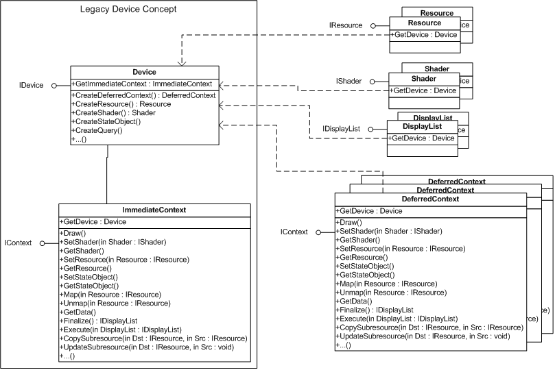
The main aspects to notice are: the separation of IDevice from IContext (as IContext is expected to be implemented by two types of Contexts), the concept of a single Immediate Context per Device, the possibility of multiple Deferred Contexts, the Command List object types, and all the new methods that deal with these new objects. It is not expected that Map, Unmap, and GetData will work on a Deferred Context, while Finalize will not work on the Immediate Context. Further details and options are provided later.
D3D11 allows creation routines to be thread re-entrant, as highlighted in the diagram by grouping such methods on the IDevice interface. This is not accomplished with coarse-grained critical sections. Fine-grained critical-sections are required internally, when necessary. Ideally, no internal synchronization needs to occur; but that is probably not realistic. Not only can one thread be rendering (i.e. calling Draw) while another thread is calling CreateShader; but two threads can be calling CreateShader, while a third thread calls CreateResource, and a fourth is rendering, etc. Due to symmetry, destruction of objects will also be re-entrant. However, the typical destruction of an object goes through multiple stages to keep destruction performant. See Deferred Destruction(6.4.3) for details.
In the D3D10 timeframe, the majority of drivers treated Initial Data passed to the Create functions equivalent to using UpdateSubresource, which is technically a rendering command that naturally presents obstacles for separating creation and rendering. In addition, the UpdateSubresource path would typically force the resource to be faulted into video memory. With changes to the OS kernel, the driver can use the Map/ Unmap path for Initial Data; but this path is unavailable for both Vista and Windows 7. Unfortunately, drivers are required to significantly change their current implementation surrounding this feature, in order to concurrently upload initial data without significantly perturbing the render thread/ frame rate. This is viewed as short-term pain, until the desired kernel changes are available, with an unknown duration for short-term.
Section Contents
(back to chapter)
6.3.1 Overview
6.3.2 Fire and Forget Model, No Feedback
6.3.3 No Context State Inheritance
6.3.4 No Context State Aftermath
6.3.5 Object State Inheritance & Aftermath
6.3.6 Query Interactions
6.3.7 Nested Command Lists
6.3.8 Allow Map Write on Resources with Restriction
6.3.9 Application Immutable, but Patching is Still Required
The concept of a Command List has been around in other graphics APIs, and partially supported by features in previous versions of Direct3D. Instead of immediately executing graphics commands (or giving the impression of such a model), the graphics commands are recorded for execution later. In the overview, the Deferred Context represents the facility to generate Command Lists. Command Lists work well when supporting multi-core CPUs. Command Lists can be generated by separate threads, although they must be manually executed via the render thread using the Immediate Context. The threading model is that a Context (either Immediate or Deferred) cannot be manipulated by more than one CPU thread simultaneously. Two Contexts, however, can be manipulated simultaneously, in parallel with each other, etc. After generation, a Command List can be used multiple times; but cannot be altered by the application explicitly. The interface for a Deferred Context is generally the same as the Immediate Context, with some exceptions. After work has been built up with a Deferred Context, the Command List must be generated by invoking Finalize. By default, Finalize will leave the Deferred Context in a zombie state, waiting for the Deferred Context to be destroyed. However, there will be an option to reset the Deferred Context and allow a new sequence of commands to be recorded, effectively re-creating the Deferred Context. If specialized IContext methods designed for the Immediate Context are invoked off a Deferred Context, they fail; and vice versa.
Since a Deferred Context is building up a deferred timeline for the GPU, the CPU must restrict itself to only sending data to the GPU in a fire-and-forget manor. Deferred Contexts cannot get any feedback from the GPU. Therefore, Resources cannot be Mapped, allowing read access. Query data cannot be retrieved, etc. Such operations can only be done by the rendering thread manipulating the Immediate Context, as the GPU is actually able to make forward progress and resolve the dependencies on data that the CPU requires.
State Inheritance refers to the ability of the Command List to inherit the current state of the Immediate Context when executed. No Immediate Context state (such as bound render targets nor shaders) can be inherited by the Command List. The state of the Deferred Context always starts out in the default Context state (i.e. equivalent to giving the new Deferred Context ClearState, as its first command or equivalent to the Immediate Context state immediately upon creation).
When a Command List is actually scheduled/ executed on either the Immediate or Deferred Context, the state of the Context (such as bound render targets and shaders) will altered afterward. The state of the Context will revert to the default Context state (ie. equivalent to executing ClearState implicitly immediate after Command List execution).
While Command Lists and the Immediate Context state are effectively sheltered from each other, there is a form of Inheritance and Aftermath that needs to occur to make Command Lists useful: Resources and Query contents, etc. When a Command List executes on the Immediate Context, it inherits and can change the global state of objects, such as texture data, constant buffer data, and query data. Therefore it is possible to generate Command Lists that conditionally do different things, with creative use of Predicates and Resource data.
Query data can be generated by Deferred Contexts, just as Render Target data is generated; and Queries can be wrapped around Command List execution. However, there are some problematic cases that need to be handled, assuming the Query syntax remains unchanged.
First, for Queries that have a Beginning and an End, like Predicates, such bracketing must stay local to a particular Context (i.e. Begin & End must occur within same command timeline). It is not possible for a Begin to happen on one Context to be matched with an End on another Context or Command List. For example, problematic cases are exposed when a bracketing is begun in the Immediate Context and ended by a Command List, and vice versa. This is not allowed, and is enforced. If a Command List manipulates a Query (where the corresponding Deferred Context called Begin or End on the Query), the Command List execution will not be allowed on a Context where the same Query has only been Begun. In addition, any Queries that have been Begun in the Deferred Contexts but not Ended, are implicitly Ended by the invocation to Finalize.
Second, when the Command List was being generated, was it assumed that the Command List execution could’ve been wrapped by any of the available Queries? This can be particularly troubling if a Query has hardware bugs related to it and needs some form of emulation. For example, if Blts are being emulated by the 3d pipeline, such operations are specified not to affect certain Queries. To satisfy the specification, the driver could poll any actively monitored counters and subtract off the Blt contribution from Query results. Such driver workarounds are hard to adapt to the Blts that may occur in a Command List. This does have implications on Software Command List implementations (i.e. it may not be known until Command List execution whether a software fallback will be leveraged, meaning the Deferred Context may need to build multiple types of Command Lists).
Command Lists can call Command Lists, i.e. Execute can be called on a Deferred Context. Once Command List usage becomes popular, preventing nested Command Lists presents an obstacle to quickly offload code from the Immediate Context to a Deferred Context. Reducing the disparity between Deferred Context authoring and Immediate Context authoring, when possible, removes obstacles to Deferred Context usage. Infinite recursion is prevented naturally due to the separation of Command List and Deferred Context (i.e. in order to execute a Command List, the Deferred Context must be Finalized). This also means that nested Command Lists are finalized before they can be called by other Command Lists. There is no limit on the level of Command List indirection; but a practial limit on how deep can be realistically tested.
Executing a Command List from a Deferred Context has the same State Aftermath as executing it on the Immediate Context: an implicit ClearState occurs. The Query restrictions that exist between Immediate Context and Deferred Context also exist for nested Command Lists.
The restriction that Deferred Contexts cannot Map any Resource presents an obstacle to quickly offload code from the Immediate Context to a Deferred Context. Efficiently written software and middleware inevitably use dynamic resources for quick upload to the GPU. Such software would have separate code-paths in order to be Context-agnostic (i.e. run against an Immediate Context or a Deferred Context) if Map is completely disallowed. However, if the first invocation to Map for a Deferred Context was a discard, and all Map were Write-Only, these resource operations can be captured without conceptual complications. The entire operation can be converted to be analogous to the UpdateSubresource scenario on the same Deferred Context. Reducing the disparity between Deferred Context authoring and Immediate Context authoring, when possible, removes obstacles to Deferred Context usage.
For all practical purposes, the application interprets the Command Lists as immutable, (i.e. constant after creation). However, there are some cases that could require modification of the Command List to some degree behind the scenes. These are forms of Resource renaming, though they are accomplished via different means.
Even if Map were not allowed on the Deferred Context, there are still interactions between Command Lists and discarding Map that requires special attention. Imagine this code sequence:
    pData = pImmediateContext->Map( pDynamicBuffer, DISCARD );
    *pData = 1;
    pImmediateContext->Unmap( pDynamicBuffer );

    pDeferredContext = pDevice->CreateDeferredContext();
    pDeferredContext->CopyResource( pStagingBuffer, pDynamicBuffer );
    pDisplayList = pDeferredContext->Finalize();

    pData = pImmediateContext->Map( pDynamicBuffer, DISCARD );
    *pData = 2;
    pImmediateContext->Unmap( pDynamicBuffer );

    pImmediateContext->Execute( pDisplayList );
    pData = pImmediateContext->Map( pStagingBuffer, 0 );
The contents of the staging Buffer must be 2, not 1.
The following case is similar to Dynamic Buffers. Even though Present is not allowed on the Deferred Context, there are still interactions between Command Lists and Present that requires special attention. Present rotates the identities of the back buffers, which naturally must affect any Command List that contains references to the Back Buffers.
Resource read-after-write-hazards and other similar issues still need attention. One Command List could be executed which read from a Resource after another Display List that was executed which wrote to the same Resource. It may be feasible to do full pipeline flushes between the Command Lists which are used to achieve multi-CPU thread parallelism. A dual core probably only will execute one of these Command Lists per frame. But, Command Lists which are re-used will have a tendency to be smaller and used many times per frame. Full pipeline flushes may not be acceptable for such Command Lists.
Section Contents
(back to chapter)
6.4.1 Overview
6.4.2 Thread Re-entrant Callback Routines
6.4.3 Deferred Destruction
6.4.4 Context Local Storage Handles
6.4.5 Software Command List Assistance
The need to make certain DDI entry points thread re-entrant implies an increased awareness of threading at the DDI, and naturally, a myriad of changes to keep things efficient and reduce the propensity for bugs. With the increased usage of critical sections come the increased chances for deadlocks. For example, in D3D10, there was a well-defined ordering that critical sections must be acquired and released in, to prevent such deadlocks when holding critical sections simultaneously. If the following type of semantics (i.e. can one component hold a critical section during the invocation into another component) do not fall out of the general design of runtime and DDI, then there is increased burden of documentation and testing. If the API and callbacks could be designed such that the user mode driver needs no synchronization, internally, ensuring no deadlocks occur should be much easier.
With multiple threads in the user mode driver at one time, the DDI callbacks must be thread-safe. The DDI callbacks are generally thin wrappers around the thunks provided by DXGI. They isolate the driver from kernel handles and kernel function signatures. The kernel function signatures may change from OS release to OS release. D3D11 DDI callbacks have identical function signatures and functionality as D3D10 DDI callbacks. However, in contrast to D3D10 DDI callbacks, D3D11 DDI callbacks are designed to be free-threaded when used with a driver that support thread-safe creation. Callbacks used to satisfy creations will need to be thread re-entrant or provide thread re-entrant counterparts. Ideally D3D11 DDI callbacks would be completely free-threaded, but there are few restrictions that still remain. One restriction is that only a single thread can be working against a HCONTEXT at a time. Callbacks that use a HCONTEXT are pfnPresentCb, pfnRenderCb, pfnEscapeCb, pfnDestroyContextCb, pfnWaitForSynchronizationObjectCb, and pfnSignalSynchronizationObjectCb. Thus, if more than one thread is calling these callbacks using the same HCONTEXT, they are required to be synchronized. This is quite natural since these are callbacks that are likely to be called only from the thread that is manipulating the immediate context. Another restriction is that callbacks below are required to be invoked during DDI function calls using the same thread that called the DDI:
pfnDeallocateCb deserves special mention, as it is not required to be called before the driver returns from D3D10DDI_DEVICEFUNCS::pfnDestroyResource for the majority of resource types. Since pfnDestroyResource is a free-threaded function, the driver must defer destruction of the object until it can be efficiently ensured that no existing immediate context reference remains (i.e. that pfnRenderCb is called before calling pfnDeallocateCb). This applies even to shared resources, or any other invocation using HRESOURCE to complement HRESOURCE usage with pfnAllocateCb; but does not apply to primaries.
One of the basic tasks of the API is lifetime management of objects and handles. To stay efficient, the API prefers that object and handle destruction is deferred and amortized by default. Typically, deferment means until the GPU is no longer using the object. However, here, the term is meant to represent that the CPU is no longer using an object. The API will not delete an object whose ref count drops to 0. Instead, every flush of a command buffer gives the API an amortized opportunity to check to find those objects whose ref count is 0 and are no longer bound to the Immediate Context. This list of handles to delete can be provided to the driver to assist with an efficient flush. There may be additional mechanisms to destroy handles to suit all the needs of the API; but the guarantee will still exist that destroyed handles will not be currently bound to any context.
The user mode driver has to manipulate data local to each object/ handle involved, in order to interact with the driver models. For example, allocation lists have to be built up to accompany command buffer submissions. Because all objects are now becoming nearly process-global, modifying data directly associated with these objects would require synchronization. It is more efficient to have an area of memory strongly associated with each object, but also local to a context, allowing CPU thread modification of memory without synchronization. The user mode driver can provide the size required for such memory, to gain efficiency with anything the runtime needs to allocate also.
The runtime provides a default implementation of the Deferred Context that will emulate Command List support. Even if all the API features can be supported directly in hardware, this does help bootstrap a driver faster. In addition, it can possibly be leveraged for debugging.
Chapter Contents
(back to top)
7.1 Instruction Counts
7.2 Common instruction set
7.3 Temporary Storage
7.4 Immediate Constants
7.5 Constant Buffers
7.6 Shader Output Type Interpretation
7.7 Shader Input/Output
7.8 Integer Instructions
7.9 Floating Point Instructions
7.10 Vector vs Scalar Instruction Set
7.11 Uniform Indexing of Resources and Samplers
7.12 Limitations on Flow Control and Subroutine Nesting
7.13 Memory Addressing and Alignment Issues
7.14 Shader Memory Consistency Model
7.15 Shader-Internal Cycle Counter (Debug Only)
7.16 Textures and Resource Loading
7.17 Texture Load
7.18 Texture Sampling
7.19 Subroutines / Interfaces
7.20 Low Precision Shader Support in D3D
Summary of Changes in this Chapter from D3D10 to D3D11.3
Back to all D3D10 to D3D11.3 changes.(25.2)
Full details of the Shader models for each shader stage are provided in dedicated sections elsewhere in the spec. What follows is a discussion of a few general items (not an exhaustive list) that are common to all of the Shader models.
There are no limits on total shader program length or execution time (accounting for loops and subroutines), aside from any limitations in what may be expressed in the shader token format. Clearly longer programs will degrade in performance, but D3D11.3 currently does not specify how steeply performance will degrade relative to program length or execution time given that there are so many variables that might affect performance.
Aside from a few exceptions, the instruction set for all the shader stages are identical. The exceptions are confined to instructions that only make sense in a given Shader unit. For example the sample instruction computes LOD based on derivatives, so sample and sample_b (sample with LOD bias) are only relevant in the Pixel Shader where derivatives are present, while sample_l (sample at selected LOD) and sample_d (sample with application-provided derivatives) is available in all stages.
Temporary storage is composed of a single Element type, which is a 4-tuple of untyped 32-bit quantities. Temporary storage consists of two classes of storage: registers, which are non-indexed single elements; and arrays, which are indexable 1D arrays of elements. Temporary storage is read/write, and is uninitialized at the start of a Shader execution instance. Reads of temporary storage that has not been previously written within a Shader execution instance return undefined values, but cannot return data outside of the address space of the device context.
Temporary registers are declared(22.3.35) r#, and can be used as a temporary operand in D3D11.3 instructions.
Temporary arrays are declared(22.3.36) as x#[n], where “n” is the array length (indexed with 0..n-1). Temporary arrays must be indexed by an r# scalar, statically indexed x# scalar, and/or and optional immediate constant (literal), and can have only one level of index nesting (e.g. x0[x1[r0.x+1].x+1] is not legal, but x0[x1[1].x+1] is legal). A temporary array reference, x#[?], can be used as a temporary operand in D3D11.3 instructions (i.e. anywhere an r# can be used). Out of bounds access to x#[?] is undefined, except that data outside the GPU process context is never visible.
The total quantity of temporary storage per Shader execution instance is 4096 elements, which can be utilized in any combination of registers and arrays. i.e. the total number of r# and x# declared must be <= 4096.
Note that the namespace for r# and x# (the #) are independent. e.g. Suppose r2 and x2[5] are declared. They are independent, but together both count as 6 units of storage against the limit of 4096 temporary registers.
To provide a run-time stack, a program allocates a temporary array of a fixed size. The program should provide its own stack bounds checking, e.g., skip calls if the stack push would exceed the array bounds.
There is no limit on the total number of times a temp registers (the same one or different ones) that can appear in a single instruction or in a shader.
For any instruction source argument that is capable of taking a temporary register, it is also permitted to supply 32-bit immediate scalar or 32-bit immediate 4-vector in the Shader code. Only at most one source operand per instruction may be specified using an immediate value (having up to 4 components). Immediate scalar values used in indexing of registers can only be used once per indexed operand in an instruction, and but these immediate values do not count against the limit of one immediate as a raw source operand. e.g. "add r0, v[1 + r0.x], float4(1.0f,2.0f,3.0f,4.0f)" is valid, since there is only one immediate source operand present (the float4), with the value 1 in the indexing of v[] not counting against the limit.
If a source operand is a Constant Buffer reference (see Constant Buffers below), the reference to a Constant Buffer DOES count against the same limit as immediate values. This allows implementations to provide immediate values through the same hardware path as Constant Buffers if desired. e.g. "add r0, cb0[r1.x], float4(1.0f,2.0f,3.0f,4.0f)" is invalid, since both an immediate value is used as well as a Constant Buffer read in the same instruction.
There is no limit on the total number of times immediate constants can appear in a single instruction or in a shader.
There are 15 slots for ConstantBuffers that can be active per Pipeline stage. Indexing across ConstantBuffers is not permitted. A given ConstantBuffer is accessed as an operand to any Shader operation as if it is an indexable read-only register in the Shader. Unlike other Buffer binding locations in the pipeline, Constant Buffers do not allow Buffer offsets nor custom strides. The stride of the Buffer is assumed to be the Element width of R32G32B32A32_TYPELESS; and the first Element in the Buffer (at Buffer offset zero) is assumed to constant #[ 0 ], when referenced from the Shader.
In Shader code, just as a t# register is a placeholder for a Texture, a cb# register is a placeholder for a ConstantBuffer at "slot" #. A ConstantBuffer is accessed in a Shader using: cb#[index] as an operand to Shader instructions, where 'index' can be either an r# or statically indexed x# containing a 32-bit unsigned integer, an immediate 32-bit unsigned integer constant, or a combination of the two, added together. e.g. "mov r0, cb3[x3[0].x+6]" represents moving Element 7 from the ConstantBuffer assigned to slot 3 into r0, assuming x3[0].x contains 1.
There is no limit on the total number of times constant buffer reads (from any buffer and location in the buffer) that can appear in a single instruction or in a shader.
The declaration of a ConstantBuffer (cb# register) in a Shader includes the following information:
Out of bounds access to ConstantBuffers returns 0 in all components. Out of bounds behavior is always with respect to the size of the buffer bound at that slot.
If the constant buffer bound to a slot is larger than the size declared in the shader for that slot, implementations are allowed to return incorrect data (not necessarily 0) for indices that are larger than the declared size but smaller than the buffer size.
Fetching from a ConstantBuffer slot with no Buffer present always returns 0 in all components for all indices.
With this set of information, different hardware implementations sporting varying degrees of optimization for ConstantBuffer access may make informed decisions about how to compile access to the ConstantBuffer into Shader code. Compiled shaders must never have to recompile just because different ConstantBuffers get bound to the Shader, as the necessary characteristics have been statically declared. Runtime validation (at least in debug) will ensure that the Shader code and the sizes of bound ConstantBuffers satisfy the declarations.
The priorities assigned to ConstantBuffers assist hardware in best utilizing any dedicated constant data access paths/mechanisms, if present. There is no guarantee, however, that accesses to ConstantBuffers with higher priority will always be faster than lower priority ConstantBuffers. It is possible that a higher priority ConstantBuffer could produce slower performance than a lower priority ConstantBuffer, depending on the declared characteristics of the buffers involved. For example an implementation may have some arbitrary sized fast constant RAM not large enough for a couple of high priority ConstantBuffers that a Shader has declared, but large enough to fit a declared low priority ConstantBuffer. Such an implementation may have no choice but to use the standard (assumed slow) texture load path for large high priority ConstantBuffers (perhaps tweaking the cache behavior at least), while placing the lowest priority ConstantBuffer into the (assumed fast) constant RAM.
Applications are able to write Shader code that reads constants in whatever pattern and quantity desired, while still allowing different hardware to easily achieve the best performance possible.
In addition to the aforementioned 15 slots for Constant Buffers, every shader program can declare(22.3.4) a single Immediate Constant Buffer with up to 4096 4-vector values. The data is tied to the shader program permanently, but otherwise behaves (gets accessed) by the shader exactly the same way as Constant Buffers.
There is no limit on the total number of times immediate constant buffer reads (from any location the buffer) can appear in a single instruction or in a shader.
The application is given control over the data type interpretation for Shader outputs (i.e. writing raw integer values vs. writing normalized float values) by simply choosing an appropriate format to interpret the output resource's contents as. See the Formats(19.1) section for detail.
Details on Shader input/output registers (indeed all registers) are provided in the sections dedicated to each Shader unit elsewhere in the spec.
One thing in common about input/output registers for all shaders is that if they are declared(22.3.30) to be dynamically indexable from the shader, and the shader indexes them out of the declared range, results are undefined, although no data from outside the GPU process context is never visible.
Section Contents
(back to chapter)
7.8.1 Overview
7.8.2 Implementation Notes
7.8.3 Bitwise Operations
7.8.4 Integer Arithmetic Operations
7.8.5 Integer/Float Conversion Operations
7.8.6 Integer Addressing of Register Banks
There is a collection of instructions available to Shaders which are dedicated to performing integer arithmetic and bitwise operations. Operands and output registers for integer instructions can be any of the register classes available to the floating point instructions. There is no data type associated with registers; Shader instructions determine how the data stored in registers is interpreted. Integer instructions simply assume that the data being read from operands and written to the destination are all 32-bit values (unsigned or signed 2's complement, depending on the instruction).
Shader register storage is made up of 32-bit*4-component quantities, and integer arithmetic on these registers is required to be performed at full 32 bit in all cases.
The bitwise instructions are listed in the Bitwise Instructions(22.11) sub-section of the full instruction listing.
See the Integer Arithmetic Instructions(22.12) sub-section of the full instruction listing.
There is no implicit conversion between floating-point and integer values. Contents of registers are interpreted as float or ints by the particular instruction being executed. Two instructions exist that allow explicit conversions to be performed, listed in the Type Conversion Instructions(22.13) sub-section of the full instruction listing.
Integer offsets for reads from register banks are available. These offsets must be scalar values (i.e. a select swizzle must be used to select one component of any vector-valued register used as an index) and are considered to be unsigned 32 bit values.
This indexing mechanism applied to indexable x# registers allows compilers to generate stack-like behavior for Shader subroutines.
An example syntax for indexing is:
mov r1, cb7[3+r2.x]
This instruction assumes that an unsigned 32-bit integer value exists in r2.x, and uses that value to offset into ConstantBuffer 7, starting from location 3 in the ConstantBuffer. Thus, if r2.x contains integer value 2, entry 5 of ConstantBuffer 7 would be referenced.
Floating point instructions must follow the D3D11.3 Floating Point Rules(3.1).
A listing of all floating point instructions can be found here(22.10).
Instructions are provided for rounding floating point values to integral floating point values:
round_ne(22.10.14) (nearest-even)
round_ni(22.10.15) (negative-infinity)
round_pi(22.10.16) (positive-infinity)
round_z(22.10.17) (towards zero)
The D3D intermediate language (IL) and register model are 4-vec oriented. Since this does not constrain hardware implementation (vector vs scalar) too much, this convention will carry forward until a good reason to switch paradigms surfaces. It is known that many implementations actually happen to operate on scalars or combinations of layouts even now.
One area where the vector assumption seems to materially impact data organization is the indexing of registers such as inputs or outputs – the indexing happens across registers. If it is important to be able to express cleanly how to index through an array of scalars, this could be an example of an argument for switching the IL to be completely scalar.
Section Contents
(back to chapter)
7.11.1 Overview
7.11.2 Index Range
7.11.3 Constant Buffer Indexing Example
7.11.4 Resource/Buffer Indexing Example
7.11.5 Sampler Indexing Example
7.11.6 Resource Indexing Declarations
Shaders have bindpoint arrays for various classes of read-only input resources: Constant Buffers (cb), Texture/Buffers (t), Samplers (s).
D3D11 allows all of these to be dynamically but uniformly indexed from a shader, whereas previously none of them were indexable.
As with indexing of other types, such as indexable temps (x#), the dynamic index can be either an r# or statically indexed x# containing a 32-bit unsigned integer, an immediate 32-bit unsigned integer constant, or the combination of the two, added together.
The constraint on the indexing of resources or samplers is that the index must be uniform. That is, the computed index must be the same at that point in the lockstep execution of the program for all invocations of the shader within the Draw*() call. If due to flow control, some of the lockstep shader invocations are inactive, the computed index in those shaders is ignored and therefore cannot cause a violation of the uniform indexing constraint on all the active invocations.
The HLSL compiler will enforce this behavior and driver compilers must not break it either. Violations of the uniform indexing constraint would be a result of an HLSL compiler bug or a driver compiler bug only, and in such cases the indexing results are undefined.
Out of bounds resource indexing produces the same result as if accessing a slot with no resource bound.
In particular note that with Constant Buffers, there are 14 API-visible Constant Buffer slots (a couple of other slots are reserved for various purposes). The valid indexing range for Constant Buffers is therefore [0..13], and accesses out of that range behave as if accessing a slot with no Constant Buffer bound.
Out of bounds indexing of the Samplers (s#) results in undefined behavior.
Suppose x3[0].x contains 4 and x4[2].y contains 5. The following mov instruction:
mov r0, cb[x3[0].x+6][x4[2].y+9]
is therefore equivalent to:
mov r0, cb[10][14]
which means read a 32-bit * 4-vector from location [14] in the ConstantBuffer, at ConstantBuffer bind point [10] (0-based counting).
The uniform dynamic indexing of which Constant Buffer to read from is what was not supported previously. Dynamic indexing within the Constant Buffer itself has always been supported.
Suppose x3[0].x contains 4. The following ld instruction:
ld r0, r1, t[x3[0].x+6], texture2D
is equivalent to:
ld r0, r1, t[10], texture2D
Note the "texture2D" at the end is also a new requirement, whereby all ld/sample instructions will indicate which Shader Resource View type is to be sampled.
Suppose x3[0].x contains 4 and x4[2].y contains 5. The following sample instruction:
sample r0, r1, t[x3[0].x+6], s[x4[2].y+9], textureCubeArray
is equivalent to:
sample r0, r1, t[10], s[14], textureCubeArray
Shader declarations from Shader Model 4.x for individual resources, constant buffers and samplers remain the same in Shader Model 5.0. These are particularly informative for parts of shader code that reference these objects directly, just as before.
However, all instructions that reference texture objects (t#) now specify the view dimension (e.g. textureCubeArray) as a literal parameter. This is redundant when indexing is not used, since the up-front declaration of each t# has a view dimension, but useful when indexing is used.
A flow control block is defined as an if(22.7.1) block, loop(22.7.4) block, or switch(22.7.18) block. Flow control blocks can nest up to 64 deep per subroutine (and main). Behavior of flow control instructions beyond this nesting limit is undefined.
Subroutines can nest up to 32 deep. If there are already 32 entries on the return address stack and a "call" is issued, the call is skipped over.
For Typed memory views, the number of components in an address when accessed by a shader instruction is determined by the number of components in the resource dimension. Each address component is an unsigned 32-bit integer element index.
For Raw memory views, the address is a single component unsigned 32-bit integer byte offset from the beginning of the view. The addresses must be 32-bit aligned. If an unaligned address is specified for an operation involving a write, the entire contents of the UAV(5.3.9) being written, or all of Thread Group Shared Memory (in the Compute Shader(18)) - whichever is being accessed - becomes undefined. If an unaligned address is specified for an operation involving a read, an undefined result is returned to the shader. It is invalid for implementations to perform the access as if there were no 32-bit alignment constraints.
For Structured memory views, the address is two unsigned 32-bit integer values. The first value is the struct index, and the second value is a byte offset into the struct. The byte offset must be aligned to 32-bits, otherwise the same behavior described for misaligned raw memory access above applies.
Each memory access instruction defines its behavior for out of bounds accesses, with distinctions for the memory location being accessed (UAV vs SRV vs Thread Group Shared Memory), and the layout (raw vs structured vs typed). See the documentation of individual instructions for details. The behaviors are similar for similar classes of instructions – e.g. all atomics have the same out of bounds behavior, all immediate atomics (which return a value to a shader) have their own consistent out of bounds access behavior, etc.
Section Contents
(back to chapter)
7.14.1 Intro
7.14.2 Atomicity
7.14.3 Sync
7.14.4 Global vs Group/Local Coherency on Non-Atomic UAV Reads
The types of memory accesses included in the scope of this chapter are: to Unordered Access Views(5.3.9) (UAVs, u#), available to the Compute Shader(18) and Pixel Shader(16), as well as Thread Group Shared Memory (g#), available to the Compute Shader.
The D3D11 Shader Memory Consistency Model is weak/relaxed, as generally understood in existing architectures and literature. Loosely, this means the program author and/or compiler are responsible for identifying all memory and thread synchronization points via some appropriately expressive labeling.
This section outlines how this weak/relaxed Memory Consistency Model appears to function from the point of view of D3D software.
An atomic operation may involve both reading from and then writing to a memory location. Atomic operations apply only to either u# (Unordered Access Views) or g# (Thread Group Shared Memory).
It is guaranteed that when a thread issues an atomic operation on a memory address, no write to the same address from outside the current atomic operation by any thread can occur between the atomic read and write.
If multiple atomic operations from different threads target the same address, the operations are serialized in an undefined order.
Atomic operations do not imply a memory or thread fence. Fence operations (dubbed "sync") are introduced below. If the program author/compiler does not make appropriate use of fences, it is not guaranteed that all threads see the result of any given memory operation at the same time, or in any particular order with respect to updates to other memory addresses.
Atomicity is implemented at 32-bit granularity. If a load or store operation spans more than 32-bits, the individual 32-bit operations are atomic, but not the whole.
Limitation: Atomic operations on Thread Group Shared Memory are atomic with respect to other atomic operations, as well as operations that only perform reads ("load"s). However atomic operations on Thread Group Shared Memory are NOT atomic with respect to operations that perform only writes ("store"s) to memory. Mixing of atomics and stores on the same Thread Group Shared Memory address without thread synchronization and memory fencing between them produces undefined results at the address involved. This limitation arises because some implementations of loads and stores do not honor the locking semantics for implementing atomics. It turns out this has no impact on loads, since they are guaranteed to retrieve a value either before or after an atomic (they will not retrieve partially updated values, given they are all defined at 32-bit quanta). However store operations could find their way into the middle of an atomic operation and thus have their effect possibly lost.
Note that there is no such limitation on atomics to UAV memory; atomic operations on UAV memory is atomic both with respect to other atomic operations as well as loads and stores.
A sync(22.17.7) instruction is included in the Shader IL for Pixel Shader and the Compute Shader.
This provides memory fence semantics at various scopes, and optional thread group synchronization semantics (the latter only applies to the Compute Shader). For details, including some discussion of the implications see the description of the sync(22.17.7) instruction.
Typical implementations will have a cache hierarchy to improve read access performance on UAV(5.3.9) accesses. A constraint that some implementations have with the first stage in this cache hierarchy is that, in addition to operating at per-thread-group scope only, the cache does not have an efficient way of being synchronized with writes or atomics that have happened by other thread groups. Such behavior only surfaces as an issue for applications when cross-thread-group communication needs to be performed involving data loads. In this case, the hardware basically needs to know that it must bypass the first stage of caches on loads, reaching out to a more global memory so that the cross thread-group communication can function. D3D allows applications specify this cross-thread-group communication intent as follows.
If a Compute Shader(18) thread in a given thread group needs to perform loads of data that was written by atomics or stores in another thread group, the UAV slot where the data resides must be tagged upon declaration in the shader as "globally coherent", so the implementation can ignore the local cache. Otherwise, this form of cross-thread group data sharing will produce undefined results.
Atomic read-modify-write operations do not have this constraint (even though a part of the operation is a read/load), because a byproduct of the hardware honoring atomicity is that the entire system sees the operation, whereas simple loads on some implementations may only go to a local cache that has no knowledge of external updates.
If a UAV is not declared as "globally coherent", it is only "group coherent", which means loads can only see data written by stores and atomics in other threads in the same thread group. The affected hardware knows it can make use of its thread-group specific caching for loads, since writes to the memory only came from the current thread group. A UAV tagged as "globally coherent" is also inherently obviously "group coherent", although the affected hardware would not use its local cache. As such, the "globally coherent" flag should only be specified when necessary.
As a reminder though, to guarantee coherency on UAV accesses on all implementations, not only must shaders make the global vs group scope distinction discussed here upon UAV declaration, but they must also make appropriate use of memory and/or thread barriers ("sync_*" in the IL) as needed within in the shader to enforce proper ordering of operations by individual threads as seen by others. In addition, the "sync" operation has options for memory barriers that also distinguish between global vs group scope, but that control is separate from the topic of this section, and may not be exposed until a later time, as discussed in the sync instruction definition.
Back to issue of global vs group coherency on non-atomic UAV reads. Importantly, for many scenarios where cross thread-group communication or reduction (such as histograms) can be accomplished using only atomic operations (no cross thread-group loads involved), there is no problem since atomic operations are implemented by all hardware in a globally coherent way, regardless of whether the UAV has been tagged as "globally coherent" or not.
In the Pixel Shader(16), if a UAV is not declared as "globally coherent", it is only "locally coherent". "Local coherency" is the Pixel Shader’s equivalent of the Compute Shader’s "group coherency", except having scope limited only to a single Pixel Shader invocation. This indicates that the Pixel Shader is not doing any cross-PS-invocation communication involving simple load operations. Note, however, that in the Pixel Shader just like in the Compute Shader, atomic read-modify-write operations are always globally coherent. Indeed it is likely to be rare for a Pixel Shader or perhaps even the Compute Shader to need to declare a UAV as "globally coherent", given that atomic operations, which are always globally coherent, might provide the most practical mechanism for cross-PS-invocation or cross-group operations.
To assist comparisons of algorithms running on GPUs during application development, a cycle counter can be read into shaders. The cycle counter is a 64-bit unsigned integer.
The cycle counter appears as an additional 2*32-bit (64 bit total) input register type that can declared in any version 5.0+ shader. There are currently no native 64-bit integer arithmetic operations in shaders, although it is simple enough to emulate this. It may be fine for shaders to just look at the low 32-bits of the counter – this can be requested in the shader. Applications may also export the measurements using standard shader outputs for later analysis such as on the CPU.
The counter is an implementation-dependent measure of cycles in the GPU engine, requiring care to interpret it usefully.
For this discussion, consider a shader "invocation" to be a single execution of one shader program from beginning to end. For the Compute Shader however, an "invocation" is a single thread-group’s execution – e.g. the lifespan of the contents of thread-group shared memory.
The initial value of the counter is undefined.
A single reading of the cycle counter is meaningless. But any shader invocation can poll the counter value any number of times.
Computing a delta from cycle counter readings within a shader invocation is meaningful.
Computing a delta from cycle counter readings across separate shader invocations is not meaningful on all hardware. Developers must obtain information directly from IHVs about whether this is meaningful.
The only IHV agnostic approach to interpreting the counters is to limit calculation of deltas to within a given shader invocation, and only make comparisons of deltas within or between shader invocations.
There are plenty of reasons why test runs will execute differently. The obvious one is that execution of a shader can be interrupted by thread switching, so delta measurements will be arbitrarily larger than the number of cycles spent executing instructions in a given thread.
There is no supported way to find out the frequency of the counter. There is no way to correlate this shader internal counter with external timers such as asynchronous time queries. The counter measurements cannot be correlated with measurements on different hardware by other hardware vendors or even necessarily the same vendor.
If a GPU’s speed changes, such as for power saving, there is no way to know this happened, or its effect on cycle measurements.
Beyond these hints about the care needed to interpret the counter, the onus is on developers to research the properties of new hardware designs that may affect measurements.
The HLSL shader compiler and driver compilers must treat reads of the cycle counter as barriers. Instructions can’t be moved across a counter read, and counter reads can’t be merged.
The runtime enforces that shaders using this feature can only be created on a system with debug layer enabled. The debug layer is not allowed to be redistributed to end-user machines. The point is that shaders that use this counter are not intended to be shipped.
This feature will not be tested on hardware by WHQL, except perhaps simply checking that drivers do not crash. Microsoft will test that the HLSL compiler output is correct.
A new input register, vCycleCounter(22.3.29), can be declared in any version 5_0 (and beyond) shader:
dcl_input vCycleCounter.{x|xy}.
Reading x yields the 32 LSBs of the 64-bit count, and reading y yields the 32 MSBs.
This register can only be used as the source to a mov instruction, e.g. mov r0.w, vCycleCounter.x.
Up to 128 Resources (e.g. Buffer, Texture1D/2D/3D/Cube) can be active per Pipeline stage. A Resource binding is a representation of a Resource's base pointer (and other data such as size and pixel layout) and is independent of the samplers.
A texture out of a set of bound textures cannot be selected via Shader indexing, however Texture1D/2D/3D resources with an Array dimension > 1, or TextureCube (which has an Array dimension of 6), allow indexing along the array axis from within Shader code.
Textures can only have a single Element format. Likewise, Buffers used as input to Shaders can also only have a single Element format, and have an implied data stride equal to the Element size. A single Buffer (or Texture) could be set to multiple input slots simultaneously, with different Element formats and/or offsets, however because Buffers bound as Shader inputs have their data stride implied by the Element format, it is not possible to describe "Array-of-Structures" style layouts in Buffers bound at Shader input. This unlike the Input Assembler Stage, where multiple element Buffers are permitted, and Element offsets and strides can be defined Buffers freely.
Data from textures is accessed in shaders via the load (ld) and sample instructions. The ld instruction provides a simple read and (optional) float32 conversion of texture data using integral addresses, while the sample instructions use normalized floating point addressing and perform filtering in addition to the format conversion.
The load operation performs a non-filtered read of resource data. See the ld(22.4.6) instruction definition for details.
Multisample resources can be set as shader inputs, which allows individual samples to be read by the shader. Support for multisample shader reads has the following restrictions:
See ld(22.4.6) and dcl_resource(22.3.12) definitions for details.
Section Contents
(back to chapter)
7.18.1 Overview
7.18.2 Samplers
7.18.3 Sampler State
7.18.4 Normalized-Space Texture Coordinate Magnitude vs. Maximum Texture Size
7.18.5 Processing Normalized Texture Coordinates
7.18.6 Reducing Texture Coordinate Range
7.18.7 Point Sample Addressing
7.18.8 Linear Sample Addressing
7.18.9 Texture Address Processing
This section describes the mechanics of sampling Texture1D/2D/3D/Cube resources using filtering. The simplest form of sampling a texture is point sampling, supported for all data formats, however more complex filtering operations are only available to some formats, indicated in the format list in the Formats(19.1) section.
The behaviors described here are obtained via the the various sample* instructions, such as sample(22.4.15). See the specs for those instructions for further details that complement this section.
Unless otherwise noted, all texture sampling address operations are performed according to the arithmetic processing rules described in the Basics(3) section.
Texture filtering theory or historical background is NOT provided in this spec.
Note that details of all required texture filtering algorithms are not fully/exactly specified for this version of D3D11.3; the specs below only explicitly define a subset of all filtering features available in D3D11.3.
Samplers identify filtering modes and other sampler state, described below. Samplers are not indexable from within shaders. There are 16 samplers "slots" per Pipeline stage, to which "Sampler Objects" can be arbitrarily assigned/reassigned.
The state for a sampler is encapsulated in a "sampler object", up to 4096 of which can be created through the API. At the time a sampler object is created, all of its state must be chosen permanently, and can never be changed. These sampler objects can be arbitrarily assigned to any of the 16 "sampler slots" at each of the Shader stages (a single sampler object is allowed to be assigned to multiple sampler slots, even on multiple pipelines stages simultaneously, if desired.
The reason Sampler Objects are statically created, and there is a limit on the number that can be created, is to enable hardware to maintain references to multiple samplers in flight in the Pipeline, without having to track changes or flush the Pipeline, which would be necessary if Sampler Objects were allowed to be edited.
typedef enum D3D11_FILTER
{
    // Bits used in defining enumeration of valid filters:
    // bits [1:0] - mip: 0 == point, 1 == linear, 2,3 unused
    // bits [3:2] - mag: 0 == point, 1 == linear, 2,3 unused
    // bits [5:4] - min: 0 == point, 1 == linear, 2,3 unused
    // bit  [6]   - aniso
    // bit  [7]   - comparison
    // bits [8:7] - reduction type:
    //                0 == standard filtering
    //                1 == comparison
    //                2 == min
    //                3 == max
    // bit  [31]  - mono 1-bit (narrow-purpose filter) [no longer supported in D3D11]

    D3D11_FILTER_MIN_MAG_MIP_POINT                              = 0x00000000,
    D3D11_FILTER_MIN_MAG_POINT_MIP_LINEAR                       = 0x00000001,
    D3D11_FILTER_MIN_POINT_MAG_LINEAR_MIP_POINT                 = 0x00000004,
    D3D11_FILTER_MIN_POINT_MAG_MIP_LINEAR                       = 0x00000005,
    D3D11_FILTER_MIN_LINEAR_MAG_MIP_POINT                       = 0x00000010,
    D3D11_FILTER_MIN_LINEAR_MAG_POINT_MIP_LINEAR                = 0x00000011,
    D3D11_FILTER_MIN_MAG_LINEAR_MIP_POINT                       = 0x00000014,
    D3D11_FILTER_MIN_MAG_MIP_LINEAR                             = 0x00000015,
    D3D11_FILTER_ANISOTROPIC                                    = 0x00000055,
    D3D11_FILTER_COMPARISON_MIN_MAG_MIP_POINT                   = 0x00000080,
    D3D11_FILTER_COMPARISON_MIN_MAG_POINT_MIP_LINEAR            = 0x00000081,
    D3D11_FILTER_COMPARISON_MIN_POINT_MAG_LINEAR_MIP_POINT      = 0x00000084,
    D3D11_FILTER_COMPARISON_MIN_POINT_MAG_MIP_LINEAR            = 0x00000085,
    D3D11_FILTER_COMPARISON_MIN_LINEAR_MAG_MIP_POINT            = 0x00000090,
    D3D11_FILTER_COMPARISON_MIN_LINEAR_MAG_POINT_MIP_LINEAR     = 0x00000091,
    D3D11_FILTER_COMPARISON_MIN_MAG_LINEAR_MIP_POINT            = 0x00000094,
    D3D11_FILTER_COMPARISON_MIN_MAG_MIP_LINEAR                  = 0x00000095,
    D3D11_FILTER_COMPARISON_ANISOTROPIC                         = 0x000000d5,
    D3D11_FILTER_MINIMUM_MIN_MAG_MIP_POINT                      = 0x00000100,
    D3D11_FILTER_MINIMUM_MIN_MAG_POINT_MIP_LINEAR               = 0x00000101,
    D3D11_FILTER_MINIMUM_MIN_POINT_MAG_LINEAR_MIP_POINT         = 0x00000104,
    D3D11_FILTER_MINIMUM_MIN_POINT_MAG_MIP_LINEAR               = 0x00000105,
    D3D11_FILTER_MINIMUM_MIN_LINEAR_MAG_MIP_POINT               = 0x00000110,
    D3D11_FILTER_MINIMUM_MIN_LINEAR_MAG_POINT_MIP_LINEAR        = 0x00000111,
    D3D11_FILTER_MINIMUM_MIN_MAG_LINEAR_MIP_POINT               = 0x00000114,
    D3D11_FILTER_MINIMUM_MIN_MAG_MIP_LINEAR                     = 0x00000115,
    D3D11_FILTER_MINIMUM_ANISOTROPIC                            = 0x00000155,
    D3D11_FILTER_MAXIMUM_MIN_MAG_MIP_POINT                      = 0x00000180,
    D3D11_FILTER_MAXIMUM_MIN_MAG_POINT_MIP_LINEAR               = 0x00000181,
    D3D11_FILTER_MAXIMUM_MIN_POINT_MAG_LINEAR_MIP_POINT         = 0x00000184,
    D3D11_FILTER_MAXIMUM_MIN_POINT_MAG_MIP_LINEAR               = 0x00000185,
    D3D11_FILTER_MAXIMUM_MIN_LINEAR_MAG_MIP_POINT               = 0x00000190,
    D3D11_FILTER_MAXIMUM_MIN_LINEAR_MAG_POINT_MIP_LINEAR        = 0x00000191,
    D3D11_FILTER_MAXIMUM_MIN_MAG_LINEAR_MIP_POINT               = 0x00000194,
    D3D11_FILTER_MAXIMUM_MIN_MAG_MIP_LINEAR                     = 0x00000195,
    D3D11_FILTER_MAXIMUM_ANISOTROPIC                            = 0x000001d5
} D3D11_FILTER;

typedef enum D3D11_TEXTURE_ADDRESS_MODE
{
    D3D11_TEXADDRESS_WRAP         = 1,
    D3D11_TEXADDRESS_MIRROR       = 2,
    D3D11_TEXADDRESS_CLAMP        = 3,
    D3D11_TEXADDRESS_BORDER       = 4,
    D3D11_TEXADDRESS_MIRRORONCE   = 5
} D3D11_TEXTURE_ADDRESS_MODE;

typedef struct D3D11_SAMPLER_STATE
{
    D3D11_FILTER                  Filter;
    D3D11_TEXTURE_ADDRESS_MODE    AddressU; // U coordinate address mode
    D3D11_TEXTURE_ADDRESS_MODE    AddressV; // V coordinate address mode
    D3D11_TEXTURE_ADDRESS_MODE    AddressW; // W coordinate address mode
    float                         MinLOD;
    float                         MaxLOD;
    float                         MipLODBias; // (-16.0f..15.99f)
    DWORD                         MaxAnisotropy;  // (0 - 16)
    D3D11_COMPARISON_FUNC         ComparisonFunction; // for Percentage-Closer filter
    float                         BorderColor[4]; // R,G,B,A
} D3D11_SAMPLER_STATE;
See the Sampler Declaration Statement(22.3.34) in the shader instruction reference for a description of which sampler states are honored depending on the choice of Filter setting, and a description of which sampler* instructions in the shader are permitted to reference samplers configured various ways.
The magnitude of normalized-space texture coordinates (allowing for texture tiling) has no effect on the maximum supportable texture dimensions that can be sampled. The only catch is that as the absolute magnitude of a normalized-space texture coordinate gets larger (e.g. large amounts of tiling), floating point dictates that less precision will be available to resolve individual texels in a given tiling of the texture being sampled. Large amounts of tiling of large dimension textures will yield sampling artifacts where float32 precision becomes inadequate. But separate from this tradoff, in order to otherwise achieve decoupling of the magnitude of normalized-space texture coordinates from having any effect on maximum texture dimension that can be sampled given float32 normalized-space addressing, a range reduction to about [-10...10], depending on the scenario, is applied on the texture coordinates.
Details of this range reduction are described later(7.18.6). The reduction happens before scaling texture coordinates by texture size, conversion to fixed point, and final application of Texture Address modes (CLAMP/MIRROR/WRAP etc.) on texel addresses. The range reduction allows the fixed point representation to not have to dedicate storage for the texture tiling. It is important to note that range reduction is a separate step from applying Texture Address mode (although the particular Texture Address mode affects what type of reduction gets used).
Using range reduction to decouple texture coordinate magnitude from supportable texture size has the following implication: The maximum texture dimension possible to be sampled in D3D11.3 is 2^17. This limit is derived starting with 24 bits of float32 fractional precision for the original texture coordinate, subtracting required subtexel precision (8 bits), and subtracting 1 more bit due to the factor of 2 scaling in the reduced range. Of course, the minimum upper limit for filterable texture dimension required to be exposed by all D3D11.3 implementations is far smaller, at only 16384 (see System Limits(21)).
This section describes in general how to convert a normalized texture coordinate to a texture address. The description is based on sampling a Texture1D, but applies equally to Texture2D and Texture3D (and not TextureCubes).
A normalized texture coordinate (U) maps the range [0, 1] to the range [0, numTexelsU], where numTexelsU is the size of a 1D texture in texels. The process of computing a texture address is as follows:
To limit the number of bits needed to store the texture coordinate in fixed point after conversion from floating point, the range of the normalized texture coordinate is reduced to be within [-10,10], depending on the Address mode. This removes the magnitude of texture tiling from the texture coordinate, while not affecting the behavior of texture address wrap modes. The same address mode handling can be applied to the range reduced texture coordinate as the original, producing the same result. The benefit is that the magnitude of texture tiling is not stored in the coordinate at the same time that texture size scaling is performed on the coordinate. This enables far larger texture coordinate range to be handled cleanly than would otherwise be possible without reduction.
Note that the range reductions applied here in some cases leave a bit of extra padding (up to [-10,10] mentioned). This padding allows for the fact that after scaling by texture size, the selection of texels for point or linear sample kernels involves picking texel(s) to the left and/or right of the sample location, so coordinates that are not near the boundaries of the addresing mode must not appear as if they are on the boundary. e.g. Consider Linear sampling a coordinate that straddles a border when in BORDER mode: this needs to pick up the Border Color for 1/2 of the samples and the interior edge of the texture for the other 1/2. However range reduction cannot just clamp to [0..1) for BORDER mode, because it would make coordinates that fall completely into BORDER territory incorrectly behave as if they straddle the border (picking up some contribution of Border Color and interior). Range reduction has to also allow for immediate texel offsets permitted in shader code Range reduction does not change expected texture sampling behavior; it just helps keep the sequence of floating point operations on texture coordinates within manageable range.
The following logic describes how normalized texture coordinate range reduction is performed. (This is different form final Texture Address Processing(7.18.9), which happens a couple of steps later, on scaled coordinates that identify texels.)
Given:
float signedFrac(float f) returns (f - round_z(f)) // round_z : "round towards zero"
float frac(float f) returns (f - round_ni(f))      // round_ni : "round towards negative infinity"

We have:
float ReduceRange(float U, D3D11_TEXTURE_ADDRESS_MODE AddressMode)
{
    switch (AddressMode)
    {
    case D3D11_TEXTURE_ADDRESS_WRAP:
        // The reduced range is [0, 1)
        return frac(U);
    case D3D11_TEXTURE_ADDRESS_MIRROR:
        // The reduced range is (-2, 2)
        return signedFrac(U/2) * 2;
    case D3D11_TEXTURE_ADDRESS_MIRRORONCE:
    case D3D11_TEXTURE_ADDRESS_CLAMP:
    case D3D11_TEXTURE_ADDRESS_BORDER:
        // The reduced range is [-10, 10].
        // Each of these modes might use different tightnesses of reduced range,
        // but since there really is no benefit in that, a one-size-fits-all
        // approach is taken here.
        // Note that the range leaves room for immediate texel-space offsets
        // supported by sample instructions, [-8...7],
        // preventing these offsets from causing texcoords that clearly should
        // be out of range (i.e. in border/clamp region) from falling within
        // range after range reduction.  The point is that range reduction does
        // not have an affect on the texels that are supposed to be chosen.
        if(U <= -10)
            return -10;
        else if(U >= 10)
            return 10;
        else return U;
    }
    return 0;
}
Note that the amount of padding supported here for mirroronce/clamp/border are only feasible for use with point or linear filtering of a texture (a larger kernel becomes more likely to expose the reduced range boundary), including with immediate texel offsets from the shader. Furthermore, complex filters which use point or linear filter taps as building blocks (key example being Anisotropic Texture Filtering) are perfectly compatible with the specified range reduction. The reason is that such filters choose their "taps" by perturbing normalized texture coordinates (e.g. walking the line of anisotropy in Anisotropic Texture Filtering), and thus each pertubed "tap" individually goes through the range reduction described here before application of the usual Point/Linear Sample Addressing logic and Texture Address Processing described below.
Setting aside how sampler state is configured and how mipmap LOD is chosen, consider simply the task of point sampling an Element from a particular miplevel of a Texture1D, given a scalar floating point texture coordinate in normalized space. In the Texture Coordinate Interpretation(3.3.3) section, there is a diagram illustrating generally how a 1D texture coordinates maps to a texel (not accounting for wrapping). Note from the "Texture Coordinate System" diagram shown that texel corners have integral coordinates in texel-space, and so texel centers are at half-units away from the corners. Point sampling selects the "nearest" texel based on the proximity of texel centers to the texture coordinate (keeping in mind that texel centers are at half-units):
For Texture2D and Texture3D Resources, the same rules apply independently on the other dimensions.
For TextureCube Resources, the following occurs:
Similar to the previous section, set aside how sampler state is configured and how mipmap LOD is chosen for now, and consider simply the task of linear sampling an Element from a particular miplevel of a Texture1D, given a scalar floating point texture coordinate in normalized space. Linear sampling in 1D selects the nearest two texels to the sample location and weights the texels based on the proximity of the sample location to them.
texelFetch(tFloorU) * wFloorU +
texelFetch( tCeilU) *  wCeilU
The procedure described above applies to linear sampling of a given miplevel of a Texture2D as well:
texelFetch(tFloorU,tFloorV) * wFloorU * wFloorV +
texelFetch(tFloorU, tCeilV) * wFloorU *  wCeilV +
texelFetch( tCeilU,tFloorV) *  wCeilU * wFloorV +
texelFetch( tCeilU, tCeilV) *  wCeilU *  wCeilV
Performing linear sampling of a miplevel of a Texture3D Resource extends the concepts described above to fetching of 8 texels.
In the case of a TextureCube, see the section regarding TextureCube Edge and Corner Handling(7.18.12)
The sample* instructions provide texture coordinates in normalized floating point form, such that values in [0..1] range span a given dimension of a texture, and values outside this range fall off the borders of the texture. Later in the filtering process, when individual texels are fetched, if the address is outside the extents of the texture, either the address gets mapped back into range by the texture address mode for each component, or the border-color is used. The texture address mode is defined by the AddressU, AddressV, and AddressW members of D3D11_SAMPLER_STATE.
Consider the moment in the process of sampling of a Texture1D just after picking a particular integer address scaledU to fetch a texel from (details on choosing sample locations described elsewhere for various filter modes). Suppose the texel address scaledU falls off the Texture1D, meaning either (scaledU < 0), or (scaledU > numTexelsU - 1), where numTexelsU is the count of texels in the U dimension of the Texture1D. The following pseudocode describes how the setting on D3D11_SAMPLER_STATE member AddressU gets applied on scaledU:
if ((scaledU < 0) || (scaledU > numTexelsU-1))
{
    switch (AddressU)
    {
    case D3D11_TEXADDRESS_WRAP:
        scaledU = scaledU % numTexelsU;
        if(scaledU < 0)
            scaledU += numTexelsU;
        break;
    case D3D11_TEXADDRESS_MIRROR:

        {
            if(scaledU < 0)
                scaledU = -scaledU - 1;
            bool Flip = (scaledU/numTexelsU) & 1;
            scaledU %= numTexelsU;
            if( Flip ) // Odd tile
                scaledU = numTexelsU - scaledU - 1;
            break;
        }
    case D3D11_TEXADDRESS_CLAMP:
        scaledU = max( 0, min( scaledU, numTexelsU - 1 ) );
        break;
    case D3D11_TEXADDRESS_MIRRORONCE:
        if(scaledU < 0)
            scaledU = -scaledU - 1;
        scaledU = max( 0, min( scaledU, numTexelsU - 1 ) );
        break;
    case D3D11_TEXADDRESS_BORDER:
        // Special case: Instead of fetching from the texture,
        // use the Border Color(7.18.9.1).
        bUseBorderColor = true;
        break;
    default:
        scaledU = 0;
    }
}
For Texture2D and Texture3D, all of the above modes apply to the V and W dimensions independently, based on AddressV and AddressW. If any single dimension selects Border Color, then the Border Color(7.18.9.1) is applied.
Border Color values are defined in the DDI via 4 floating point values (RGBA), in linear space. The Border Color used in filtering is snapped to the precision the hardware performs filtering at for the format.
Note that the only components of the BorderColor used by filtering hardware are the ones present in the resource format description.
For example, suppose the resource format is DXGI_FORMAT_R8_SNORM, and BorderColor is needed during a sample operation. In this case only the RED component of BorderColor is used, along with the appropriate format-specific defaults for the other components. The BorderColor (the red part in this case) is taken as floating-point data and clamped into the range of the format before filtering. In this case, the red part of the BorderColor is clamped to [-1.0f,1.0f] range before being used by the filtering hardware. From this point (entering the filtering hardware) onward, the fact that BorderColor is being used has no more behavioral effect.
Suppose the task at hand is to choose a mipmap level from a Resource, given a floating point LOD value. The choice of mipmap level is based on the particular choice of filter mode in the Sampler State(7.18.3); in which the possible choices are POINT and LINEAR. Anisotropic texture filtering uses LINEAR mipmap selection.
This section describes how LOD is computed as part of sample* instructions involving filtering.
    bool ComputeAnisotropicLOD =
        (SamplerState.Filter == D3D11_FILTER_ANISOTROPIC) &&
        IsTexture2D // Includes. 2D array.
                    // Note: Implementations may choose to perform anisotropic texture
                    // filtering for TextureCubes as well, however D3D11.3 does not require(7.18.13)
                    // filtering of TextureCubes to behave any better than tri-linear filtering.

    bool ComputeIsotropicLOD = !ComputeAnisotropicLOD
    bool Magnifying = (clampedLOD <= 0)
float3 TC.uvw
    float3 dX.uvw
    float3 dY.uvw
    dX.uv = (AxisMajor*dX'.uv - TC'.uv*DerivativeMajorX)/(AxisMajor*AxisMajor)
    dY.uv = (AxisMajor*dY'.uv - TC'.uv*DerivativeMajorY)/(AxisMajor*AxisMajor)
    if (IsTextureCube)
    {
        // multiplying by 0.5f to adjust for TextureCube coordinate system
        dX.uvw = 0.5f * dX.uvw * [NumTexelsAlongCubeSide,NumTexelsAlongCubeSide,0];
        dY.uvw = 0.5f * dY.uvw * [NumTexelsAlongCubeSide,NumTexelsAlongCubeSide,0];
    }
    else
    {
        dX.uvw = dX.uvw * [NumTexelsInUDimension,NumTexelsInVDimension,NumTexelsInWDimension];
        dY.uvw = dY.uvw * [NumTexelsInUDimension,NumTexelsInVDimension,NumTexelsInWDimension];
    }
    Implicit ellipse coefficients:

    A = dX.v ^ 2 + dY.v ^ 2
    B = -2 * (dX.u * dX.v + dY.u * dY.v)
    C = dX.u ^ 2 + dY.u ^ 2
    F = (dX.u * dY.v - dY.u * dX.v) ^ 2
Defining the following variables:
    p = A - C
    q = A + C
    t = sqrt(p ^ 2 + B ^ 2)
The new vectors may be then calculated as:
    new_dX.u = sqrt(F * (t+p) / ( t * (q+t)))
    new_dX.v = sqrt(F * (t-p) / ( t * (q+t)))*sgn(B) // The paper says sgn(B*p), which appears to be incorrect.
    new_dY.u = sqrt(F * (t-p) / ( t * (q-t)))*-sgn(B)
    new_dY.v = sqrt(F * (t+p) / ( t * (q-t)))
If w is nonzero, as when calculating LOD for a volume map, an orthogonal transformation must be used to calculate a pair of 2 dimensional vectors with the same
lengths and inner angle prior to computing the correct Jacobian matrix. The following is the transformation implemented by the reference rasterizer:
    orthovec = dX x (dX x dY)
    dX' = (|dX|, 0, 0)
    dY' = (dot(dY,dX) / |dX|, dot(dY,orthovec) / |orthovec|, 0)
The following caveats also apply:
    float lengthX = sqrt(dX.u*dX.u + dX.v*dX.v + dX.w*dX.w)
    float lengthY = sqrt(dY.u*dY.u + dY.v*dY.v + dY.w*dY.w)
    output.LOD = log2(max(lengthX,lengthY))
    // Compute outputs:
    // (1) float ratioOfAnisotropy
    // (2) float anisoLineDirection
    // (3) float LOD

    // (For 1D Textures, dX.v and dY.v are 0, so all the
    // math below can be simplified)

    float squaredLengthX = dX.u*dX.u + dX.v*dX.v
    float squaredLengthY = dY.u*dY.u + dY.v*dY.v
    float determinant = abs(dX.u*dY.v - dX.v*dY.u)
    bool isMajorX = squaredLengthX > squaredLengthY
    float squaredLengthMajor = isMajorX ? squaredLengthX : squaredLengthY
    float lengthMajor = sqrt(squaredLengthMajor)
    float normMajor = 1.f/lengthMajor

    output.anisoLineDirection.u = (isMajorX ? dX.u : dY.u) * normMajor
    output.anisoLineDirection.v = (isMajorX ? dX.v : dY.v) * normMajor

    output.ratioOfAnisotropy = squaredLengthMajor/determinant

    // clamp ratio and compute LOD
    float lengthMinor
    if ( output.ratioOfAnisotropy > input.maxAniso ) // maxAniso comes from a Sampler state.
    {
        // ratio is clamped - LOD is based on ratio (preserves area)
        output.ratioOfAnisotropy = input.maxAniso
        lengthMinor = lengthMajor/output.ratioOfAnisotropy
    }
    else
    {
        // ratio not clamped - LOD is based on area
        lengthMinor = determinant/lengthMajor
    }

    // clamp to top LOD
    if (lengthMinor < 1.0)
    {
        output.ratioOfAnisotropy = MAX( 1.0, output.ratioOfAnisotropy*lengthMinor )

        // lengthMinor = 1.0 // This line is no longer recommended for future hardware
        //
        // The commented out line above was part of the D3D10 spec until 8/17/2009,
        // when it was finally noticed that it was undesirable.
        //
        // Consider the case when the LOD is negative (lengthMinor less than 1),
        // but a positive LOD bias will be applied later on due to
        // sampler / instruction settings.
        //
        // With the clamp of lengthMinor above, the log2() below would make a
        // negative LOD become 0, after which any LOD biasing would apply later.
        // That means with biasing, LOD values less than the bias amount are
        // unavailable.  This would look blurrier than isotropic filtering,
        // which is obviously incorrect.  The output of this routine must allow
        // negative LOD values, so that LOD bias (if used) can still result in
        // hitting the most detailed mip levels.
        //
        // Because this issue was only noticed years after the D3D10 spec was originally
        // authored, many implementations will include a clamp such as commented out
        // above.  WHQL must therefore allow implementations that support either
        // behavior - clamping or not.  It is recommended that future hardware
        // does not do the clamp to 1.0 (thus allowing negative LOD).
        // The same applies for D3D11 hardware as well, since even the D3D11 specs
        // had already been locked down for a long time before this issue was uncovered.
    }

    output.LOD = log2(lengthMinor);
    biasedLOD = output.LOD + MipLODBias;
    biasedLOD = biasedLOD + srcLODBias;  // for sample_b only; must be per done pixel
    clampedLOD = max(MinLOD,(min(MaxLOD, biasedLOD)));
The ordering of min/max guarantees that if MinLOD > MaxLOD, then MinLOD takes precedence. These min and max operations follow the
Floating Point Rules(3.1), so NaN never gets propagated. A sampler state that specifies NaN for MinLOD or MaxLOD is invalid.
The selection of minification vs magnification occurs after LOD clamping.
Also note the independent Per-Resource Mipmap Clamping(5.8) feature, which is an optional additional clamp on the LOD like MinLOD above but specified at a resource level as opposed to a sample+shader-resource view level.
In some future D3D version, a better definition of magnification should be considered. For one, filtering should take into account the available mipmaps after clamping. Further, perhaps whenever the most detailed available mipmap is read, it should receive magnification filtering, while minification filtering would always be applied to any less detailed mips read in a given filter operation. Thus a given trilinear filter operation could be applying both magnification on one of the mips referenced simultaneously with minification filtering on the other before blending the mips together. This distinction becomes interesting if more compelling magnification filter types are ever introduced, particularly in avoiding discontinuities transitioning between minification and magnification.
Regarding MipLODBias: The valid range for MipLODBias in the sampler and srcLODBias in the sample_b(22.4.16) instruction are (-16.0f...15.99f). An implementation must support sufficient range for the LOD value before the application-defined MinLOD/MaxLOD/MipLODBias/srcLODBias equation above, such that if the calculated LOD before this equation is outside of the internally supported range and gets clamped (prior to applying application-defined MinLOD/MaxLOD), then the MipLODBias part of the equation (given any valid MipLODBias and srcLODBias value) must not cause the LOD to come back into the range that affects mip selection.
TextureCube filtering near Cube edges, where 2x2 (bilinear) filter taps would fall off a face are required to spill over by one texel row/column to the appropriate adjacent map.
At TextureCube corners, a linear combination of the three relevant samples is required. The ideal (reference) linear combination of the three samples in the corner case is as follows: Imagine flattening out the Cube faces at the corner, yielding 3 texels and a missing one. Apply bilinear weights on this virtual grid of 4 texels, and then divide the weight for the missing texel evenly amongst the 3 other texels. It is alternatively permissible for an implementation to, instead of dividing the weight evenly amongst the 3 other texels, just split the weight of the missing texel across the 2 adjacent texels. However in future versions of D3D, only the reference behavior will be permitted.
Anisotropic texture filtering on a TextureCube does not have specified/required behavior except that it must at least behave no "worse" than tri-linear filtering would.
The application is given control over the return type of texture load instructions (i.e. reading raw integer values vs. reading normalized float values) by simply choosing an appropriate format to interpret the resource's contents as. See the Formats(19.1) section for detail.
For details on comparison filtering, see the sample_c(22.4.19) and sample_c_lz(22.4.20) instructions.
Comparision Filtering is an attempt by D3D11.3 to define basic building-block filtering operation that is useful for Percentage Closer Depth Filtering.
D3D9 never officially supported dedicated hardware support for shadow map scenarios. Namely, D3D9 does not spec the ability to bind a depth buffer as a shader input and to sample from it using comparision filtering (also known as "Percentage Closer Filtering"). Even though this never made it into the D3D9 spec, the D3D9 runtime intentionally used loose validation to enabled IHVs to align on a convention for how to make the feature work.
In the meantime, the D3D10+ hardware spec added a requirement for supporting binding depth as a texture and for comparison filtering.
As more scenarios arise involving the D3D11+ APIs running on Feature Level 9.x it finally makes sense to expose the D3D9 shadow buffer support. It turns out this is possible simply by loosening validation on existing API constructs in the D3D11.1+ API for depth buffers and comparision filtering, mapping to the equivalent on the D3D9 convention IHVs had aligned on where applicable.
When Feature Level 9.x is used at the D3D11.1+ API (meaning the D3D9 DDI is used) on a Win8+ driver, regardless of hardware feature level, applications can do the following:
The overbearing validation described above (dropping Draw calls when state is invalid) helps ensure that an application that can get shadows working at Feature Level 9.x will behave the same if the Feature Level is bumped up to 10+ with no code change required.
The reason this feature is limited to Win8+ drivers (regardless of hardware feature level) is to avoid having to test on any old D3D9 hardware that is unlikely to be driven by the D3D11.1 APIs in the first place.
The D3D11.1 runtime maps this shadow scenario to the D3D9 DDI (regardless of hardware feature level) as follows.
This feature was added too late to enforce via hardware conformance kit testing. However all hardware vendors at the time of shipping agreed to support it, and tests are being authored to assist with basic verification (even if not enforced for now).
The D3D11 CheckFeatureSupport() API has a new capability that can be checked: D3D11_FEATURE_D3D9_SHADOW_SUPPORT. This is set to true if the driver is Win8+ (no need to ask the driver anything else).
On the other hand if the D3D11 CheckFeatureSupport() / CheckFormatSupport() APIs are used to query format support on the individual DXGI_FORMAT_* names described here, the runtime will NOT report support for any capabilities specific to the shadow buffer scenario. For example support for using DXGI_FORMAT_R16_UNORM as a texture is not reported on Feature Level 9.1/9.2 (though it is supported on 9.3, independent of the shadow scenario).
Not reporting shadow support on format caps queries was a simplification. It avoids conflicts where this depth scenario allows operations with format names that are not allowed in non-shadow cases, particularly for DXGI_FORMAT_R16_UNORM. It was not worth disambiguating the format caps reporting for this unique case. The bottom line is all an application needs to do is check the D3D11_FEATURE_D3D9_SHADOW_SUPPORT cap described above to know if the entire scenario will work.
During Texture Sampling(7.18), the amount of range required for selecting texels (after scaling normalized texture coordinates by texture size) is at least 216. This range is centered around 0.
The amount of subtexel precision required (after scaling texture coordinates by texture size) is at least 8-bits of fractional precision (28 subdivisions).
In mipmap selection, after conversion from float, at least 8-bits must represent the integer component of the LOD, and at least 8-bits must represent the fractional component of an LOD (28 subdivisions).
See the discussion in the Fixed Point Integers(3.2.4) section on how fixed point numbers should be defined and how it relates to texture coordinate precision.
All of the texture filtering operations in D3D11.3, when being performed on floating point formats (regardless of format width), are required to follow the D3D11.3 Floating Point Rules(3.1), with one exception: When a filter weight of 0.0 is encountered, NaN's or signed zeros may or may not be propagated from the source texture.
Texture filtering operations performed on fixed point formats must be done with at least as much precision as the format.
Here are some general observations about things that can be expected of texture filtering operations.
Sampling from a slot with no texture bound returns 0 in all components.
Section Contents
(back to chapter)
7.19.1 Overview
7.19.2 Differences from 'Real' Subroutines
7.19.3 Subroutines: Non-goals
7.19.4 Subroutines - Instruction Reference
7.19.5 Simple Example
The programmable graphics pipeline has given software developers greatly enhanced flexibility and power. As a result, shader programming has evolved to the point where programmers need to combine multiple code building blocks (i.e. subroutines) on the fly. Current approaches generally cause the static creation of thousands of one-off shaders, each using a particular combination of subroutines to realize a specific effect. The use of flow control and looping can reduce the number of these precompiled combinations, but these techniques have a dramatic effect on the runtime performance of the shader code, and applications are still sensitive to the extra instructions and registers used in common shaders. Furthermore, since the shader programs are "kernels" or inner loops, any extra overhead for trying to reuse the same instruction stream to represent multiple combinations is more noticeable than in more traditional CPU code. The application developer has no way of knowing when it is safe, in regards to performance, to use flow control to mitigate code complexity. This leads to a different performance problem: dealing with of thousands of shaders.
The goal of this feature is to allow applications to have a simple, expressive programming model that abstracts away this combinatoric complexity while still achieving the performance of the custom precompiled shaders. To achieve this goal, we move the complexity from the application level to the driver level where hardware-specific knowledge can be utilized to reduce program size and complexity.
To satisfy the performance requirements of inner loop code, the overhead of calling conventions and lost optimizations needs to be addressed. Our method avoids the overhead by using a subroutine model that virtually "inlines" the functions that can be called. This is done by compiling code normally up to a call site, and then compiling all possible callees with the current state of the caller. The functions called would then be optimized for the current register state by mapping inputs and outputs to their current register locations. While this approach increases overall program size, it avoids the cost of both parameter passing and stack save/restore, thereby avoiding the overhead of traditional function calls while preserving runtime flexibility.
The IL ASM has code blocks that act and look like subroutines; there are defined in/out parameters and registers are all local (in/out/temp/scratch). Some global references remain: textures, constant buffers, and sampler. The main difference from normal subroutines is that each location that can call a subroutine has a declaration describing the call destinations that are possible.
The set of functions to call when executing a given shader program can be changed between draw calls when calling SetShader. When binding the shader program to the pipeline, the list of functions to use is specified. Selecting the set of functions to use between draw calls allows the driver to recalculate the hardware requirements for a specified set of functions. Calculating the true number of registers required for a given "specialization" of a shader provides the combined flexibility of choice at runtime and the performance of a specialized shader.
The primary difference of this approach from "real" subroutines is that at runtime no calling convention is used. Each time a function could be called, a version of the function is emitted to match the caller’s register and other state. Since a new version of the callee is emitted for each location in the caller code that the function is called from, all optimizations used when inlining apply, except that callee code must remain functionally separate from caller code.
Take an example: The main function has an fcall(22.7.19) instruction and that fcall instruction has two function implementations that could be called. When generating the microcode for the program to execute, the code is generated up to the fcall routine and the current state of the registers and other shader state is stored off in "StateBeforeCall". Then code is generated for the first function that can be called starting with the current state of register allocation, scratch registers, etc. Next the current state is restored to StateBeforeCall and the code for the second function is generated. Finally the current state is restored to StateBeforeCall again and the impacts of the outputs of the fcall are applied to the current state, and code generation continues after the fcall.
Limitations are present in the IL that allow for the calling destination to have a version of a function’s microcode emitted using the current register knowledge of the caller to allocate the callee’s local registers after the caller’s registers so that no saving/restoring of data is required when crossing the function boundary.
The downside from "real" subroutines is that the amount of code to represent the program can become quite large. No code sharing is done between multiple call sites. If code is larger than the code cache, and the miss latency is not hidden by some other mechanism, then "real" subroutines are very useful. Assuming that the code bloat size is minimal (i.e. each function is only ever called from one location), then performance will be better with the new method – no parameter passing overhead, inlining optimizations, etc.
Another problem with the new method is that all destinations must be known at compile time. Due to validation that is currently done, all calls will be need to be known. As that requirement is relaxed, "real" subroutines are a better way of handling late binding destinations.
HLSL requires that all texture and sampler parameters be rooted in some well-known global object so that the compiler can determine which texture or sampler index to use for a particular texture or sampler variable throughout the entire program. As fcalls constitute a late-binding boundary the compiler cannot easily track parameter identity and thus texture and sampler arguments to fcalls are not allowed. Note that when only concrete classes are used this isn’t a problem. Additionally, texture and sampler members of classes should be allowed, this limitation only applies to parameters to interface methods that are used with full fcall dispatch.
Also see the related topics Uniform Indexing of Resources and Samplers(7.11) as well as the this[](22.7.20) register.
    interface Light
    {
        float3 Calculate(float3 Position, float3 Normal);
    };

    class AmbientLight : Light
    {
        float3 Calculate(float3 Position, float3 Normal)
        {
            return AmbientValue;
        }

        float3 AmbientValue;
    };

    class DirectionalLight : Light
    {
        float3 Calculate(float3 Position, float3 Normal)
        {
            float3 LightDir = normalize(Position - LightPosition);
            float LightContrib = saturate( dot( Normal, -LightDir) );
            return LightColor * LightContrib;
        }

         float3 LightPosition;
        float3 LightColor;
    };

    AmbientLight MyAmbient;
    DirectionalLight MyDirectional;

    float4 main (Light MyInstance, float3 CurPos: CurPosition,
                 float3 Normal : Normal) : SV_Target
    {
        float4 Ret;
        Ret.xyz = MyInstance.Calculate(CurPos, Normal);
        Ret.w = 1.0;

        return Ret;
    }
    // Function table for AmbientLight.
    dcl_function_body fb0
    dcl_function_table ft0 = { fb0 }

    // Function table for DirectionalLight.
    dcl_function_body fb1
    dcl_function_table ft1 = { fb1 }

    // main's MyMaterial parameter.
    dcl_interface fp0[1][1] = { ft0, ft1 };

    // main shader code

    // call AmbientLight or DirectionalLight based on function pointer bound
    fcall fp0[0][0]
    mov o0.xyz, r0.xyzx
    mov o0.w, l(1.000000)
    ret

    // AmbientLight::Calculate
    label fb0
    mov r0.w, this[0].y
    mov r1.x, this[0].x
    mov r0.xyz, cb[r1.x + 0][r0.w + 0].xyzx
    ret

    // DirectionalLight::Calculate
    label fb1
    mov r0.w, this[0].y
    mov r1.xyz, this[0].xyxx
    add r1.yzw, v0.xxyz, -cb[r1.z + 0][r1.y + 0].xxyz
    dp3 r2.x, r1.yzwy, r1.yzwy
    rsq r2.x, r2.x
    mul r1.yzw, r1.yyzw, r2.xxxx
    dp3_sat r1.y, v1.xyzx, -r1.yzwy
    mul r1.xyz, r1.yyyy, cb[r1.x + 0][r0.w + 1].xyzx
    mov r0.xyz, r1.xyzx
    ret
    //create the shader
    //    and specify the class library to load class instance info into
    pDevice->CreatePixelShader(pShaderCode, pMyClassLinkage, &pMyPS);

    //get a handle to the MyDirectional and MyAmbient class instances
    //    from the class library
    //the zero is an array index for when the variable is an array.
    pMyClassLinkage->
        GetClassInstance(L"MyDirectional", 0, &pMyDirectionalLight);
    pMyClassLibrary->
        GetClassInstance(L"MyAmbient", 0, & pMyAmbientLight);

    while (true)
    {
        // select either the MyDirectionalList or MyAmbient class
        if (DirectionalLighting)
            pDevice->PSSetShader(pMyPS, &pMyDirectionalLight, 1);
        else
            pDevice->PSSetShader(pMyPS, &pMyAmbientLight, 1);

        RenderScene();
    }
The programming model for subroutines is an interface driven model. The interface provides the definition of the function tables that can be switched between efficiently. A level of data abstraction is also present to allow for swapping of both data and function pointers during SetShader calls. At SetShader time, an array of class instantiations is specified that correspond to the interfaces that are used by the shader. The shader reflection system specifies information for each entry in the required interface array. A runtime reflection API is required to be able to specify the class instance in a way that can be efficiently mapped by the runtime to function pointers for the driver calls to consume. The runtime API does not need to be complex, just a method of providing handles to class instances.
The runtime API has only one goal: Provide a handle to SetShader that can be efficiently used to specify to the driver what functions should be executed for a given shader bind. To achieve this goal, a collection of class information is required if the class instance handles are to be shared across multiple shaders i.e. between all shaders within an effect. When a shader is created, a ID3D11ClassLinkage is a new parameter that specifies where to add the class metadata to. If the same class library is specified to two shaders, then the same class instance handles are used when binding either shader. The collection of class metadata could be global to a given device, but that could become cumbersome when mixing large collection of shaders (i. e. keeping a middleware solution separate from another middleware solution).
    interface ID3D11ClassLinkage : IUnknown
    {
    // PRIMARY FUNCTION - get a reference to an instance of a class
    //    that exists in a shader.  The common scenario is to refer to
    //    variables declared in shaders, which means that a reference is
    //    acquired with this function and then passed in on SetShader
        HRESULT GetClassInstance(
            WCHAR *pszClassInstanceName,
            UINT uInstanceIndex,
            ID3D11ClassInstance **pClassInstance);

    //  Create a class instance reference that is the combination of a class
    //    type and the location of the data to use for the class instance
    //      - not the common scenario, but useful in case the data location
    //        for a class is dynamic or not known until runtime
        HRESULT CreateClassInstance(
            WCHAR *pszClassTypeName,
            UINT ConstantBufferOffset,
            UINT ConstantVectorOffset,
            UINT TextureOffset,
            UINT SamplerOffset,
            ID3D11ClassInstance **pClassInstance);
    }

    //  Specifying the calls in "10 speak".  Use the follow as an example
    //    of how one could retrofit D3D10 and then put that into the D3D11 API
    //    i.e. ignoring split of Creats off of device, new stages, etc.
    Interface ID3D11Device
    {
        [ … Existing calls … ]

    //  Shader create calls take a parameter to specify the class library
    //     to append the class symbol information from the shader into
    //     this is a NON-OPTIONAL parameter.  A shader is unusable without
    //     the funciton table information being used (assuming it has any)

        HRESULT CreateVertexShader(
            void *pShaderBytecode,
            SIZE_T BytecodeLength,
            ID3D11ClassLinkage *pClassLinkage,
            ID3D11VertexShader **ppVertexShader);

        HRESULT CreateGeometryShader(
            void *pShaderBytecode,
            SIZE_T BytecodeLength,
            ID3D11ClassLinkage *pClassLinkage,
            ID3D11VertexShader **ppVertexShader);

        HRESULT CreatePixelShader(
            void *pShaderBytecode,
            SIZE_T BytecodeLength,
            ID3D11ClassLinkage *pClassLinkage,
            ID3D11VertexShader **ppVertexShader);

    // Not shown: Similar to above for Hull Shader, Domain Shader and Compute Shader

        HRESULT CreateClassLinkage(
            ID3D11ClassLinkage **ppClassLinkage);

    //  Shader bind calls take an extra array to specify the function tables
    //      to use until the next bind shader call

        void VSSetShader(
            ID3D11VertexShader *pShader,
            ID3D11ClassInstance *ppClassInstances,
            UINT NumInstances);

        void GSSetShader(
            ID3D11GeometryShader *pShader,
            ID3D11ClassInstance *ppClassInstances,
            UINT NumInstances);

        void PSSetShader(
            ID3D11PixelShader *pShader,
            ID3D11ClassInstance *ppClassInstances,
            UINT NumInstances);

        // Not shown: Similar to above for Hull Shader, Domain Shader and Compute Shader

    }
    interface Light
    {
        float3 Calculate(float3 Position, float3 Normal);
    };

    class AmbientLight : Light
    {
        float3 m_AmbientValue;

        float3 Calculate(float3 Position, float3 Normal)
        {
            return m_AmbientValue;
        }
    };

    class DirectionalLight : Light
    {
        float3 m_LightDir;
        float3 m_LightColor;

        float3 Calculate(float3 Position, float3 Normal)
        {
            float LightContrib = saturate( dot( Normal, -m_LightDir) );
            return m_LightColor * LightContrib;
        }
    };

    uint g_NumLights;
    uint g_LightsInUse[4];
    Light g_Lights[9];

    float3 AccumulateLighting(float3 Position, float3 Normal)
    {
        float3 Color = 0;

        for (uint i = 0; i < g_NumLights; i++)
        {
            Color += g_Lights[g_LightsInUse[i]].Calculate(Position, Normal);
        }

        return Color;
    }

    interface Material
    {
        void Perturb(in out float3 Position, in out float3 Normal, in out float2 TexCoord);
        float3 CalculateLitColor(float3 Position, float3 Normal, float2 TexCoord);
    };

    class FlatMaterial : Material
    {
        float3 m_Color;

        void Perturb(in out float3 Position, in out float3 Normal, in out float2 TexCoord)
        {
        }
        float3 CalculateLitColor(float3 Position, float3 Normal, float2 TexCoord)
        {
            return m_Color * AccumulateLighting(Position, Normal);
        }
    };

    class TexturedMaterial : Material
    {
        float3 m_Color;
        Texture2D<float3> m_Tex;
        sampler m_Sampler;

        void Perturb(in out float3 Position, in out float3 Normal, in out float2 TexCoord)
        {
        }
        float3 CalculateLitColor(float3 Position, float3 Normal, float2 TexCoord)
        {
            float3 Color = m_Color;

            Color *= m_Tex.Sample(m_Sampler, TexCoord) * 0.1234;

            Color *= AccumulateLighting(Position, Normal);

            return Color;
        }
    };

    class StrangeMaterial : Material
    {
        void Perturb(in out float3 Position, in out float3 Normal, in out float2 TexCoord)
        {
            Position += Normal * 0.1;
        }
        float3 CalculateLitColor(float3 Position, float3 Normal, float2 TexCoord)

        {
            return AccumulateLighting(Position, Normal);
        }
    };

    float TestValueFromLight(Light Obj, float3 Position, float3 Normal)
    {
        float3 Calc = Obj.Calculate(Position, Normal);
        return saturate(Calc.x + Calc.y + Calc.z);
    }

    AmbientLight g_Ambient0;
    DirectionalLight g_DirLight0;
    DirectionalLight g_DirLight1;
    DirectionalLight g_DirLight2;
    DirectionalLight g_DirLight3;
    DirectionalLight g_DirLight4;
    DirectionalLight g_DirLight5;
    DirectionalLight g_DirLight6;
    DirectionalLight g_DirLight7;

    FlatMaterial g_FlatMat0;
    TexturedMaterial g_TexMat0;
    StrangeMaterial g_StrangeMat0;

    float4 main (
        Material MyMaterial,
        float3 CurPos: CurPosition,
        float3 Normal : Normal,
        float2 TexCoord : TexCoord0) : SV_Target
    {
        float4 Ret;

        if (TestValueFromLight(g_DirLight0, CurPos, Normal) > 0.5)
        {
            MyMaterial.Perturb(CurPos, Normal, TexCoord);
        }

        Ret.xyz = MyMaterial.CalculateLitColor(CurPos, Normal, TexCoord);
        Ret.w = 1;

        return Ret;
    }
    //
    // This pointers are a four-element vector with indices for
    // which constant buffer holds the instance data (.x element),
    // the base offset of the instance data in the instance constant
    // buffer, the base texture index and the base sampler index.
    // Basic instance members will therefore be referenced with
    // cb[r0.x][r0.y + member_offset].
    // This pointers can be in arrays so the first [] index
    // can also have a register to indicate array access.
    //

    //
    // For this example assume that globals are put in cbuffers
    // in the following order.  Entries are offset:size in
    // register (four-component) units.
    //
    // cb0:
    //     0:1 - g_NumLights.
    //     1:4 - g_LightsInUse.
    //     5:1 - g_Ambient0.
    //     6:2 - g_DirLight0.
    //     8:2 - g_DirLight1.
    //    10:2 - g_DirLight2.
    //    12:2 - g_DirLight3.
    //    14:2 - g_DirLight4.
    //    16:2 - g_DirLight5.
    //    18:2 - g_DirLight6.
    //    20:2 - g_DirLight7.
    //    22:1 - g_FlatMat0.
    //    23:1 - g_TexMat0.
    //
    // g_StrangeMat0 takes no space.
    //
    // interfaces:
    //     0:1 - MyMaterial.
    //     1:9 - g_Lights.
    //
    // textures:
    //     0:1 - g_TexMat0.
    //
    // samplers:
    //     0:1 - g_TexMat0.
    //
    // The this pointers for the concrete objects would then be:
    // g_Ambient0:    { 0,  5, -, - }
    // g_DirLight0:   { 0,  6, -, - }
    // g_DirLight1:   { 0,  8, -, - }
    // g_DirLight2:   { 0, 10, -, - }
    // g_DirLight3:   { 0, 12, -, - }
    // g_DirLight4:   { 0, 14, -, - }
    // g_DirLight5:   { 0, 16, -, - }
    // g_DirLight6:   { 0, 18, -, - }
    // g_DirLight7:   { 0, 20, -, - }
    // g_FlatMat0:    { 0, 22, -, - }
    // g_TexMat0:     { 0, 23, 0, 0 }
    // g_StrangeMat0: { -,  -, -, - }
    //

    //
    // Function bodies are declared explicitly so
    // that it’s known in advance which bodies exist
    // and how many bodies there are overall.
    //

    dcl_function_body fb0
    dcl_function_body fb1
    dcl_function_body fb2
    dcl_function_body fb3
    dcl_function_body fb4
    dcl_function_body fb5
    dcl_function_body fb6
    dcl_function_body fb7
    dcl_function_body fb8
    dcl_function_body fb9
    dcl_function_body fb10
    dcl_function_body fb11

    //
    // Function tables work similarly to vtables for C++ except
    // that a table has an entry per call site for an interface
    // instead of per method.
    //

    // Function table for AmbientLight.
    // One call site in AccumulateLighting multiplied by three calls of
    // AccumulateLighting from CalculateLitColor.
    dcl_function_table ft0 { fb3, fb6, fb9 }

    // Function table for DirectionalLight.
    // One call site in AccumulateLighting multiplied by three calls of
    // AccumulateLighting from CalculateLitColor.
    dcl_function_table ft1 { fb4, fb7, fb10 }

    // Function table for FlatMaterial.
    // One call to Perturb in main and one call to CalculateLitColor in main.
    dcl_function_table ft2 { fb0, fb5 }

    // Function table for TexturedMaterial.
    // One call to Perturb in main and one call to CalculateLitColor in main.
    dcl_function_table ft3 { fb1, fb8 }

    // Function table for StrangeMaterial.
    // One call to Perturb in main and one call to CalculateLitColor in main.
    dcl_function_table ft4 { fb2, fb11 }

    //
    // Function table pointers.  Each of these needs to bound before
    // the shader is usable.  The idea is that binding gives
    // a reference to one of the function tables above so that
    // the method slots can be filled in.
    // The compiler will not generate pointers for unreferenced objects.
    //
    // A function table pointer has a full set of method slots to
    // avoid the extra level of indirection that a C++ pointer-to-
    // pointer-to-vtable representation would require (that would also
    // require that this pointers be 5-tuples).  In the HLSL virtual
    // inlining model it's always known what global variable/input is
    // used for a call so we can set up tables per root object.
    //
    // Function pointer decls indicate which function tables are
    // legal to use with them.  This also allows derivation of
    // method correlation information.
    //
    // The first [] of an interface decl is the array size.
    // If dynamic indexing is used the decl will indicate
    // that, as shown below.  An array of interface pointers can
    // be indexed statically also, it isn’t required that
    // arrays of interface pointers mean dynamic indexing.
    //
    // Numbering of interface pointers takes array size into
    // account, so the first pointer after a four entry
    // array fp6[4][1] would be fp10.
    //
    // The second [] of an interface decl is the number
    // of call sites, which must match the number of bodies in
    // each table referenced in the decl.
    //

    // main's MyMaterial parameter.
    dcl_interface fp0[1][2] = { ft2, ft3, ft4 };

    // g_Lights entries.
    dcl_interface_dynamicindexed fp1[9][3] = { ft0, ft1 };

    // main routine.

    // TestValueFromLight is a regular routine and is inlined.
    // The Calculate reference inside of it is passed the concrete
    // instance DirLight0 so it is devirtualized and inlined.
    dp3_sat r0.x, v1.xyzx, -cb0[6].xyzx
    mul r0.yz, r0.xxxx, cb0[7].xxyx
    add r0.y, r0.z, r0.y
    mad_sat r0.x, cb0[7].z, r0.x, r0.y

    // The return of TestValueFromLight is tested.
    lt r0.x, l(0.500000), r0.x
    if_nz r0.x

      // The call to Perturb is a full fcall
      fcall fp0[0][0]
      mov r2.xyz, r0.xyzx
      mov r0.x, r0.w
      mov r0.y, r1.x

    else

      mov r2.xyz, v1.xyzx
      mov r0.xy, v2.xyxx

    endif

    // The call to CalculateLitColor is a full fcall.
    fcall fp0[0][1]

    mov o0.xyz, r1.xyzx
    mov o0.w, l(1.000000)
    ret

    //
    // Function bodies.
    //

    // FlatMaterial version of main's call to Perturb.
    label fb0
    mov r0.xyz, v1.xyzx
    mov r0.w, v2.y
    mov r1.x, v2.x
    ret

    // TexturedMaterial version of main's call to Perturb.
    label fb1
    mov r0.xyz, v1.xyzx
    mov r0.w, v2.x
    mov r1.x, v2.y
    ret

    // StrangeMaterial version of main's call to Perturb.
    // NOTE: Position is not used later so the compiler has killed
    // the update to Position from this body.
    label fb2
    mov r0.xyz, v1.xyzx
    mov r0.w, v2.x
    mov r1.x, v2.y
    ret

    // AmbientLight version of FlatMaterial.CalculateLitColor-calls-
    // AccumulateLighting's call to Calculate.
    // NOTE: the Calculate bodies all look superficially
    // identical but all are different.  In one case
    // the array index is r1 and the return value is r4,
    // in one case the array index is r1 and the return value
    // is r5 and in the last case the array index is in r0
    // and the return is in r5.  Bodies are not interchangeable.
    label fb3
    // Array index is r1, return is r4.
    mov r2.w, this[r1.w + 1].y
    mov r1.w, this[r1.w + 1].x
    mov r4.xyz, cb[r1.w + 0][r2.w + 0].xyzx
    ret

    // DirectionalLight version of FlatMaterial.CalculateLitColor-calls-
    // AccumulateLighting's call to Calculate.
    label fb4
    // Array index is r1, return is r4.
    mov r2.w, this[r1.w + 1].y
    mov r3.w, this[r1.w + 1].x
    mov r4.w, this[r1.w + 1].y
    mov r5.x, this[r1.w + 1].x
    dp3_sat r4.w, r2.xyzx, -cb[r5.x + 0][r4.w + 0].xyzx
    mul r5.xyz, r4.wwww, cb[r3.w + 0][r2.w + 1].xyzx
    mov r4.xyz, r5.xyzx
    ret

    // FlatMaterial version of main's call to CalculateLitColor.
    label fb5

    // AccumulateLighting is inlined.
    mov r3.xyz, l(0,0,0,0)
    mov r0.w, l(0)

    loop
      // g_NumLights is cb0[0].
      uge r1.w, r0.w, cb0[0].x
      breakc_nz r1.w

      // Get g_Lights[g_LightsInUse[i]].
      // g_LightsInUse is cb0[1-4].
      // g_Lights is cb0[5-13].
      mov r1.w, cb0[r0.w + 1].x

      // Call Calculate.  Array index is r1.
      fcall fp1[r1.w + 0][0]

      // Return is expected in r4.
      mov r0.xyz, r4.xyzx
      add r3.xyz, r3.xyzx, r0.xyzx
      iadd r0.w, r0.w, l(1)
    endloop

    // Multiply times color.
    mov r0.xy, this[0].yxyy
    mul r0.xyz, r3.xyzx, cb[r0.y + 0][r0.x + 0].xyzx
    mov r1.xyz, r0.xyzx
    ret

    // AmbientLight version of TexturedMaterial.CalculateLitColor-calls-
    // AccumulateLighting's call to Calculate.
    label fb6
    // Array index is r1, return is r5.
    mov r2.w, this[r1.w + 1].y
    mov r1.w, this[r1.w + 1].x
    mov r5.xyz, cb[r1.w + 0][r2.w + 0].xyzx
    ret

    // DirectionalLight version of TexturedMaterial.CalculateLitColor-calls-
    // AccumulateLighting's call to Calculate.
    label fb7
    // Array index is r1, return is r5.
    mov r2.w, this[r1.w + 1].y
    mov r3.w, this[r1.w + 1].x
    mov r4.w, this[r1.w + 1].y
    mov r5.w, this[r1.w + 1].x
    dp3_sat r4.w, r2.xyzx, -cb[r5.w + 0][r4.w + 0].xyzx
    mul r6.xyz, r4.wwww, cb[r3.w + 0][r2.w + 1].xyzx
    mov r5.xyz, r6.xyzx
    ret

    // TexturedMaterial version of main's call to CalculateLitColor.
    label fb8

    // Texture sample.
    mov r4.xy, this[0].zw
    sample r0.xyz, v2.xy, t[r4.x].xyz, s[r4.y]
    mul r0.xyz, r0.xyzx, l(0.123400, 0.123400, 0.123400, 0.000000)

    // m_Color multiplied by texture sample.
    mov r0.w, this[0].y
    mov r1.w, this[0].x
    mul r0.xyz, r0.xyzx, cb[r1.w + 0][r0.w + 0].xyzx

    // AccumulateLighting is inlined.
    mov r4.xyz, l(0,0,0,0)
    mov r0.w, l(0)
    loop
      // g_NumLights is cb0[0].
      uge r1.w, r0.w, cb0[0].x
      breakc_nz r1.w

      // Get g_Lights[g_LightsInUse[i]].
      // g_LightsInUse is cb0[1-4].
      // g_Lights is cb0[5-13].
      mov r1.w, cb0[r0.w + 1].x

      // Call Calculate.  Array index is in r1.
      fcall fp1[r1.w + 0][1]

      // Return is expected in r5.
      mov r3.xyz, r5.xyzx
      add r4.xyz, r4.xyzx, r3.xyzx
      iadd r0.w, r0.w, l(1)
    endloop

    // Multiply accumulated color times texture color.
    mul r0.xyz, r0.xyzx, r4.xyzx
    mov r1.xyz, r0.xyzx
    ret

    // AmbientLight version of StrangeMaterial.CalculateLitColor-calls-
    // AccumulateLighting's call to Calculate.
    label fb9
    // Array index is r0, return is r5.
    mov r1.w, this[r0.w + 1].y
    mov r0.w, this[r0.w + 1].x
    mov r5.xyz, cb[r0.w + 0][r1.w + 0].xyzx
    ret

    // DirectionalLight version of StrangeMaterial.CalculateLitColor-calls-
    // AccumulateLighting's call to Calculate.
    label fb10
    // Array index is r0, return is r5.
    mov r1.w, this[r0.w + 1].y
    mov r2.w, this[r0.w + 1].x
    mov r3.w, this[r0.w + 1].y
    mov r4.w, this[r0.w + 1].x
    dp3_sat r3.w, r2.xyzx, -cb[r4.w + 0][r3.w + 0].xyzx
    mul r6.xyz, r3.wwww, cb[r2.w + 0][r1.w + 1].xyzx
    mov r5.xyz, r6.xyzx
    ret

    // StrangeMaterial version of main's call to CalculateLitColor.
    label fb11

    // AccumulateLighting is inlined.
    mov r4.xyz, l(0,0,0,0)
    mov r0.z, l(0)

    loop
      // g_NumLights is cb0[0].x.
      uge r0.w, r0.z, cb0[0].x
      breakc_nz r0.w

      // Get g_Lights[g_LightsInUse[i]].
      // g_LightsInUse is cb0[1-4].
      // g_Lights is cb0[5-13].
      mov r0.w, cb0[r0.z + 1].x

      // Call Calculate.  Array index is in r0.
      fcall fp1[r0.w + 0][2]

      // Return is in r5.
      mov r3.xyz, r5.xyzx
      add r4.xyz, r4.xyzx, r3.xyzx
      iadd r0.z, r0.z, l(1)
    endloop
    mov r1.xyz, r4.xyzx
    ret
    // create a class library to hold class instance data
    pDevice->CreateClassLinkage(&pMyClassTable);

    // create the shader and supply a class library to add class instance data
    pDevice->
        CreatePixelShader(pMyCompiledPixelShader, pMyClassLinkage, &pMyPS);

    // use reflection to get where data should be stored in interface array
    NumInterfaces = pMyPSReflection->GetNumInterfaces();
    pMyLightsVar = pMyPSReflection->GetVariableByName("g_Lights");
    iLightOffset = pMyLightsVar->GetInterfaceSlot(0);
    pMyMaterialVar = pMyPSReflection->GetVariableByName("$MyMaterial");
    iMatOffset = pMyPSReflection->GetInterfaceSlot(0);

    // Use class library to get references to all class instances
    //   needed in the shader.
    pMyClassTable->GetClassInstance("g_Ambient0", 0, &pAmbient0);
    pMyClassTable->GetClassInstance("g_DirLight0", &pDirLight[0]);
    pMyClassTable->GetClassInstance("g_DirLight1", &pDirLight[1]);
    pMyClassTable->GetClassInstance("g_DirLight2", &pDirLight[2]);
    pMyClassTable->GetClassInstance("g_DirLight3", &pDirLight[3]);
    pMyClassTable->GetClassInstance("g_DirLight4", &pDirLight[4]);
    pMyClassTable->GetClassInstance("g_DirLight5", &pDirLight[5]);
    pMyClassTable->GetClassInstance("g_DirLight6", &pDirLight[6]);
    pMyClassTable->GetClassInstance("g_DirLight7", &pDirLight[7]);
    pMyClassTable->GetClassInstance("g_FlatMat0", &pFlatMat0);
    pMyClassTable->GetClassInstance("g_TexMat0", &pTexMat0);
    pMyClassTable->GetClassInstance("g_StrangeMat0", &pStrangeMat0);

    // sets lights in array - they do not change only indices to them do
    pMyInterfaceArray[iLightOffset] = pAmbient0;
    for (uint i = 0; i < 8; i++)
    {
        pMyInterfaceArray[iLightOffset + i + 1] = pDirLight[i];
    }

    while (true)
    {
        if (bFlatSunlightOnly)
        {
            // Set g_NumLights to 1 in constant buffer.
            // Set g_LightsInUse[0] to 1 in constant buffer.
            pMyInterfaceArray[iMatOffset] = pFlatMat0;
        }
        else if (bStrangeMaterials)
        {
            // Set g_NumLights and fill out g_LightsInUse.
            pMyInterfaceArray[iMatOffset] = pStrangeMat0;
        }
        else
        {
            // Set g_NumLights and fill out g_LightsInUse.
            pMyInterfaceArray[iMatOffset] = pTexMat0;
        }

       // Set the pixel shader and the interfaces to until the next bind call
        pDevice->PSSetShader(pMyPS, pMyInterfaceArray, NumInterfaces);

        // Use the shader that was just bound to draw something
        RenderScene();
    }
Section Contents
(back to chapter)
7.20.1 Overview
This adds support for 10bit (2.8 fixed point) and 16bit precision float and in some cases limited integer arithmetic to shader model 2.0+.
Shader<->memory I/O operations are unchanged for simplicity, e.g. shader constants continue to be defined as 32-bit per component.
Implementations are allowed to execute low precision operations at higher precision. So 10-bit arithmetic could be done at 10-bits or more (say 32-bit) precision.
The new 10 and 16 bit precision levels for shaders are inspired by their existence in some real hardware and their presence in OpenGL ES. (8 bit was considered but cut due to its limitations versus the value it seemed to provide at the time).
| Default Precision | Min 10-bit fixed point (2.8) | Min 16-bit int / float | 32-bit int/float | 64-bit float | |
|---|---|---|---|---|---|
| Executing at higher precision allowed? | - | Y | Y | N | N |
| Shader Constants | - | N | N | Y | Y |
| SM 2.x | VS: fp32 / int23 PS: fp24 (s16e7) / int 16 | opt | opt | N | N |
| SM 3.0 | fp32 | N | N | Y | N |
| SM 4.x | fp32 / int32 | opt | opt | Y | opt |
| SM 5.0 | fp32 / int32 | opt | opt | Y | opt |
| Float range | - | [-2,2) | [-214,214] | Full IEEE 754 | Full IEEE 754 |
| Float magnitude range | - | 2-8...2 | On SM 4+, includes INF/NAN | Full IEEE 754 | Full IEEE 754 |
| Int range | - | - | (-211,211), Full range signed and unsigned on SM4+ | full | - |
This is a 2.8 fixed point value, though the fixed point semantics may not be identical to the general fixed point semantics defined in the D3D10+ specs. Following the D3D10+ fixed point semantics is recommended for future hardware that may choose to implement the 10-bit precision level.
8-bit UNORM data is invertable when passed through 10-bit min-precision storage. For example: Suppose UNORM 8-bit data that is point sampled from the texture format DXGI_FORMAT_R8G8B8A8_UNORM gets read into a shader and is stored and passed around in the 10-bit representation. If that data s subsequently written unchanged out to a UNORM 8-bit output (such as a DXGI_FORMAT_R8G8B8A8_UNORM rendertarget) the output UNORM value matches the input UNORM value. This guarantee does not (cannot) apply for other formats passing through 10-bit, such as 8-bit UNORM_SRGB or higher precision UNORM values like 16-bit UNORM.
From the shader point of view the 10-bit min-precision level this appears as a float value with at minimum [-2,2) range.
Hardware that supports 10-bit precision must also support 16-bit precision.
For float values, this is float 16 as defined in the D3D10+ specs. The exception is that for Shader Models 2, the max. exponent encoding (normally defining NaN/INF) are unused (undefined).
Conversion from float32 (e.g. from shader constants) to float16 may or may not flush float16 denorm to 0, and round to zero is used, per D3D spec for high to low precision float. Float16 arithmetic operations within the shader may or may not flush float16 denorm to 0, and may either round to nearest even or truncate to a representable number. Out of range values in conversion from float32 or arithmetic may produce +/-MAX_FLOAT16 or +/- INF.
16-bit integer min-precision is available as well in HLSL. For Shader Models 2, this is constrained to be representable as integral floats (1.0f, 2.0f, etc.) in a float16 encoding. In the shader bytecode these appear simply as float16, so native integer operations are not available. (it may not be worth bothering to expose this constrained form of int16 for SM 2/3)
For shader model 4+, native integer ops can be used on 16-bit min-precision values, however applications must beware that the device could choose to simply use larger-than-16-bit (e.g. 32 bit) integer ops without any clamping to maintain the illusion that there are not more than 16 bits present.
Shader Constants feeding 16-bit shader arithmetic are always fp32 encoded for Shader Model 2. For Shader Models 4+, Shader Constants feeding 16-bit in the shader are specified as float32 or UINT32/INT32 as appropriate (i.e. unchanged from the way constants feed into float32 arithmetic).
A new MIN_PRECISION enum is added to the source and dest parameter token, definition below. This specifies the minimum precision level for the entire operation – implementations can use equal or greater precision. This new enum co-exists with the PARTIALPRECISION flag that is already in the same dest parameter token – see the comment below.
// Source or dest token bits [15:14]:
#define D3D11_SB_OPERAND_MIN_PRECISION_MASK  0x0001C000
#define D3D11_SB_OPERAND_MIN_PRECISION_SHIFT 14

typedef enum _D3DSHADER_MIN_PRECISION
{
    D3DMP_DEFAULT   = 0, // Default precision for the shader model
    D3DMP_16        = 1, // Min 16 bit per component
    D3DMP_2_8       = 2, // Min 10 bits (2.8) per component
} D3DSHADER_MIN_PRECISION;
// When MIN_PRECISION is nonzero on a dest token, the dest modifier
// D3DSPDM_PARTIALPRECISION must also be set for consistency
//
// If D3DSPDM_PARTIALPRECISION is set but
// D3DSHADER_MIN_PRECISION is D3DMP_DEFAULT(0),
// it is equivalent to D3DSPDM_PARTIALPRECISION + D3DMP_16
// (partial PARTIALPRECISION existed before MIN_PRECISION was
// added, so this defines how the two can coexist without changing
// meaning for old shaders)
The src/dest token for instructions in PS/VS 2.x can use the MIN_PRECISION enum in the following circumstances:
A new MIN_PRECISION enum is added to the dest parameter token, definition below. This specifies the minimum precision level for the entire operation – implementations can use equal or greater precision.
The encoding distinguishes type (e.g. float vs. sint vs. uint), in addition to precision level, to disambiguate instructions like “mov” that don’t already imply a type. This makes a difference when there is a size change involved in the instruction. E.g. moving a 32 bit float to a min. 16 bit float is a different task for hardware than moving a 32 bit uint to a min. 16 bit uint. This type distinction is not needed for the D3D9 shader bytecode because all arithmetic is “float” there.
// Min precision specifier for source/dest operands.  This
// fits in the extended operand token field. Implementations are free to
// execute at higher precision than the min – details spec’d elsewhere.
// This is part of the opcode specific control range.
typedef enum D3D11_SB_OPERAND_MIN_PRECISION
{
    D3D11_SB_OPERAND_MIN_PRECISION_DEFAULT    = 0, // Default precision
                                                       // for the shader model
    D3D11_SB_OPERAND_MIN_PRECISION_FLOAT_16   = 1, // Min 16 bit/component float
    D3D11_SB_OPERAND_MIN_PRECISION_FLOAT_2_8  = 2, // Min 10(2.8)bit/comp. float
    D3D11_SB_OPERAND_MIN_PRECISION_SINT_16    = 4, // Min 16 bit/comp. signed integer
    D3D11_SB_OPERAND_MIN_PRECISION_UINT_16    = 5, // Min 16 bit/comp. unsigned integer
} D3D11_SB_OPERAND_MIN_PRECISION;
#define D3D11_SB_OPERAND_MIN_PRECISION_MASK  0x0001C000
#define D3D11_SB_OPERAND_MIN_PRECISION_SHIFT 14

// DECODER MACRO: For an OperandToken1 that can specify
// a minimum precision for execution, find out what it is.
#define DECODE_D3D11_SB_OPERAND_MIN_PRECISION(OperandToken1) ((D3D11_ SB_OPERAND_MIN_PRECISION)(((OperandToken1)& D3D11_SB_OPERAND_MIN_PRECISION_MASK)>> D3D11_SB_OPERAND_MIN_PRECISION_SHIFT))

// ENCODER MACRO: Encode minimum precision for execution
// into the extended operand token, OperandToken1
#define ENCODE_D3D11_SB_OPERAND_MIN_PRECISION(MinPrecision) (((MinPrecision)<< D3D11_SB_OPERAND_MIN_PRECISION_SHIFT)& D3D11_SB_OPERAND_MIN_PRECISION_MASK)

// ----------------------------------------------------------------------------
// Global Flags Declaration
//
// OpcodeToken0:
//
... snip ...

// [16:16] Enable minimum-precision data types

... snip ...

//
// OpcodeToken0 is followed by no operands.
//
// ----------------------------------------------------------------------------
... snip ...
#define D3D11_1_SB_GLOBAL_FLAG_ENABLE_MINIMUM_PRECISION        (1<<16)
... snip ...

// DECODER MACRO: Get global flags
#define DECODE_D3D10_SB_GLOBAL_FLAGS(OpcodeToken0) ((OpcodeToken0)&D3D10_SB_GLOBAL_FLAGS_MASK)

// ENCODER MACRO: Encode global flags
#define ENCODE_D3D10_SB_GLOBAL_FLAGS(Flags) ((Flags)&D3D10_SB_GLOBAL_FLAGS_MASK)
The dest and source operand tokens in SM 4.0+ can use the MIN_PRECISION enum in the following circumstances:
Shader constants are defined at full 32-bit per component. New hardware implementing low precision is encouraged to design efficient downconversion support upon constant access, otherwise some driver work or extra conversion instructions will need to be added by the driver into shaders that read 32-bit per component constants into lower precision shader operations.
Alternative approaches were considered where low precision constants are exposed all the way to the application (freeing driver/hardware from having to convert constants), but the added complexity in the programming model vs the benefit didn’t hold up at least at this time.
When referencing a shader constant from a low precision instruction, if the constant value is out of the range of the instruction’s precision level, the value read is undefined. For constant values within range of a low precision instruction reference, the precision of the value may still get quantized down from full 32 bits.
Shader constants referenced in shader source operands will be marked at the precision they are to be referenced at, even though they come down the API/DDI at 32-bit per component.
Low precision data is referenced by component in masks and swizzles – xyzw - just like default precision data. It is as though the registers do have a smaller number of bits (for hardware that supports lower precision). This is unlike the way double precision is mapped, where xy contains one double and zw contains another. Low precision doesn’t yield sub-fields within .x for example.
The HLSL compiler will not generate code that mixes precisions in different components of any xyzw register (mostly for simplicity, even though this may not matter for hardware).
The use of min / low precision specifiers never increases the maximum amount of resources available to a shader (such as limits on inputs, outputs or temp storage), since the shader must always be able to function on hardware that does not operate at low precision.
In the D3D system, HLSL shaders are compiled independent of any given device – e.g. they should typically be compiled offline. This compilation step produces device-agnostic bytecode, apart from the choice of shader target, e.g. vs_4_0.
The minimum precision facility described above can be optionally used within any 4_0+ shader, including 4_0_level_9_1 to 4_0_level9_3. These shader targets are all available through the D3D11 runtime, exposing D3D9+ hardware via Shader Model 2_x+. The D3D9 runtime will not expose the low precision modes – updating that runtime is out of scope.
There is a mechanism at the API to discover the precision levels supported by the current device. Note that in Windows 8 the OS did not allow drivers to expose only 10 bit without also exposing 16 bit, but subsequent operating systems relax that requirement (so an implementation may expose 10 bit min precision but not 16 bit min precision).
Even though the hardware’s precision support is visible to applications, applications do not have to adjust their shaders for the hardware’s precision level given that by definition operations defined with a min precision run at higher precision on hardware that doesn’t support the min precision.
It is fine for hardware to not support low precision processing at all – by simply reporting “DEFAULT” as its precision support. The reason it is called “DEFAULT” rather than some numerical precision is depending on the shader model, there may not be standard value to express. E.g. the default precision in SM 2.x is fp24 (or greater) within the shader, even though there is no API visible fp24 format. If the device reports “DEFAULT” precision, all min-precision specifiers in shaders are ignored.
D3D9 devices are permitted to report a min-precision level that is lower for the Pixel Shader than for the Vertex Shader (all reported via the Windows Next D3D9 DDI). D3D10+ devices can only report a single min-precision level that applies to all shader stages (reported via the Windows Next D3D11.1 DDI) – since it does not seem to make sense to single out the VS any more. Note that if the application uses Feature Level 9_x on D3D10+ hardware, the D3D9 DDIs are still used, so the min-precision levels can be reported differently there between VS and PS, as mentioned for D3D9, even though via the D3D11.1 DDI only a single precision can be reported.
Regardless of the min precision level supported by a given device, it is always valid to use a shader that was compiled using any combination of the low precision levels on it. For example if a device’s min precision level is 32-bit, it is fine to use a shader compiled with some variables that have a min precision of 10 bit. The device is free to implement the low precision operations at any equal or higher precision level (including precision levels not available at the API).
For old drivers (pre-D3D11.1 DDI) that are not aware of the low precision feature, the D3D runtime will patch the shader bytecode on shader creation to remove it. This preserves the intent of the shader, since it is valid for the device to execute operations tagged with a min precision level at a higher precision.
An API for reporting device precision support, no other D3D11 API surface area changes apply.
As far as other DDI additions, there is device precision reporting, the shader bytecode additions detailed earlier, and finally a variant of the existing shader stage I/O signature DDI:
The I/O signature DDI includes MinPrecision in the signature entry. This shows up as D3D11_SB_INSTRUCTION_MIN_PRECISION_DEFAULT if the shader didn’t specify a min-precision:
typedef struct D3D11_1DDIARG_SIGNATURE_ENTRY
{
    D3D10_SB_NAME SystemValue; // D3D10_SB_NAME_UNDEFINED if the particular entry doesn't have a system name.
    UINT Register;
    BYTE Mask;// (D3D10_SB_OPERAND_4_COMPONENT_MASK >> 4), meaning 4 LSBs are xyzw respectively
    D3D11_SB_INSTRUCTION_MIN_PRECISION MinPrecision;
} D3D11_1DDIARG_SIGNATURE_ENTRY;

typedef struct D3D11_1DDIARG_STAGE_IO_SIGNATURES
{
    D3D11_1DDIARG_SIGNATURE_ENTRY*  pInputSignature;
    UINT                            NumInputSignatureEntries;
    D3D11_1DDIARG_SIGNATURE_ENTRY*  pOutputSignature;
    UINT                            NumOutputSignatureEntries;
} D3D11_1DDIARG_STAGE_IO_SIGNATURES;
Motivation: Recall that this DDI exists to complement the shader creation DDIs by providing a more complete picture of the shader stage<->stage I/O layout than may be visible just from an individual shader’s bytecode. For example sometimes an upstream stage provides data not consumed by a downstream shader, but it should be possible for a driver to compile a shader on its own without having to wait and see what other shaders it gets used with. MinPrecision is added in case that affects how the driver shader compiler would want to pack the inter-stage I/O data.
Out of scope for this spec.
Chapter Contents
(back to top)
8.1 IA State
8.2 Drawing Commands
8.3 Draw()
8.4 DrawInstanced()
8.5 DrawIndexed()
8.6 DrawIndexedInstanced()
8.7 DrawInstancedIndirect()
8.8 DrawIndexedInstancedIndirect()
8.9 DrawAuto()
8.10 Primitive Topologies
8.11 Patch Topologies
8.12 Generating Multiple Strips
8.13 Partially Completed Primitives
8.14 Leading Vertex
8.15 Adjacency
8.16 VertexID
8.17 PrimitiveID
8.18 InstanceID
8.19 Misc. IA Issues
8.20 Input Assembler Data Conversion During Fetching
8.21 IA Example
Summary of Changes in this Chapter from D3D10 to D3D11.3
Back to all D3D10 to D3D11.3 changes.(25.2)
An overview of the IA is at the beginning(2.1) of the document. This section provides implementation details more like they are viewed from the DDI perspective (exact parameter names may not match). The API view is different, in that instead of hardcoding shader register numbers in the state declaration, names are used, and when creating Input Assembler State objects, the runtime figures out which registers the names correspond based on a shader input signature definition.
An illustrated example of the IA being used is at the end(8.21) of this section.
Section Contents
(back to chapter)
8.1.1 Overview
8.1.2 Primitive Topology Selection
8.1.3 Input Layout
8.1.4 Resource Bindings
The states defining the Input Assembler's operation are described here. Draw*() commands on the Device, described below(8.2), use the currently active IA state to define most of their behavior.
The following enumeration lists the various Primitive Topologies(8.10) available to the IA.
typedef enum D3D11_PRIMITIVE_TOPOLOGY {
    D3D11_PRIMITIVE_TOPOLOGY_ILLEGAL               = 0, // Cannot use this value.
    D3D11_PRIMITIVE_TOPOLOGY_POINTLIST             = 1,
    D3D11_PRIMITIVE_TOPOLOGY_LINELIST              = 2,
    D3D11_PRIMITIVE_TOPOLOGY_LINESTRIP             = 3,
    D3D11_PRIMITIVE_TOPOLOGY_TRIANGLELIST          = 4,
    D3D11_PRIMITIVE_TOPOLOGY_TRIANGLESTRIP         = 5,
    // 6 is reserved (legacy triangle fan)
    // 7, 8 and 9 are also reserved
    D3D11_PRIMITIVE_TOPOLOGY_LINELIST_ADJ          = 10,  // start _ADJ at 10,
    D3D11_PRIMITIVE_TOPOLOGY_LINESTRIP_ADJ         = 11,  // so bit 3 can encode adjacency
    D3D11_PRIMITIVE_TOPOLOGY_TRIANGLELIST_ADJ      = 12,
    D3D11_PRIMITIVE_TOPOLOGY_TRIANGLESTRIP_ADJ     = 13,
    D3D11_PRIMITIVE_TOPOLOGY_1_CONTROL_POINT_PATCHLIST = 17,
    D3D11_PRIMITIVE_TOPOLOGY_2_CONTROL_POINT_PATCHLIST,
    D3D11_PRIMITIVE_TOPOLOGY_3_CONTROL_POINT_PATCHLIST,
    D3D11_PRIMITIVE_TOPOLOGY_4_CONTROL_POINT_PATCHLIST,
    D3D11_PRIMITIVE_TOPOLOGY_5_CONTROL_POINT_PATCHLIST,
    D3D11_PRIMITIVE_TOPOLOGY_6_CONTROL_POINT_PATCHLIST,
    D3D11_PRIMITIVE_TOPOLOGY_7_CONTROL_POINT_PATCHLIST,
    D3D11_PRIMITIVE_TOPOLOGY_8_CONTROL_POINT_PATCHLIST,
    D3D11_PRIMITIVE_TOPOLOGY_9_CONTROL_POINT_PATCHLIST,
    D3D11_PRIMITIVE_TOPOLOGY_10_CONTROL_POINT_PATCHLIST,
    D3D11_PRIMITIVE_TOPOLOGY_11_CONTROL_POINT_PATCHLIST,
    D3D11_PRIMITIVE_TOPOLOGY_12_CONTROL_POINT_PATCHLIST,
    D3D11_PRIMITIVE_TOPOLOGY_13_CONTROL_POINT_PATCHLIST,
    D3D11_PRIMITIVE_TOPOLOGY_14_CONTROL_POINT_PATCHLIST,
    D3D11_PRIMITIVE_TOPOLOGY_15_CONTROL_POINT_PATCHLIST,
    D3D11_PRIMITIVE_TOPOLOGY_16_CONTROL_POINT_PATCHLIST,
    D3D11_PRIMITIVE_TOPOLOGY_17_CONTROL_POINT_PATCHLIST,
    D3D11_PRIMITIVE_TOPOLOGY_18_CONTROL_POINT_PATCHLIST,
    D3D11_PRIMITIVE_TOPOLOGY_19_CONTROL_POINT_PATCHLIST,
    D3D11_PRIMITIVE_TOPOLOGY_20_CONTROL_POINT_PATCHLIST,
    D3D11_PRIMITIVE_TOPOLOGY_21_CONTROL_POINT_PATCHLIST,
    D3D11_PRIMITIVE_TOPOLOGY_22_CONTROL_POINT_PATCHLIST,
    D3D11_PRIMITIVE_TOPOLOGY_23_CONTROL_POINT_PATCHLIST,
    D3D11_PRIMITIVE_TOPOLOGY_24_CONTROL_POINT_PATCHLIST,
    D3D11_PRIMITIVE_TOPOLOGY_25_CONTROL_POINT_PATCHLIST,
    D3D11_PRIMITIVE_TOPOLOGY_26_CONTROL_POINT_PATCHLIST,
    D3D11_PRIMITIVE_TOPOLOGY_27_CONTROL_POINT_PATCHLIST,
    D3D11_PRIMITIVE_TOPOLOGY_28_CONTROL_POINT_PATCHLIST,
    D3D11_PRIMITIVE_TOPOLOGY_29_CONTROL_POINT_PATCHLIST,
    D3D11_PRIMITIVE_TOPOLOGY_30_CONTROL_POINT_PATCHLIST,
    D3D11_PRIMITIVE_TOPOLOGY_31_CONTROL_POINT_PATCHLIST,
    D3D11_PRIMITIVE_TOPOLOGY_32_CONTROL_POINT_PATCHLIST
} D3D11_PRIMITIVE_TOPOLOGY;
The current primitive topology for the IA is defined by the following method:
The following enumerations are used to build declarations of 1D Buffer structure layout. Structure fields are defined with format and offset, plus a target register. Multiple elements (from one or more structures) can not feed a single register.
typedef enum D3D11_INPUT_CLASSIFICATION
{
    D3D11_INPUT_PER_VERTEX_DATA    = 0,
    D3D11_INPUT_PER_INSTANCE_DATA  = 1
} D3D11_INPUT_CLASSIFICATION;


typedef struct D3D11_INPUT_ELEMENT_DESC
{
    UINT InputSlot;
    UINT ByteOffset;
    DXGI_FORMAT Format;
    D3D11_INPUT_CLASSIFICATION InputSlotClass; // must be same for all Elements at same InputSlot
    UINT InstanceDataStepRate;   // InstanceDataStepRate is how many
                                 // Instances to draw before stepping one
                                 // unit forward in a VertexBuffer containing
                                 // Instance Data.
                                 // InstanceDataStepRate must be 0 and is
                                 // not used when InputSlotClass == D3D11_INPUT_PER_VERTEX_DATA.
                                 // But when Class == D3D11_INPUT_PER_INSTANCE_DATA,
                                 // InstanceDataStepRate can be any value, including 0.
                                 // 0 takes special meaning, that the instance data
                                 // should never be stepped at all.
                                 // This must be the same for all Elements at same InputSlot

    UINT InputRegister; // Which register in the set of
                                                     // inputs to the first active Pipeline
                                                     // stage this Element is going to.
} D3D11_INPUT_ELEMENT_DESC;
The following command creates an input layout.
CreateInputLayout(
    const  D3D11_INPUT_ELEMENT_DESC* pDeclaration,
    SIZE_T NumElements,
    ID3D10InputLayout **ppInputLayout);
The following methods bind input vertex buffer(s) to the IA. A set of up to 32 Buffers can be bound at once. The layout of verrtex or instance data in all of the Buffers is defined by an Input Layout object. There is also a method for binding an Index Buffer to the IA (having a single Element format describing its data layout).
IASetVertexBuffers( UINT StartSlot, // first Slot for which a Buffer is being bound
                    UINT NumBuffers, // number of slots having Buffers bound
                    ID3D10Buffer *const *pVertexBuffers,
                    const UINT *pStrides,
                    const UINT *pOffsets );


IASetInputLayout( ID3D10InputLayout *pLayout,
                  ID3D10InputLayout* pInputLayout );


IASetIndexBuffer( ID3D10Buffer* pBuffer,
                  DXGI_FORMAT Format,
                  UINT Offset );
The following rendering commands on a device, Draw()(8.3), DrawInstanced()(8.4), DrawIndexed()(8.5), DrawIndexedInstanced()(8.6), DrawInstancedIndirect()(8.7), and DrawIndexedInstancedIndirect()(8.8) introduce primitives into the D3D11.3 Pipeline.
Draw(   UINT VertexCount
        UINT StartVertexLocation)
| UINT VertexCount | How many vertices to read sequentially from the Vertex Buffer(s) |
| UINT StartVertexLocation | Which Vertex to start at in each Vertex Buffer. |
See the pseudocode for DrawInstanced(), below. Draw() behaves the same as DrawInstanced(), with InstanceCount = 1 and StartInstanceLocation = 0. If "Instance" data has been bound, it will be used. But the intent is for this method to be used without instancing.
DrawInstanced(  UINT VertexCountPerInstance,
        UINT InstanceCount,
                UINT StartVertexLocation,
                UINT StartInstanceLocation)
| UINT VertexCountPerInstance | How many vertices to read sequentially from Buffer(s) marked as Vertex Data (same set repeated for each Instance). |
| UINT InstanceCount | How many Instances to render. |
| UINT StartVertexLocation | Which Vertex to start at in each Buffer marked as Vertex Data (for each Instance). |
| UINT StartInstanceLocation | Which Instance to start sequentially fetching from in each Buffer marked as Instance Data. |
UINT VertexBufferElementAddressInBytes[32][32]; // [D3D11_IA_VERTEX_INPUT_RESOURCE_SLOT_COUNT]
                                                // [D3D11_IA_VERTEX_INPUT_STRUCTURE_ELEMENT_COUNT]

UINT InstanceDataStepCounter[32]; // [D3D11_IA_VERTEX_INPUT_RESOURCE_SLOT_COUNT]

// Initialize starting Vertex Buffer addresses
for(each slot, s, with a VertexBuffer assigned)
{
    if(Slot[s].Class == D3D11_INPUT_PER_VERTEX_DATA)
    {
        for(each Element, e, in the Buffer's Input Layout)
        {
            VertexBufferElementAddressInBytes[s][e] =
                Slot[s].VertexBufferOffsetInBytes +
                 Slot[s].StrideInBytes*StartVertexLocation +
                Slot[s].pInputLayout->pElement[e].OffsetInBytes;
        } // Element loop
    }
    else // (Slot[s].Class == D3D11_INPUT_PER_INSTANCE_DATA)
    {
        for(each Element, e, in the Buffer's Input Layout)
        {
            VertexBufferElementAddressInBytes[s][e] =
                Slot[s].VertexBufferOffsetInBytes +
                Slot[s].StrideInBytes*StartInstanceLocation +
                Slot[s].pInputLayout->pElement[e].OffsetInBytes;
        } // Element loop
        InstanceDataStepCounter[s] = Slot[s].InstanceDataStepRate;
    }
} // slot loop

// Now compute addresses and fetch data
// for all elements of each buffer for each vertex
// for each instance.

for(UINT InstanceID = 0;  InstanceID < InstanceCount; InstanceID++)
{
    for(UINT VertexID = 0;  VertexID < VertexCountPerInstance; VertexID++)
    {
        for(each slot, s, with a VertexBuffer assigned)
        {
            for(each Element, e, in the buffer's Input Layout)
            {
                // Fetch this vertex Element's data from Slot[s].pBuffer
                // at address VertexBufferElementAddressInBytes[s][e],
                // with type Slot[s].pInputLayout->pElement[e].Format,
                // and output to the Shader Register identified by Slot[s].pInputLayout->pElement[e].Register,
                // taking account the writemask declared in the shader.
                FetchDataFromMemory(VertexBufferElementAddressInBytes[s][e],s,e);

                if(Slot[s].Class == D3D11_INPUT_PER_VERTEX_DATA)
                {
                    // Increment the address for the next access
                    VertexBufferElementAddressInBytes[s][e] +=
                        Slot[s].StrideInBytes;
                }
            } // Element loop
        } // slot loop
    } // vertex loop

    // Patch Instance and Vertex Data addresses at the end of an instance.
    for(each slot, s, with a VertexBuffer assigned)
    {
        if(Slot[s].Class ==  D3D11_INPUT_PER_VERTEX_DATA)
        {
            for(each Element, e, in the buffer's structure declaration)
            {
                VertexBufferElementAddressInBytes[s][e] =
                    Slot[s].VertexBufferOffsetInBytes +
                    Slot[s]. StrideInBytes*StartVertexLocation +
                    Slot[s].pInputLayout->pElement[e].OffsetInBytes;
            } // Element loop
        }
        else //(Slot[s].Class == D3D11_INPUT_PER_INSTANCE_DATA)
        {
            if(1 == InstanceDataStepCounter[s])
            {
                for(each Element, e, in the buffer's structure declaration)
                {
                    VertexBufferElementAddressInBytes[s][e] +=
                        Slot[s].StrideInBytes;
                }
                InstanceDataStepCounter[s] = Slot[s].InstanceDataStepRate;
            }
            else if(1 < InstanceDataStepCounter[s])
            {
                InstanceDataStepCounter[s]--;
            }
        }
    } // slot loop

    RestartTopology(); // restart at the end of an instance
} //instance loop
// The following pseudocode for calculating IDs has been separated out from the
// address calculation pseudocode above, for clarity. In practice the
// algorithms would be merged, or possibly be implemented as part of the
// primitive assembly process.  Note that VertexID/PrimitiveID/InstanceID
// values are unrelated to address calculations for IA data fetching.
// If desired, applications can choose ID starting values so that IDs can be used in
// Shaders to load data from memory out of similar locations in memory as
// the IA's fixed addressing calculations would have.

UINT VertsPerPrimitive = GetNumVertsBetweenPrimsInCurrentTopology();
    // e.g. VertsPerPrimitive = 3 for tri list
    //                        = 6 for tri list w/adj
    //                        = 1 for tri strip
    //                        = 2 for tri strip w/adj
    //                        = 2 for line list
    //                        = 4 for line list w/adj
    //                        = 1 for line strip
    //                        = 1 for line strip w/adj
    //                        = 1 for point list

UINT VertsPerCompletedPrimitive =
            GetNumVertsUntilFirstCompletedPrimitiveInCurrentTopology();
    // e.g. VertsPerCompletedPrimitive = 3 for tri list
    //                                 = 6 for tri list w/adj
    //                        =  3 for tri strip
    //                                 = 7 for tri strip w/adj, (not 6) since 1
    //                                        vert is not involved in the prim,
    //                                        when the strip has more than one
    //                                        primitive.
    //                                 = 2 for line list
    //                                 = 4 for line list w/adj
    //                                 = 2 for line strip
    //                                 = 4 for line strip w/adj
    //                                 = 1 for point list

for(UINT InstanceID = 0; InstanceID < InstanceCount; InstanceID++)
{
    UINT PrimitiveID = 0;
    UINT VertsUntilNextCompletePrimitive = VertsPerCompletedPrimitive;

    SetNextInstanceID(InstanceID); // subsequent vertices and primitives
                                   // will get this InstanceID

    for(UINT VertexID = 0; VertexID < VertexCountPerInstance; VertexID++)
    {
        VertsUntilNextCompletePrimitive--;
        if( VertsUntilNextCompletePrimitive == 0 )
        {
            SetNextPrimitiveID(PrimitiveID++);
            VertsUntilNextCompletePrimitive = VertsPerPrimitive;
        }
        SetNextVertexID(VertexID);
    } // vertex loop

    if( IsTriangleStripWithAdjacency() && (VertsUntilNextCompletePrimitive == 1)
    {
        // When traversing a triangle strip w/ adjacency, after the initial 7
        // vertices, every other vertex completes a primitive, EXCEPT when
        // the end of the strip is reached, where the last 2 consecutive
        // vertices each complete a primitive.
        SetNextPrimitiveID(PrimitiveID++); // in a tristrip w/adj
                                           // the last completed primitive has
                                           // not been counted yet.
    }
} // instance loop
DrawIndexed(    UINT IndexCount,
                UINT StartIndexLocation,
                INT  BaseVertexLocation)
| UINT IndexCount | How many indices to read sequentially from the Index Buffer. |
| UINT StartIndexLocation | Which Index to start at in the Index Buffer. |
| INT BaseVertexLocation | Which Vertex in each buffer marked as Vertex Data to consider as Index "0". Note that this value is signed. A negative BaseVertexLocation allows, for example, the first vertex to be referenced by an index value > 0. |
See the pseudocode for DrawIndexedInstanced(), below. DrawIndexed() behaves the same as DrawIndexedInstanced(), with InstanceCount = 1 and StartInstanceLocation = 0. If "Instance" data has been bound, it will be used. But the intent is for this method to be used without instancing.
DrawIndexedInstanced(   UINT IndexCountPerInstance,
                        UINT InstanceCount,
                        UINT StartIndexLocation,
                        INT  BaseVertexLocation,
                        UINT StartInstanceLocation)
| UINT IndexCountPerInstance | How many indices to read sequentially from the Index Buffer (same set repeated for each Instance). |
| UINT InstanceCount | How many Instances to render. |
| UINT StartIndexLocation | Which Index to start at in the Index Buffer (for each Instance). |
| INT BaseVertexLocation | Which Vertex in each buffer marked as Vertex Data to consider as Index "0". Note that this value is signed. A negative BaseVertexLocation allows, for example, the first vertex to be referenced by an index value > 0. |
| UINT StartInstanceLocation | Which Instance to start sequentially fetching from in each Buffer marked as Instance Data. |
UINT VertexBufferElementAddressInBytes[32][32]; // [D3D11_IA_VERTEX_INPUT_RESOURCE_SLOT_COUNT]
                                                // [D3D11_IA_VERTEX_INPUT_STRUCTURE_ELEMENT_COUNT]
UINT InstanceDataStepCounter[32]; // [D3D11_IA_VERTEX_INPUT_RESOURCE_SLOT_COUNT]

// Initialize starting Index Buffer address
UINT IndexBufferElementAddressInBytes = StartIndexLocation*sizeof(IndexBuffer.Format) + IndexBufferOffsetInBytes;

// Initialize starting Vertex Buffer addresses
// (relevant to Instance Data only, as this is traversed without indexing.
for(each slot, s, with a VertexBuffer assigned)
{
    if(Slot[s].Class == D3D11_INPUT_PER_INSTANCE_DATA)
    {
        for(each Element, e, in the Buffer's structure declaration)
        {
            VertexBufferElementAddressInBytes[s][e] =
                Slot[s].VertexBufferOffsetInBytes +
                Slot[s].StrideInBytes*StartInstanceLocation +
                Slot[s].pInputLayout->pElement[e].OffsetInBytes;
        } // Element loop
        InstanceDataStepCounter[s] = Slot[s].InstanceDataStepRate;
    }
} // slot loop

// Now compute addresses and fetch data
// for all elements of each buffer for each vertex
// for each instance.

for(UINT InstanceID = 0; InstanceID < InstanceCount; InstanceID++)
{
    for(UINT i = 0; i < IndexCountPerInstance; i++)
    {
        UINT IndexValue = FetchIndexFromIndexBuffer(IndexBufferElementAddressInBytes,IndexBuffer.Format)

        if(GetPredefinedCutIndexValue(IndexBuffer.Format) == IndexValue)
        {
            RestartTopology();

            // Increment the index address
            IndexBufferElementAddressInBytes += sizeof(IndexBuffer.Format);

            // No vertex to fetch for this iteration...
            continue;
        }

        for(each slot, s,  with a VertexBuffer assigned)
        {
            UINT IndexedOffset;
            if(Slot[s].Class == D3D11_INPUT_PER_VERTEX_DATA)
            {
                IndexedOffset = Slot[s].StrideInBytes*(BaseVertexLocation + IndexValue);
            }
            for(each Element, e, in the buffer's structure declaration)
            {
                if(Slot[s].Class == D3D11_INPUT_PER_VERTEX_DATA)
                {
                    VertexBufferElementAddressInBytes[s][e] =
                        Slot[s].VertexBufferOffsetInBytes +
                        IndexedOffset +
                        Slot[s].pInputLayout->pElement[e].OffsetInBytes;
                }

                // Fetch this vertex Element's data from Slot[s].pBuffer
                // at address VertexBufferElementAddressInBytes[s][e],
                // with type Slot[s].pInputLayout->pElement[e].Format,
                // and output to the Shader Register identified by Slot[s].pInputLayout->pElement[e].Register,
                // taking account the writemask declared in the shader.
                FetchDataFromMemory(VertexBufferElementAddressInBytes[s][e],s,e);

            } // Element loop
        } // slot loop
        // Increment the index address
        IndexBufferElementAddressInBytes += sizeof(IndexBuffer.Format);
    } // index loop


    // Patch Instance Data addresses at the end of an instance.
    for(each slot, s, with a VertexBuffer assigned)
    {
        if(Slot[s].Class == D3D11_INPUT_PER_INSTANCE_DATA)
        {
            if(1 == InstanceDataStepCounter[s])
            {
                for(each Element, e, in the buffer's structure declarationn)
                {
                    VertexBufferElementAddressInBytes[s][e] +=
                        Slot[s].StrideInBytes;
                }
                InstanceDataStepCounter[s] = Slot[s].InstanceDataStepRate;
            }
            else if(1 < InstanceDataStepCounter[s])
            {
                InstanceDataStepCounter[s]--;
            }
        }
    } // slot loop

    RestartTopology();  // restart at the end of an instance
} //instance loop
// The following pseudocode for calculating IDs has been separated out from the
// address calculation pseudocode above, for clarity. In practice the
// algorithms would be merged, or possibly be implemented as part of the
// primitive assembly process.  Note that VertexID/PrimitiveID/InstanceID
// values are unrelated to address calculations for IA data fetching.
// If desired, applications can choose ID starting values so that IDs can be used in
// Shaders to load data from memory out of similar locations in memory as
// the IA's fixed addressing calculations would have.

UINT VertsPerPrimitive = GetNumVertsBetweenPrimsInCurrentTopology();
    // e.g. VertsPerPrimitive = 3 for tri list
    //                        = 6 for tri list w/adj
    //                        = 1 for tri strip
    //                        = 2 for tri strip w/adj
    //                        = 2 for line list
    //                        = 4 for line list w/adj
    //                        = 1 for line strip
    //                        = 1 for line strip w/adj
    //                        = 1 for point list

UINT VertsPerCompletedPrimitive =
            GetNumVertsUntilFirstCompletedPrimitiveInCurrentTopology();
    // e.g. VertsPerCompletedPrimitive = 3 for tri list
    //                                 = 6 for tri list w/adj
    //                                 = 3 for tri strip
    //                                 = 7 for tri strip w/adj, (not 6) since 1
    //                                        vert is not involved in the prim,
    //                                        when the strip has more than one
    //                                        primitive.
    //                                 = 2 for line list
    //                                 = 4 for line list w/adj
    //                                 = 2 for line strip
    //                                 = 4 for line strip w/adj
    //                                 = 1 for point list

UINT CutIndexValue = GetPredefinedCutIndexValue(IndexBuffer.Format);

for(UINT InstanceID = 0; InstanceID < InstanceCount; InstanceID++)
{
    UINT PrimitiveID = 0;
    UINT VertsUntilNextCompletePrimitive = VertsPerCompletedPrimitive;

    SetNextInstanceID(InstanceID); // subsequent vertices and primitives
                                   // will get this InstanceID
    for(UINT i = 0; i < IndexCountPerInstance; i++)
    {
        UINT IndexValue = FetchIndexFromIndexBuffer(); // detail hidden
        // IndexValue assignment above: Detail hidden, see full index fetch calculation in
        // DrawIndexedInstanced() pseudocode (which in practice this code would be merged with)

        if(CutIndexValue == IndexValue)
        {
            if( IsTriangleStripWithAdjacency() && (VertsUntilNextCompletePrimitive == 1)
            {
                // When traversing a triangle strip w/ adjacency, after the initial 7
                // vertices, every other vertex completes a primitive, EXCEPT when
                // the end of the strip is reached, where the last 2 consecutive
                // vertices each complete a primitive.
                SetNextPrimitiveID(PrimitiveID++); // in a tristrip w/adj
                                                   // the last completed primitive has
                                                   // not been counted yet.
            }
            VertsUntilNextCompletePrimitive = VertsPerCompletedPrimitive;
        }
        else
        {
            VertsUntilNextCompletePrimitive--;
            if( VertsUntilNextCompletePrimitive == 0 )
            {
                SetNextPrimitiveID(PrimitiveID++);
                VertsUntilNextCompletePrimitive = VertsPerPrimitive;
            }
            SetNextVertexID(IndexValue);
        }
    } // vertex loop

    if( IsTriangleStripWithAdjacency() && (VertsUntilNextCompletePrimitive == 1)
    {
        // When traversing a triangle strip w/ adjacency, after the initial 7
        // vertices, every other vertex completes a primitive, EXCEPT when
        // the end of the strip is reached, where the last 2 consecutive
        // vertices each complete a primitive.
        SetNextPrimitiveID(PrimitiveID++);  // in a tristrip w/adj
                                            // the last completed primitive has
                                            // not been counted yet.
    }
} // instance loop
DrawInstancedIndirect(
    ID3D11Buffer *pBufferForArgs,
    UINT AlignedByteOffsetForArgs);

struct DrawInstancedIndirectArgs
{
    UINT VertexCountPerInstance,
    UINT InstanceCount,
    UINT StartVertexLocation,
    UINT StartInstanceLocation)
}
| ID3D11Buffer *pBufferForArgs | A buffer that contains an array of DrawInstancedArgs, described in the struct above. |
| UINT AlignedByteOffsetForArgs | A DWORD aligned - byte offset for the data. |
| UINT VertexCountPerInstance | How many vertices to read sequentially from Buffer(s) marked as Vertex Data (same set repeated for each Instance). |
| UINT InstanceCount | How many Instances to render. |
| UINT StartVertexLocation | Which Vertex to start at in each Buffer marked as Vertex Data (for each Instance). |
| UINT StartInstanceLocation | Which Instance to start sequentially fetching from in each Buffer marked as Instance Data. |
If the address range in the Buffer where DrawInstancedIndirect’s parameters will be fetched from would go out of bounds of the Buffer, behavior is undefined.
Here(18.6.5.1) is a discussion about ways to initialize the arguments for DrawInstancedIndirect.
DrawIndexedInstancedIndirect(
        ID3D11Buffer *pBufferForArgs,
        UINT AlignedByteOffsetForArgs);

struct DrawIndexedInstancedIndirectArgs
{
    UINT IndexCountPerInstance,
    UINT InstanceCount,
    UINT StartIndexLocation,
    UINT BaseVertexLocation,
    UINT StartInstanceLocation)
}
| ID3D11Buffer *pBufferForArgs | A buffer that contains an array of DrawInstancedArgs, described in the struct above. |
| UINT AlignedByteOffsetForArgs | A DWORD aligned byte offset for the data. |
| UINT IndexCountPerInstance | How many indices to read sequentially from the Index Buffer (same set repeated for each Instance). |
| UINT StartIndexLocation | Which Index to start at in the Index Buffer.(for each Instance). |
| UINT InstanceCount | How many Instances to render. |
| INT BaseVertexLocation | Which Vertex in each buffer marked as Vertex Data to consider as Index "0". Note that this value is signed. A negative BaseVertexLocation allows, for example, the first vertex to be referenced by an index value > 0. |
| UINT StartInstanceLocation | Which Instance to start sequentially fetching from in each Buffer marked as Instance Data. |
If the address range in the Buffer where DrawIndexedInstancedIndirect’s parameters will be fetched from would go out of bounds of the Buffer, behavior is undefined.
Here(18.6.5.1) is a discussion about ways to initialize the arguments for DrawIndexedInstancedIndirect.
DrawAuto is used with StreamOutput(14) in order to use a Stream Output Buffer as an Input Assembler Vertex Input Buffer without requiring the BufferFilledSize to get back to the CPU. The Buffer bound to slot zero must have both the Stream Output andInput Assembler Vertex Input Bind Flags set. When invoked, DrawAuto will draw from the Buffer offset associate with slot zero to the BufferFilledSize(14.4) associated with the Buffer. If the BufferFilledSize is less then or equal to the specified buffer offset, then nothing is drawn. The primitive type for DrawAuto is the current primitive topology set via IASetPrimitiveTopology(8.1.2), regardless of the geometry shader output topology used while the buffer is filled.
Buffers may be bound to other IA input slots above zero for DrawAuto (only the IA bind flag is required on these slots), and these can be part of the Vertex Declaration as well. Reading out of bounds on any Buffer above slot zero in DrawAuto invokes the default behavior for reading out of bounds (as with any other Draw* call).
DrawAuto()
The diagram below defines the vertex ordering for all of the primitive topologies that the IA can produce. The enumeration of primitive topologies is here(8.1.2).
As an example, suppose the IA is asked to draw triangle lists with adjacency, and it is invoked with a vertex cont of 36 by a Draw() call. From the diagram it should be apparent that a 36-vertex triangle list with adjacency will result in 6 completed primitives.
An interesting property of all the topologies with adjacency (except line strips) is that they contain exactly double the number of vertices as the equivalent topology without adjacency. Every other vertex represents an "adjacent" vertex.
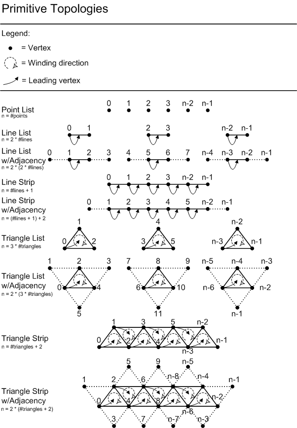
Not shown in the previous diagram (but part of the same list) are 32 additional topologies which represent 1...32 control point patches, respectively. These Patch topologies can be used with Tessellation(11). Also, when Tessellation is disabled(11.8) (meaning no Hull Shader and no Domain Shader bound), they can be fed to the Geometry Shader and/or Stream Output, allowing patch data to be saved to memory, and allowing non-traditional primitive types to be fed to the GS (such as simulating cubes using 8 control point patches to represent 8 vertices).
In Indexed rendering of strip topologies, the maximum representable index value in the index format (i.e. 0xffffffff for 32-bit indices) means the strip defined up to the previous index is to be completed, and the next index is a new strip. This special "cut" value is not required to be used, in which case a DrawIndexed*() command will simply draw one strip. In IndexedInstanced rendering, there is an automatic "cut" after every instance. Regardless of Instanced rendering or not, it is optional whether to make the last index the cut value, or omit the value; both result in the same behavior, except that the IndexCount[PerInstance] parameter to DrawIndexed[Instanced]() is different by 1.
Even if the current Primitive Topology is not a strip, then the cut index value still takes effect, potentially resulting in an incomplete primitive (see next section). Thus, handling of the cut is kept orthogonal to primitive topology, even though it is not useful for some of them.
Note that providing a behavior for the cut value when used with a non-strip topology is a way of saying that the behavior is defined, allowing hardware to keep the cut behavior always enabled. In practice though, using cut for a list topology is obviously not a "feature" that it would ever make sense for an application to author to.
Each Draw*() call starts a new Primitive Topology; there is no persistence of any topology produced by a previous Draw() call. Triangle strips don't continue across Draw() call boundaries.
If a Draw*() call produces incomplete primitives (not enough vertices), either at the end of the Draw*() call, or anywhere in the middle (possible with the "cut" index), any incomplete primitives are silently discarded. For example, suppose a Draw*() call is made with triangle list as the topology, and an vertex count of 5. This case would result in a single triangle, and the last 2 vertices being silently discarded. For another example showing handling of an incomplete primitive, see the diagram under the Geometry Shader Stage here(13.10), depicting which primitives are instantiated given a triangle strip with adjacency that has a dangling vertex.
For the purpose of assigning constant vertex attributes to primitives, there must be a way to map a vertex to a primitive. Let us identify the vertex in a primitive which supplies its per-primitive constant data as the "leading vertex". A primitive topology can have multiple leading vertices, one for each primitive in the topology. The leading vertex for an individual primitive in a topology is the first non-adjacent vertex in the primitive. For the triangle strip with adjacency above, the leading vertices are 0, 2, 4, 6, etc. For the line strip with adjacency, the leading vertices are 1, 2, 3 etc.
Note that adjacent primitives have no leading vertex. This means that there is no primitive data associated with adjacent primitives. With the strip topologies, a given interior primitive has some adjacent primitives which are also interior to the topology, and so actually can have primitive data. However, as far as the Geometry Shader is concerned (it sees a single primitive and its neigboring primitives in an invocation), only the single interior primitive defining the Geometry Shader invocation can have Primitive Data, and adjacent primitives, whether they are interior to the strip or adjacent primitives on the strip, never come with Primitive Data.
The only place in the Pipeline where adjacency information is visible to the application is in the Geometry Shader. Each invocation of the Geometry Shader sees a single primitive: a point, line, or triangle, and some of these might include adjacent vertices.
The inputs to the Geometry Shader are like a single primitive of any of the "list" primitive topologies (with or without adjacency) in the diagram above. When adjacency is available, the Geometry Shader will see the appropriate adjacent vertices along with the primitive's vertices. So for example if the Geometry Shader is invoked with a triangle including adjacency (the source could have been a strip with adjacency), this would mean that data for 6 vertices would be available as input in the Geometry Shader: 3 vertices for the triangle, and 3 for the adjacency.
The data layout for adjacent vertices is identical to the standard vertices they accompany. Note that Vertex Shaders are always run on all vertices, including adjacent vertices. Note that adjacent vertices are typically also surface vertices some other primitive that will get drawn, so the Vertex Shader result cache can take advantage of this.
When the IA is instructed to produce a primitive topology with adjacency for its output, all adjacent vertices must be specified. There is no concept of handling edges with no adjacent primitive. The application must deal with this on their own, perhaps by providing a dummy vertex (possibly forming a degenerate triangle), or perhaps by flagging in one of the vertex attributes whether the vertex "exists" or not. The application's Geometry Shader code will have to detect this situation, if desired, and deal with it manually. Implied in this is that there must be no culling of degenerate primitives until rasterizer setup, so that the Geometry Shader is guaranteed to see all geometry.
Note that when Tessellation is enabled, topologies with adjacency cannot be used. The Tessellator operates a patch at a time without hardware knowledge about adjacency (although shader code is free to encode it on its own). The Tessellator's outputs are independent primitives, with no adjacency information.
VertexID is a 32-bit unsigned integer scalar counter value coming out of Draw*() calls identifying to Shaders each vertex. This value can be declared(22.3.11) for input by the Vertex Shader only.
For Draw() and DrawInstanced(), VertexID starts at 0, and it increments for every vertex. Across instances in DrawInstanced(), the count resets back to the start value. Should the 32-bit VertexID calculation overflow, it simply wraps.
For DrawIndexed() and DrawIndexedInstanced(), VertexID represents the index value.
The mere presence of VertexID in a Vertex Shaders' input declarations activates the feature (there is no other control outside the shader). If the application wishes to pass this data to later Pipeline stages, the application can do so by simply writing the value to a Shader output register like any other data.
For Primitive Topologies with adjacency, such as a triangle strip w/adjacency, the "adjacent" vertices participate have a VertexID associated with them just like the "non-adjacent" vertices do, all generated uniformly (i.e. without regards to which vertices are adjacent and which are not in the topology).
For more information, see the general discussion of System Generated Values here(4.4.4), the reference for VertexID here(23.1), and the System Interpreted/Generated Value input(22.3.11) declaration for Shaders.
PrimitiveID is a 32-bit unsigned integer scalar counter value coming out of Draw*() calls identifying to Shaders each primitive. This value can be declared(22.3.11) for input by either the Hull Shader, Domain Shader, Geometry Shader or Pixel Shader Stage. For the GS and PS, if the GS is active the hardware PrimitiveID goes there and shader computed PrimitiveIDs go to the PS.
PrimitiveID starts at 0 for the first primitive generated by a Draw*() call, and increments for each subsequent primitive. When Draw*Instanced() is used, the PrimitiveID resets to its starting value whenever a new instance begins in the set of instances produced by the call. Should the 32-bit PrimitiveID calculation overflow, it simply wraps.
The mere presence of PrimitiveID in a compatible Shader Stage's input declarations activates the feature (there is no other control outside the shader). In the Geometry Shader this is declared as the special register vPrim (to decouple the value from the other per-vertex inputs). If the application wishes to pass PrimitiveID to a later Pipeline stage, the application can do so by simply writing the value to a Shader output register like any other data. The Pixel Shader does not have a separate input for PrimitiveID; it just goes into a component of a normal input register, with the requirement that the interpolation mode on the entire input register (which may contain other data as well in other components, is chosen as "constant".
For Primitive Topologies(8.10) with adjacency, such as a triangle strip w/adjacency, the PrimitiveID is only maintained for the interior primitives in the topology (the non-adjacent primitives), just like the set of primitives in a triangle strip without adjacency. No point in the Pipeline has a way of asking for an auto-generated PrimitiveID for adjacent primitives.
For more information, see the general discussion of System Generated Values here(4.4.4), the reference for PrimitiveID here(23.2), and the System Interpreted/Generated Value input(22.3.11) and output(22.3.33) declarations for Shaders.
InstanceID is a 32-bit unsigned integer scalar counter value coming out of Draw*() calls identifying to Shaders which instance is being drawn. This value can be declared(22.3.11) for input by the by the Vertex Shader only.
InstanceID starts at 0 for the first instance of vertices generated by a Draw*() call. If the Draw is a Draw*Instanced() call, after each instance of vertices, the InstanceID increments by one. If the Draw is not a Draw*Instanced() call, then InstanceID never changes. Should the 32-bit InstanceID calculation overflow, it simply wraps.
The mere presence of InstanceID in the Vertex Shader's input declarations activates the feature (there is no other control outside the shader). If the application wishes to pass this data to later Pipeline stages, the application can do so by simply writing the value to a Shader output register like any other data.
For more information, see the general discussion of System Generated Values here(4.4.4), the reference for InstanceID here(23.3), and the System Interpreted/Generated Value input(22.3.11) declaration for Shaders.
Section Contents
(back to chapter)
8.19.1 Input Assembler Arithmetic Precision
8.19.2 Addressing Bounds
8.19.3 Buffer and Structure Offsets and Strides
8.19.4 Reusing Input Resources
8.19.5 Fetching Data in the IA vs. Fetching Later (i.e. Multiple Ways to Do the Same Thing)
The Input Assembler performs 32-bit unsigned integer arithmetic, conforming to the IA addressing pseudocode shown in this spec. In other words, should any calculation overflow 32-bits, it would wrap - and should that result happen to fall back into a valid range for the scenario, so be it. Wherever input parameters are listed as signed integers (such as BaseVertexLocation in DrawIndexed()(8.5)) they are interpreted, unaltered, as unsigned 32-bit numbers, used in unsigned 32-bit addressing arithmetic, producing unsigned 32-bit results.
An individual Draw*() call is limited to producing a finite number of vertices. This limit includes any instancing that is occurring within the Draw*() call. Independent of such a limit, there are also limits on how big various source data buffers can be. All of these (large) numbers can be found within the table(21) in the Limits On Various System Resource section. These numbers are expected to be reasonable for the foreseeable lifetime of D3D11.3.
Any calculated address that would fall out of bounds for a Buffer being accessed results in out-of-bounds behavior being invoked, where the return is 0 in all non-missing components of the format (defined in the Input Layout), and the default for missing components (see Defaults for Missing Components(19.1.3.3)). This out-of-bounds behavior applies, for example, when an index refers to a vertex number that is outside of the bound vertex buffer.
The minimum extent for the bounds is any initial offset applied on the Buffer (so "negative" indexing isn't a feature).
See the Element Alignment(4.4.6) section.
It is perfectly legal to read any given memory Buffer in multiple places in the Pipeline, including the IA, simultaneously, even applying different interpretations to the data in the Buffer. A single Buffer can even be set as input at multiple slots at a single stage such as the IA.
For example, suppose an application has a Vertex Shader that requires 2 different sets of input texture coordinates. One scenario could be to use 2 different input Buffers to provide the different texture coordinates to be fetched by the IA (or both texture coordinates could be interleaved in one Buffer). But an alternate, equally valid scenario is to reuse the same source data to supply both texture coordinates to what the Vertex Shader expects as two different sets. This is simply a matter of binding the same input Buffer to two different input slots.
Another way to achieve the same effect of reusing a single set of data is to bind the source texture coordinate Buffer to a single slot and provide a data declaration where the definition of 2 different texture coordinates overlaps (same structure offset). Partial-overlapping of types in a data declaration is even permitted (even though it isn't interesting); the point is that D3D11.3 doesn't care or bother to check.
Similarly, the structure stride in a vertex declaration can be any non-negative value (up to a maximum of 2048 Bytes, and conforming to alignment(4.4.6) rules), without regards to whether it is large enough to support the fields defined for the structure. Again, the point is that D3D11.3 doesn't care or bother to check. Debug tools can be provided to optionally enforce well-ordered, logical data layouts, however the arithmetic that underlying hardware uses to actually address data simply blindly follows the intent shown by the pseudocode for address-calculations for the Draw*()(8.2) routines.
It is legal to have a single Buffer containing both vertex data and index data, and thus bind the Buffer at both a Vertex Buffer input slot and as an Index Buffer simultaneously. One might store indices at the beginning of the Buffer and the vertex data being referred to elsewhere in the same Buffer. D3D11.3 doesn't care.
As yet another, final (contrived) example, to drive the point home: Suppose a Vertex Buffer is set as input to the IA to provide data for vertices going to the Vertex Shader (as usual). Simultaneously, the same Vertex Buffer may be accessed directly by the Vertex Shader, if for some reason the Shader occasionally wanted to look at some of the input data for vertices other than itself.
The highly flexible and programmable nature of the D3D11.3 Pipeline leads to many situations where there are multiple ways to accomplish a single task. A particular example relevant to this section is that the fetching of vertex data performed by the IA can be identically performed by doing memory fetches from the Vertex Shader only given a VertexID as input. There are nice properties from this, such as the fact that even though the amount of data the IA can pre-fetch for a single vertex is limited in size, memory fetches from shaders can allow much more unbounded amounts of vertex data to be fetched if necessary. Memory fetches from shaders can also use much more complex addressing arithmetic than the common-case dedicated fixed-function arithmetic used by the IA.
No guarantees or requirements are made by D3D11.3, however, as to the performance characteristics of using alternative mechanisms to perform a task that can be performed by an explicit feature intended for that task in the Pipeline. As a general rule, whenever there is an explicit mechanism to perform a task in D3D11.3, IHVs and ISVs should assume that as much as possible, the dedicated functionality is the preferred route, at least when all of or most of the other parts of the graphics Pipeline are simultaneously active.
When the Input Assembler reads Elements of data from Buffers, it gets converted to the appropriate 32-bit data type for the Format(19.1) interpretation specified. The conversion uses the the Data Conversion(3.2) rules. If the source data contains 32-bit per-component float, UINT or SINT data, it is read without modifying the bits at all (no conversion).
If a Vertex Buffer or Index Buffer is read by the Input Assembler, but the slot being read has no Buffer bound, the result of the read is 0 for all expected components. Even though there is format information available via the input layout, defaults are not applied to missing channels for this case.
The following example shows DrawIndexedInstanced()(8.6) being used to draw 3 instances of an indexed mesh.
The example does not attempt to draw anything particularly interesting, but it does show most of the functionality of the IA being used at once, in complete detail. Included is a depiction of the resulting workload for the rest of the Graphics Pipeline.
As input, one Vertex Buffer supplies Vertex Data, another Vertex Buffer supplies Instance Data, and there is an Index Buffer. The data layouts and configuration of all of these buffers is illustrated. VertexID(8.16), PrimitiveID(8.17) and InstanceID(8.18) are all shown as well, assuming Shaders in the pipeline requested them. The Primitive Topology(8.10) being rendered is triangle strip with adjacency. The Index Buffer has a Cut(8.12) in it, so multiple strips are produced (per instance).
Various states shown in boxes represent the API settings for Buffers and for the IA states described earlier in this IA spec.
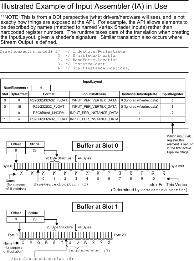
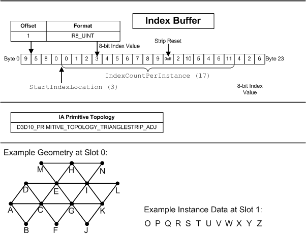
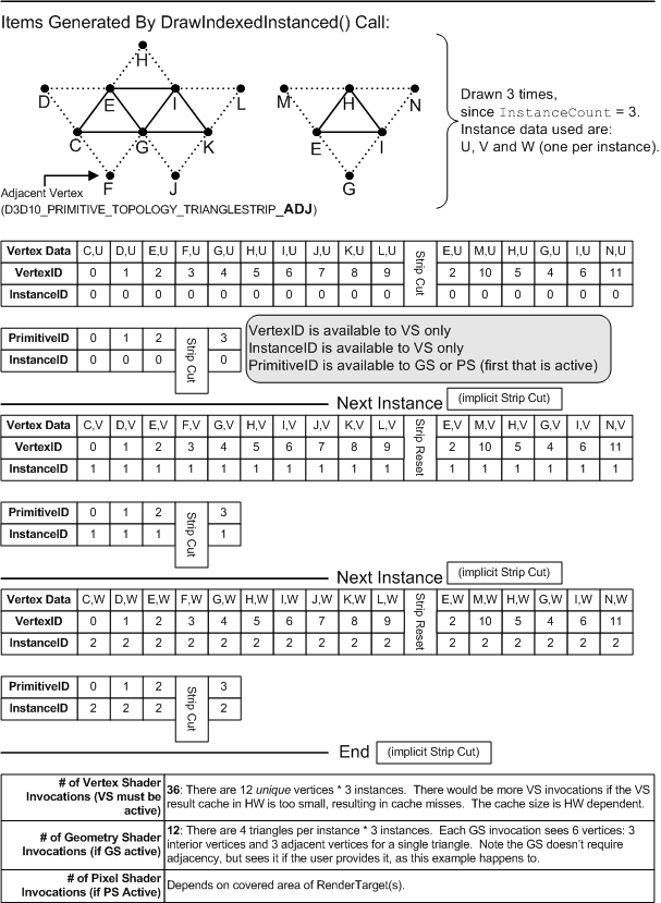
Chapter Contents
(back to top)
9.1 Vertex Shader Instruction Set
9.2 Vertex Shader Invocation
9.3 Vertex Shader Inputs
9.4 Vertex Shader Output
9.5 Registers
Summary of Changes in this Chapter from D3D10 to D3D11.3
Back to all D3D10 to D3D11.3 changes.(25.2)
The Vertex Shader instruction set is listed here(22.1.3).
For every vertex generated by the IA, Vertex Shader is invoked, provided that there is a miss on the hardware's Vertex Shader result cache. Adjacent vertices are treated equivalently to interior vertices in a topology, so the Vertex Shader is executed for all vertices.
The primary inputs to a Vertex Shader invocation are 32 32-bit*4-component registers (v#) comprising the elements of the input vertex (not all have to be used). ConstantBuffers (cb#) and textures (t#) provide random access input to Vertex Shaders.
The output of a Vertex Shader is up to 32 32-bit*4 component registers (o#). The o# registers to be written by the Shader must be declared (i.e. "dcl_output o[3].xyz").
The following registers are available in the vs_5_0 model:
| Register Type | Count | r/w | Dimension | Indexable by r# | Defaults | Requires DCL |
|---|---|---|---|---|---|---|
| 32-bit Temp (r#) | 4096 (r# + x#[n]) | r/w | 4 | n | none | y |
| 32-bit Indexable Temp Array (x#[n]) | 4096 (r# + x#[n]) | r/w | 4 | y | none | y |
| 32-bit Input (v#) | 32 | r | 4 | y | none | y |
| Element in an input resource (t#) | 128 | r | 1 | n | none | y |
| Sampler (s#) | 16 | r | 1 | n | none | y |
| ConstantBuffer reference (cb#[index]) | 15 | r | 4 | y(contents) | none | y |
| Immediate ConstantBuffer reference (icb[index]) | 1 | r | 4 | y(contents) | none | y |
| Output Registers: | ||||||
| NULL (discard result, useful for ops with multiple results) | n/a | w | n/a | n/a | n/a | n |
| 32-bit output Vertex Data Element (o#) | 32 | w | 4 | n/a | n/a | y |
| Unordered Access View (u#) | 64 | r/w | 1 | n | n | y |
Chapter Contents
(back to top)
10.1 Hull Shader Instruction Set
10.2 Hull Shader Invocation
10.3 HS State Declarations
10.4 HS Control Point Phase
10.5 HS Patch Constant Phases
10.6 Hull Shader Structure Summary
10.7 Hull Shader Control Point Phase Contents
10.8 Hull Shader Fork Phase Contents
10.9 Hull Shader Join Phase Contents
10.10 Hull Shader Tessellation Factor Output
10.11 Restrictions on Patch Constant Data
10.12 Shader IL "Ret" Instruction Behavior in Hull Shader
10.13 Hull Shader MaxTessFactor Declaration
Summary of Changes in this Chapter from D3D10 to D3D11.3
Back to all D3D10 to D3D11.3 changes.(25.2)
For a Tessellation overview, see the Tessellator(11) section.
The Hull Shader instruction set is listed here(22.1.4).
The Hull Shader operates once per patch, transforming Control Points, computing Patch Constant data and defining Tessellation Factors.
The Hull Shader has four phases, all defined together as one program. That is, from the API/DDI point of view, the Hull Shader is a single atomic shader, and its phases are an implementation detail within the Hull Shader program. Implementations can choose to exploit independent work within a Patch by executing work within a single patch in parallel.
The phases appear in the Intermediate Language as standalone shaders, each with individual input and output declarations tailored to what each independent program is doing. However the inputs and outputs across all of the shaders come out of a fixed pool of Hull Shader-wide input data and output storage, described later in great detail.
The Hull Shader phase structure is depicted in the following picture:
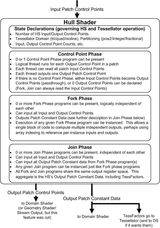
This section of the Hull Shader has no executable code. It simply declares some overall characteristics of Hull Shader operation, such as how many control points the HS inputs and outputs (an independent number). The operation of the fixed function Tessellator is also defined here – such as choosing the patch domain, partitioning etc. A tessellation pattern overview is given here(11.7).
Note that declarations that are typical in shaders, such as input and output register declarations and declarations of input Resources, Constant Buffers, Samplers etc. are part of each individual shader phase below, not part of this HS State declaration section.
See Tessellator State(11.7.15).
In the Hull Shader’s Control Point phase, a thread is invoked once per patch output control point. An input value vOutputControlPointID(23.7) identifies to each thread which output control point it represents. Each of the threads see shared input of all the input control points for the patch. The output of each thread is one of the output control points for the patch.
Section Contents
(back to chapter)
10.5.1 Overview
10.5.2 HS Patch Constant Fork Phase
10.5.3 HS Patch Constant Join Phase
The Patch Constant phases compute constant data such as Tessellation Factors(10.10) (how much the fixed function Tessellator should tessellate), as well as any other Patch Constant data, beyond the patch Control Points, that the application may need in the Domain Shader(12) (the shader that runs once per Tessellator output point).
The Patch Constant phases occur after the Control Point phase is complete, and has read-only access to all of the input and output Control Points. So for example, Control Points could be examined to help calculate Tessellation Factors(10.10) for each patch edge.
There are two Patch Constant phases:
The Patch Constant Fork Phase is a collection of an arbitrary number of independent programs. For the discussion in this section let us call these independent programs mini-shaders.
Each mini-shader produces independent (non-overlapping) parts of the total output Patch Constant data (such as all the different TessFactors(10.10)).
An implementation could choose to execute each mini-shader in parallel, since they are independent. Or, in the opposite extreme an implementation could choose to trivially concatenate all the mini-shaders together and run them serially. Such transformations of the mini-shaders are trivial to perform (in a driver’s compiler) given they all share the same inputs and perform non-overlapping writes to a unified output space.
An implementation could even choose to hoist any amount of the code from the Fork Phase phase up into the Control Point Phase if that happened to be most efficient. This is allowable because all the parts of a Hull Shader are specified together as if it is one program – how its contents are executed does not matter as long as the output is deterministic.
The shared inputs to each mini-shader are all of the Control Point Phase’s Input and Output Control Points.
The output of each mini-shader is a non overlapping subset of the output Patch Constant Data.
There is no communication of data between mini-shaders, other than the fact that they share Control Point input.
To further enable parallelism within a single mini-shader, any mini-shader can be declared to run in an instanced fashion, given a fixed instance count per patch. During execution, each instance of an instance mini-shader is identified by a ForkInstanceID(23.8) and is responsible for producing a unique output, typically by indexing an array of outputs. So for example, a single mini-shader instanced 4 times could output edge TessFactors for each edge of a quad patch.
The final Hull Shader phase is the Patch Constant Join Phase. This phase behaves the same way as the Fork Phase, in that there can be multiple Join programs that are independent of each other. All of them execute after all the Fork Phase programs. An example use for this phase is to derive TessFactors(10.10) for the inside of a patch given the edge TessFactors computed in the previous phase.
The input to each Patch Constant Join Phase shader are all the Control Point Phase’s Input and Output Control Points as well as all the Patch Constant Fork Phase’s output.
The output of each Patch Constant Join Phase shaders is a subset of the output Patch Constant data that does not overlap any of the outputs of the shaders from the Patch Constant Fork Phase or other Join Phase shaders.
Similar to the fork phase, to enable parallelism within a join phase mini-shader, any mini-shader can be declared to run in an instanced fashion, given a fixed instance count per patch. During execution, each instance of an instance mini-shader is identified by a JoinInstanceID(23.9) and is responsible for producing a unique output, typically by indexing an array of outputs. So for example, a single mini-shader instanced 2 times could output inside TessFactors for each inside direction of a quad patch.
The various phases of the Hull Shader are described in the Intermediate Language as separate shader models. A single Hull Shader program consists of a collection of the following shaders appearing in the order listed here:
hs_decls(22.3.14): Hull Shader State Declarations
hs_control_point_phase(22.3.21): Hull Shader Control Point Phase
hs_fork_phase(22.3.23): Hull Shader Patch Constant Fork Phase
hs_join_phase(22.3.26): Hull Shader Patch Constant Join Phase
From the point of view of the HLSL code author and API user, the name for the Hull Shader compiler target is simply hs_5_0
hs_control_point_phase(22.3.21) is a shader program with the following register model. Note the footnotes which provide a detailed discussion of output storage size calculations.
| Register Type | Count | r/w | Dimension | Indexable by r# | Defaults | Requires DCL |
|---|---|---|---|---|---|---|
| 32-bit Temp (r#) | 4096 (r# + x#[n]) | r/w | 4 | N | None | Y |
| 32-bit indexable Temp Array (x#[n]) | 4096 (r# + x#[n]) | r/w | 4 | Y | None | Y |
| 32-bit Input (v[vertex][element]) | 32(element)*32(vert) | r | 4 | Y | None | Y |
| 32-bit UINT Input vOutputControlPointID(23.7) | 1 | r | 1 | N | None | Y |
| 32-bit UINT Input PrimitiveID (vPrim) | 1 | r | 1 | N | n/a | Y |
| Element in an input resource (t#) | 128 | r | 128 | Y | None | Y |
| Sampler (s#) | 16 | r | 1 | Y | None | Y |
| ConstantBuffer reference (cb#[index]) | 15 | r | 4 | Y | None | Y |
| Immediate ConstantBuffer reference (icb[index]) | 1 | r | 4 | Y(contents) | None | Y |
| Output Registers: | ||||||
| 32-bit output Vertex Data Element (o#) | 32, see (1) below | w | 4 | Y | None | Y |
(1) Each Hull Shader Control Point Phase output register is up to a 4-vector, of which up to 32 registers can be declared. There are also from 1 to 32 output control points declared, which scales amount of storage required. Let us refer to the maximum allowable aggregate number of scalars across all Hull Shader Control Point Phase output as #cp_output_max.
#cp_output_max = 3968 scalars
This limit happens to be based on a design point for certain hardware of 4096*32-bit storage here. The amount for Control Point output is 3968=4096-128, which is 32(control points)*4(component)*32(elements) - 4(component)*32(elements). The subtraction reserves 128 scalars (one control point) worth of space dedicated to the HS Phase 2 and 3, discussed below. The choice of reserving 128 scalars for Patch Constants (as opposed to allowing the amount to be simply whatever of the 4096 scalars of storage is unused by output Control Points) accommodates the limits of another particular hardware design. Note the Control Point Phase can declare 32 output control points, but they just can’t be fully 32 elements with 4 components each, since the total storage would be too high.
InstanceID(8.18) and VertexID(8.16) can be input as long as the previous Vertex Shader stage outputs them.
PrimitiveID(8.17) is also available as a scalar 32-bit integer input for each Control Point. PrimitiveID indicates the current patch in the Draw*() call, starting with 0. This PrimitiveID is the same value that the Geometry Shader would see for every patch if it input PrimitiveID - that is every point/line/triangle produced by the tessellator for a given patch has a single PrimitiveID for the entire Patch.
OutputControlPointID(23.7) is a scalar 32-bit integer input for each Control Point identifying which one it is [0..n-1] given n declared output Control Points.
Section Contents
(back to chapter)
10.8.1 HS Fork Phase Programs
10.8.2 HS Fork Phase Registers
10.8.3 HS Fork Phase Declarations
10.8.4 Instancing of an HS Fork Phase Program
10.8.5 System Generated Values in the HS Fork Phase
There can be 0 or more Fork Phase programs present in a Hull Shader. Each of them declares its own inputs, but they come from the same pool of input data – the Control Points. Each Fork Phase program declares its own outputs as well, but out of the same output register space as all Fork Phase and Join Phase programs, and the outputs can never overlap.
The following registers are visible in the hs_fork_phase(22.3.23) model.
The input resources (t#), samplers (s#), constant buffers (cb#) and immediate constant buffer (icb) below are all shared state with all other HS Phases. That is, from the API/DDI point of view, the Hull Shader has a single set of input resource state for all phases. This goes with the fact that from the API/DDI point of view, the Hull Shader is a single atomic shader; the phases within it are implementation details.
Note the footnotes which provide a detailed discussion of output storage size calculations.
| Register Type | Count | r/w | Dimension | Indexable by r# | Defaults | Requires DCL |
|---|---|---|---|---|---|---|
| 32-bit Temp (r#) | 4096 (r# + x#[n]) | r/w | 4 | N | None | Y |
| 32-bit indexable Temp Array (x#[n]) | 4096 (r# + x#[n]) | r/w | 4 | Y | None | Y |
| 32-bit Input Control Points (vicp[vertex][element]) (pre-Control Point Phase) | 32, see (1) below | r | 4(component)*32(element)*32(vert) | Y | None | Y |
| 32-bit Output Control Points (vocp[vertex][element]) (post-Control Point Phase) | 32, see (1) below | r | 4(component)*32(element)*32(vert) | Y | None | Y |
| 32-bit UINT Input PrimitiveID (vPrim) | 1 | r | 1 | N | n/a | Y |
| 32-bit UINT Input ForkInstanceID(23.8) (vForkInstanceID) | 1 | r | 1 | N | n/a | Y |
| Element in an input resource (t#) | 128 | r | 128 | Y | None | Y |
| Sampler (s#) | 16 | r | 1 | Y | None | Y |
| ConstantBuffer reference (cb#[index]) | 15 | r | 4 | Y | None | Y |
| Immediate ConstantBuffer reference (icb[index]) | 1 | r | 4 | Y(contents) | None | Y |
| Output Registers: | ||||||
| 32-bit output Patch Constant Data Element (o#) | 32, see (2) below | w | 4 | Y | None | Y |
(1) The HS Fork Phase’s Input Control Point register (vicp) declarations must be any subset, along the [element] axis, of the HS Control Point input (pre-Control Point phase). Similarly the declarations for inputting the Output Control Points (vocp) must be any subset, along the [element] axis, of the HS Output Control Points (post-Control Point Phase).
Along the [vertex] axis, the number of control points to be read for each of the vicp and vocp must similarly be a subset of the HS Input Control Point count and HS Output Control Point count, respectively. For example, if the vertex axis of the vocp registers are declared with n vertices, that makes the Control Point Phase’s Output Control Points [0..n-1] available as read only input to the Fork Phase.
(2) The HS Fork and Join phase outputs are a shared set of 4 4-vector registers. The outputs of each Fork/Join phase program cannot overlap with each other. System Interpreted values such as TessFactors(10.10) come out of this space.
The declarations for inputs, outputs, temp registers, resource etc. in an HS Fork Phase program are like any standalone shader. A given HS Fork Phase program need only declare what it needs to read and write. Further, if it does not need to see all Input or Output Control Points, it can declare a subset of the counts for each, by declaring a smaller number on the [vertex] array axis than the corresponding number of Control Points actually available.
There is not a way to declare that a sparse set of the Control Points is read. E.g. a shader that needs read Input Control Points [0],[3], [11] and [15] would just declare the Input Control Point (vicp) register’s [vertex] axis size as 16. Note that if references to the Control Points from shader code use static indexing, it will be obvious to drivers exactly what subset of Control Points is actually needed by the program anyway.
Any individual HS Fork Phase program can be declared to execute instanced, with a declaration identifying a fixed instance count from 1 to 128 (128 is the maximum number of scalar Patch Constant outputs). The HS Fork Phase program executes the declared number of times per patch, with each instance identified by its 32-bit UINT input register vForkInstanceID(23.8).
Note that if the role of an instanced Fork Phase program is for each instance to produce a System Interpreted Value(4.4.5), say one of the edge TessFactors(10.10) for a quad patch per instance, the declarations for each of those outputs would identify the System Interpreted Value being produced, just like any other shader.
The HS Fork Phase can input PrimitiveID(8.17) in its own register just like the HS Control Point Phase. The value in this register is the same as what the HS Control Point Phase sees. The other special input register in the HS Fork Phase is vForkInstanceID(23.8), described previously.
The system doesn’t go out of its way to automatically provide other System Generated Values(4.4.4) (VertexID(8.16), InstanceID(8.18)) to the HS Fork Phase. Values like these are part of the Input Control Points (if they were declared to be there) already, so the HS Fork phase can read VertexID/InstanceID by reading them out of the Input Control Points.
The treatment of InstanceID(8.18) does seem strange, in that InstanceID would be the same for all Control Points in a Patch (indeed, unchanging across multiple patches), yet it shows up per-Input Control Point. However, this is consistent with the behavior elsewhere in the pipeline, where the first active stage that can input a System Generated Value (for InstanceID, that is the Vertex Shader) is responsible for passing the value down to the next stage via shader output (rather than the hardware feeding the value down to subsequent stages separately). For the Geometry Shader to see InstanceID, it also shows up in each input vertex there, just like it shows up in each Input Control Point in the Hull Shader.
Section Contents
(back to chapter)
10.9.1 HS Join Phase Program
10.9.2 HS Join Phase Registers
10.9.3 HS Join Phase Declarations
10.9.4 Instancing of an HS Join Phase Program
10.9.5 System Generated Values in the HS Join Phase
There can be 0 or more Join Phase programs present in a Hull Shader. Each of them declares its own inputs, but they come from the same pool of input data – the Control Points as well as the Patch Constant outputs of the Fork Phase programs. Each Join Phase program declares its own outputs as well, but out of the same output register space as all Fork Phase and Join Phase programs, and the outputs can never overlap.
The following registers are visible in the hs_join_phase(22.3.26) model. Note there are three sets of input registers: vicp (Control Point Phase Input Control Points), vocp (Control Point Phase Output Control Points), and vpc (Patch Constants). vpc are the aggregate output of all the HS Fork Phase programs(s). The HS Join Phase output o# registers are in the same register space as the HS Fork Phase outputs.
The input resources (t#), samplers (s#), constant buffers (cb#) and immediate constant buffer (icb) below are all shared state with all other HS Phases. That is, from the API/DDI point of view, the Hull Shader has a single set of input resource state for all phases. This goes with the fact that from the API/DDI point of view, the Hull Shader is a single atomic shader; the phases within it are implementation details.
Note the footnotes which provide a detailed discussion of output storage size calculations.
| Register Type | Count | r/w | Dimension | Indexable by r# | Defaults | Requires DCL |
|---|---|---|---|---|---|---|
| 32-bit Temp (r#) | 4096 (r# + x#[n]) | r/w | 4 | N | None | Y |
| 32-bit indexable Temp Array (x#[n]) | 4096 (r# + x#[n]) | r/w | 4 | Y | None | Y |
| 32-bit Input Control Points (vicp[vertex][element]) (pre-Control Point Phase) | 32, see (1) below | r | 4(component)*32(element)*32(vert) | Y | None | Y |
| 32-bit Output Control Points (vocp[vertex][element]) (post-Control Point Phase) | 32, see (1) below | r | 4(component)*32(element)*32(vert) | Y | None | Y |
| 32-bit Input (vpc[element]) (Patch Constant Data) | 32, see (3) below | r | 4 | Y | None | Y |
| 32-bit UINT Input PrimitiveID (vPrim) | 1 | r | 1 | N | n/a | Y |
| 32-bit UINT Input JoinInstanceID(23.9) (vJoinInstanceID) | 1 | r | 1 | N | n/a | Y |
| Element in an input resource (t#) | 128 | r | 128 | Y | None | Y |
| Sampler (s#) | 16 | r | 1 | Y | None | Y |
| ConstantBuffer reference (cb#[index]) | 15 | r | 4 | Y | None | Y |
| Immediate ConstantBuffer reference (icb[index]) | 1 | r | 4 | Y(contents) | None | Y |
| Output Registers: | ||||||
| 32-bit output Patch Constant Data Element (o#) | 32, see (2) below | w | 4 | Y | None | Y |
(1) The HS Join Phase’s Input Control Point register (vicp) declarations must be any subset, along the [element] axis, of the HS Control Point input (pre-Control Point phase). Similarly the declarations for inputting the Output Control Points (vocp) must be any subset, along the [element] axis, of the HS Output Control Points (post-Control Point Phase).
Along the [vertex] axis, the number of control points to be read for each of the vicp and vocp must similarly be a subset of the HS Input Control Point count and HS Output Control Point count, respectively. For example, if the vertex axis of the vocp registers are declared with n vertices, that makes the Control Point Phase’s Output Control Points [0..n-1] available as read only input to the Join Phase.
(2) The HS Fork and Join phase outputs are a shared set of 4 4-vector registers. The outputs of each Fork/Join phase program cannot overlap with each other. System Interpreted values such as TessFactors(10.10) come out of this space.
(3) In addition to Control Point input, the HS Join phase also sees as input the Patch Constant data computed by the HS Fork Phase program(s). This shows up at the HS Fork phase as the vpc# registers. The HS Join Phase’s input vpc# registers share the same register space as the HS Fork Phase output o# registers. The declarations of the o# registers must not overlap with any HS Fork phase program o# output declaration; the HS Join Phase is adding to the aggregate Patch Constant data output for the Hull Shader.
The declarations for inputs, outputs, temp registers, resource etc. in an HS Join Phase program function the same was as HS Fork Phase declarations(10.8.3).
Any individual HS Join Phase program can be declared to execute instanced, with a declaration identifying a fixed instance count from 1 to 128 (128 is the maximum number of scalar Patch Constant outputs). The HS Join Phase program executes the declared number of times per patch, with each instance identified by its 32-bit UINT input register vJoinInstanceID(23.9).
Note that if the role of an instanced Join Phase program is for each instance to produce a System Interpreted Value(4.4.5), say one of the inside TessFactors(10.10) for a quad patch per instance, the declarations for each of those outputs would identify the System Interpreted Value being produced, just like any other shader.
System Generated Values are dealt with the same(10.8.5) way in the HS Join Phase as the HS Fork Phase. Instead of vForkInstanceID(23.8), in the Join Phase the same thing is called vJoinInstanceID(23.9). PrimitiveID(8.17) is available a standalone input register.
Section Contents
(back to chapter)
10.10.1 Overview
10.10.2 Tri Patch TessFactors
10.10.3 Quad Patch TessFactors
10.10.4 Isoline TessFactors
Hull Shader(10) Fork and Join Phase code can declare up to 6 of their output scalars as System Interpreted Values that identify various Tessellation Factors, driving how much tessellation the fixed function Tessellator should perform. For example, on a Quad there are 4 TessFactors for the edges, as well as 2 for the inside. HLSL exposes alternative (helper) ways to generate the inside tessfactors automatically from the edge TessFactors, e.g. deriving them by min/max/avg on the edge values, and possibly scaling based on user-provided scale values. The hardware does not understand anything about this helper processing (it just appears as shader code)
The optional (from the HLSL author point of view) tessellation factor processing results in HLSL compiler autogenerated shader code in either or both of the Fork and Join Phases. This standard processing can involve cleaning up of values, handling of special low TessFactor cases to prevent popping, and rounding of the values depending on the tessellation mode.
The final Tessellation Factors after this processing go to the fixed function Tessellator hardware – TessFactors for each edge and explicit TessFactors for the patch inside (as opposed to TessFactorScale the user specifies).
Downstream, Domain Shader(12) code may be interested in seeing all of the intermediate values generated during any optional TessFactor processing. For example, to be able to perform blending during Pow2 Partitioning tessellation, one might want to see the ratio between unrounded and rounded TessFactor values. To enable that, the auto-generated code in the Fork and/or Join Phases will output not only final TessFactor values for the tessellator, but also the intermediate values, so the Domain Shader can access them. There are at most 12 such additional values (in the case of a Quad Patch). Again, the hardware does not understand anything about these "helper" values, and they are not discussed in detail here.
The next sections describe just the TessFactors relevant to the hardware without discussing the various optional helper routines that HLSL provides to derive them.
Further information about how Tessellation Factors are interpreted is here(11.7.10).
float3 SV_TessFactor(24.8)
The first component provides the TessFactor for the U==0 edge of the patch.
The second component provides the TessFactor for the V==0 edge of the patch.
The third component provides the TessFactor for the W==0 edge of the patch.
The above hardware/system interpreted values must be declared in the same component of 3 consecutive registers (since indexing is on that axis).
float SV_InsideTessFactor(24.9)
This determines how much to tessellate the inside of the tri patch.
float4 SV_TessFactor(24.8)
The first component provides the TessFactor for the U==0 edge of the patch.
The second component provides the TessFactor for the V==0 edge of the patch.
The third component provides the TessFactor for the U==1 edge of the patch.
The fourth component provides the TessFactor for the V==1 edge of the patch.
The ordering of the edges is clockwise, starting from the U==0 edge (visualized as the "left" edge of the patch).
The above hardware/system interpreted values must be declared in the same component of 4 consecutive registers (since indexing is on that axis).
float2 SV_InsideTessFactor(24.9)
The first component determines how much to tessellate along the U direction of the inside of the patch.
The second component determines how much to tessellate along the V direction of the inside of the patch.
float2 SV_TessFactor(24.8)
The first component destermines the line density (how many tessellated parallel lines to generate in the V direction over the patch area).
The second component determines the line detail (how finely tessellated each of the parallel lines is, in the U direction over the patch area).
The above hardware/system interpreted values must be declared in the same component of 2 consecutive registers (since indexing is on that axis).
IsoLines are discussed further here(11.6)
The Hull Shader output Patch Constant data appears as 32 vec4 elements. The placement of the Final TessFactors are constrained as described in the previous sections – each grouping of TessFactors must appear in a specific order in the same component of consecutive registers/elements in the Patch Constant Data. E.g. For Quad Patches, the four Final Edge TessFactors in a fixed order make up one grouping, and the two Final Inside TessFactors in a fixed order make up another separate grouping.
Shader indexing of the Patch Constant data across the 32 vec4 elements is restricted, due to the limitations of a particular hardware implementation, as follows:
Since the Hull Shader has multiple phases, each of which can be instanced (e.g. multiple Control Points in the Control Point phase, or instanced Fork or Join Phases), the "ret*" (return(22.7.16) or conditional return(22.7.17)) shader instruction is defined to end only the current instance of the current phase. So a "ret*" in the Control Point Phase would only finish the current Control Point invocation without affecting the others or other phases. Or a "ret*" in a Fork or Join Phase program would only end that instance of that program without affecting other instances (if it is instanced) or other Fork/Join programs.
The HS State Declaration Phase can optionally include a fixed float32 MaxTessFactor(22.3.20) in the range {1.0...64.0}.
This MaxTessFactor declaration(22.3.20) is useful when application knows the maximum amount of tessellation it could possibly ask for through the TessFactor values will output from the Hull Shader. Communicating this knowledge to the device allows it to optionally take advantage and perform better scheduling of resources on the GPU.
If a MaxTessFactor is declared, it is enforced by HLSL autogenerated TessFactor clamping code as the last step in the calculation of all of the following hardware System Interpreted Values (whose meanings were described earlier):
SV_TessFactor
SV_InsideTessFactor
For simplicity only a single MaxTessFactor value can be declared, and when it is present, it is applied to all the TessFactors listed above.
The device sees the MaxTessFactor declaration as a part of the Hull Shader. The knowledge of this declaration is what hardware can optionally take advantage of to optimize Tessellation performance for content going through that Hull Shader, versus an otherwise identical Hull Shader without the declaration.
If HLSL fails to enforce the MaxTessFactor when it is declared (by clamping the HS output TessFactors), and a TessFactor larger than MaxTessFactor arrives at the Tessellator, the Tessellator’s behavior is undefined. Hitting this undefined situation is a Microsoft HLSL compiler (or driver compiler) bug, not the fault of the shader author or hardware.
Note that independent of this optional application-defined MaxTessFactor, the Tessellator always performs some additional basic clamping and rounding of Final TessFactors as appropriate for the situation, described later (5.5). Those manipulations guarantee the hardware behavior by limiting the range of inputs possible. The only exception to that well defined hardware interface is this MaxTessFactor declaration which must rely on HLSL to generate code to enforce it. The reason it is the responsibility of HLSL to enforce consistency in this one case is it was too late in the spec process to arrive at any consistent hardware definition here, either by defining what the hardware behavior is if MaxTessFactor was not enforced but then exceeded at runtime, or getting all hardware vendors enforce the same MaxTessFactor clamping in hardware.
Chapter Contents
(back to top)
11.1 Tessellation Introduction
11.2 Tessellation Pipeline
11.3 Input Assembler and Tessellation
11.4 Tesellation Stages
11.5 Fixed Function Tessellator
11.6 IsoLines
11.7 Tessellation Pattern
11.8 Enabling Tessellation
Summary of Changes in this Chapter from D3D10 to D3D11.3
Back to all D3D10 to D3D11.3 changes.(25.2)
The tessellation model processes a patch at a time, either a quad, tri or "isoline" domain, and does not embody any specific surface representation. It strictly generates domain locations that are fed to a programmable shader (Domain Shader(12)) that is responsible for generating positions and any ancillary shading information (texture coordinates, tangent frames, normals, etc.). The domain locations are water tight across a boundary if identical level of detail is used, otherwise the hardware plays no role in ensuring crack free surfaces. This specification does not cover any specific surface representation, or how to map representations to the given pipeline.
Requirements
See the D3D pipeline(2) diagram to see how Tessellation (Hull Shader(10), Tessellator(11) and Domain Shader(12)) fits in.
The Input Assembler(8) has a new primitive topology called "patch list", which is accompanied by a vertex count per patch: [1..32]. This is also described under Patch Topologies(8.11).
All existing IA behaviors work orthogonally with patches. i.e. indexing, instancing, DrawAuto etc.
Incomplete patches are discarded – for example if the vertex count is 32 per patch, and a Draw call specifies 63 vertices, one 32 vertex patch will be produced, and the remaining 31 vertices will be discarded.
Here are pointers to the stages involved in Tessellation, in the order of data flow:
Fixed Function Tessellator(11.5) (this chapter, below)
This fixed function stage takes floating point TessFactor values as input and generates a tessellation of the domain. The domain can be tri, quad or isoLine (see next section for a definition of isoLines).
The tessellator generates a couple of things:
Note the domains are defined such that for isoLines and quads, the V direction is clockwise from the U direction. For tri domain, UVW are clockwise, in that order.
Adjacency(8.15) information is not available when using the tessellator - only independent points, lines or triangles are generated. The order that points/lines/triangles and their vertices are produced must be invariant between similar tessellator invocations on the same device, but no explicit order is prescribed.
The isoLine domain is a specialized form of the quad domain. It is the only domain that can produce tessellated lines. For isoLines, the U direction over a quad domain is the direction tessellated lines are drawn (lines of constant V). There are two TessFactor(10.10.4) values:
The first is the line density, which is always rounded to integer and determines how many U-parallel tessellated line segments to generate across the V direction. The spacing of these line segments across V is uniform, starting at V=0. So if the line density is 1, a single tessellated line is generated from (U=0,V=0) to (U=1,V=0). If the line density is 2, the first tessellated line is generated from (0,0) to (1,0) and the second tessellated line is generated from (0,0.5)-(1,0.5). Notice that no line is ever generated at V=1.
The second TessFactor is the line detail, determining how much to tessellate each line of constant V.
For more concrete info on the tessellation pattern for isolnes see IsoLine Pattern Details(11.7.8).
Section Contents
(back to chapter)
11.7.1 Overview
11.7.2 Tessellation Pattern Overview
11.7.3 Fractional Partitioning
Details of the point placement and connectivity described in words in this section.
A more concrete description can be found in the reference fixed function tessellator code, entirely encapsulated in the following C++ files:
The inside of a triangle/quad patch is a tessellated triangle/square based on a specified InsideTessFactor(s). For a triangle, there is a single TessFactor(10.10.2) for the inside region of the patch. For a quadrilateral, there are 2 inside TessFactors(10.10.3).
HLSL exposes helpers that can optionally derive inside TessFactors from the edge TessFactors (these amount to shader code, so the hardware doesn't need to know about them). For example in the case of a quad patch, the helpers have a couple of options for deriving inside TessFactors – 1-axis and 2-axis. In the 1-axis mode, the inside TessFactor reduction is applied on all 4 edges producing a single inside TessFactor. In the 2-axis mode, the reduction from 4 edge TessFactors is divided into two separate parts. The V==0 and V==1 edge TessFactors are reduced to a single TessFactor for the V direction of the interior. Similarly the U==0 and U==1 TessFactors are reduced to a single TessFactor for the U direction on the interior.
The boundaries of the patch transition between the inside TessFactor(s) and each per-edge TessFactor.
There are two basic flavors of fractional tessellation: either using an even number of segments (intervals) on an edge or an odd number. When using an even number of segments the coarsest an edge can be refined is to have two segments an edge, so it is impossible to model a level of detail with a single segment.
For integer partitioning, TessFactors are rounded to integer. The parity (even/odd) of each edge and inside TessFactor after rounding determines how that area is tessellated: an odd integer TessFactor matches odd fractional tessellation at the same TessFactor. Similarly, an even integer TessFactor matches even fractional tessellation at the same TessFactor.
For pow2 partitioning, TessFactors are rounded to a power of 2, and tessellation of pow2 TessFactors matches even fractional tessellation at the same TessFactor, but in addition the power of 2 mode can go down to 1 segment on any side (1 is a power of 2). From the hardware point of view there is no distinction between pow2 and integer - the hardware doesn't do the rounding of the TessFactors to pow2. That rounding is the responsibility of the HLSL compiler, given the shader being authored using the appropriate helper intrinsics in shader code (not discussed here).
Mapping Vertices to Texels 1:1 in an Application
Tri vs Quad Density Comparison
Example: Displacement Mapping
The order that geometry is generated for a patch must be repeatable on a device, however no particular ordering of the geometry within a patch is prescribed. A strict requirement is that all geometry for a given patch flows down the pipeline before any geometry for subsequent patches.
Suppose the rasterizer is the next active stage in the pipeline after tessellation, and there are vertex attributes that are declared in the Pixel Shader with constant interpolation. The leading vertex, used to provide the constant attribute for any individual line or triangle, can be any of the vertices in the line or triangle (albeit repeatable for a given patch and tessellator configuration on a device).
When a patch topology is used, PrimitiveID(8.17) identifies which patch in the Draw*() call is being processed, starting from the Hull Shader onward. Even though tessellation may produce multiple points/lines/triangles, for a given patch, all of the primitives generated for it have the same PrimitiveID. As such, the freedom of point/line/triangle ordering within a patch is not visible to shader code. When a patch topology is used, the true "primitive" is the patch itself.
The TessFactor number space roughly corresponds to how many line segments there are on the corresponding edge. This isn’t a precise definition of the number of segments because different tessellation modes snap to different numbers of segments (i.e. integer versus fractional_even versus fractional_odd).
For integer partitioning, TessFactor range is [1 ... 64] (fractions rounded up).
For pow2 partitioning, TessFactor range is [1,2,4,8,16,32,64]. Anything outside or in between values in this set is rounded to the next entry in the set by HLSL code... so from the hardware point of view, pow2 partitioning technically isn't different from integer partitioning.
For fractional odd partitioning, TessFactor range is [1 ... 63]. Odd TessFactors produce uniform partitioning of the space. Other TessFactors in the range produce a segment count that is the next odd TessFactor higher, transitioning the point locations based on the distance between the nearest lower odd TessFactor and nearest greater odd TessFactor.
For fractional even tessellation, TessFactor range is [2 ... 64]. Even TessFactors produce uniform partitioning of the space. Other TessFactors in the range produce a segment count that is the next even TessFactor higher, transitioning the point locations based on the distance between the nearest lower even TessFactor and nearest greater even TessFactor.
For the IsoLine domain, the line detail TessFactor honors all the above modes. However the line density TessFactor always behaves as integer – [1 ... 64] (fractions rounded to next).
This particular clamp on TessFactors is discussed here(10.13), and is independent of the hardware clamps defined in the rest of this section.
The following describes the float32 patch edge TessFactor range that the hardware Tessellator must accept from the Hull Shader.
First of all, if any edge TessFactor is <= 0 or NaN, the patch is culled.
Otherwise, hardware must clamp each edge input TessFactor to the range specified below.
| Partitioning | Min Edge TessFactor | Max Edge TessFactor | Comments |
|---|---|---|---|
| Even_Fractional | 2 | 64 | |
| Odd_Fractional | 1 | 63 | |
| Integer (Pow2 maps to integer in hardware) | 1 | 64 | After clamping, round result to next integer. |
For IsoLines, the LineDensity Tessfactor (which is how many constant V iso-lines to draw) is clamped by the hardware to [1...64] and rounded to the next integer.
In addition to patch edge TessFactors, hardware will be given inside TessFactors from the Hull Shader. There are two inside TessFactors for quad patches (U and V axes), and one inside TessFactor for tri patches.
These HS outputs may have been derived (optinally) from the edge TessFactors via some operation such as max or avg in Hull Shader code autogenerated by HLSL. This derivation may involve low TessFactor fixups to prevent popping as TessFactors transition through extreme cases. Such processing is just shader code, irrellevant to the hardware.
For the final inside TessFactors coming out of the Hull Shader, the following is pseudocode for the hardware validation hardware must do, effectively creating safe bounds on the complexity of cases the hardware tessellation algorithm has to handle.
    // Compute HWInsideTessFactorU/V for quad patch (similar tri patch case has only one axis),
    // given HSOutputInsideTessFactorU/V + 4 edge TessFactors.
    // This is just the fixed function hardware processing, independent of shader pre-conditioning
    // of the TessFactors (which the hardware does not need to know about).
    float lowerBound, upperBound;
    switch(partitioning)
    {
        case integer:
        case pow2: // don’t care about pow2 distinction for validation, just treat as integer
            lowerBound = 1;
            upperBound = 64;
            break;

        case even_fractional:
            lowerBound = 2;
            upperBound = 64;
            break;

        case odd_fractional:
    #define EPSILON 0.0000152587890625 // 2^(-16), min positive fixed point fraction
            if( any TessFactor, edge or inside is greater than (1.0 + EPSILON/2) )
            {
                // If any Tessfactor will be > 1 after rounding during
                // the float to fixed point conversion that happens later
                // then make all inside TessFactors > 1.
                lowerBound = 1.0 + EPSILON;
            }
            else // all are <= 1.0f or NaN
            {
                lowerBound = 1;
            }
            upperBound = 63;
            break;
    }

    HWInsideTessFactorU = min( upperBound, max( lowerBound, HSOutputInsideTessFactorU ) );
    HWInsideTessFactorV = min( upperBound, max( lowerBound, HSOutputInsideTessFactorV ) );
    // A tri patch only has one insideTessFactor instead of U/V
    // Note the above clamps map NaN to lowerBound based on D3D/IEEE754R min/max rules

    if( integer or pow2 partitioning )
    {
         round HWInsideTessFactorU to next integer (don’t care about pow2 distinction for validation)
         round HWInsideTessFactorV to next integer
         // tri patch only has one insideTessFactor instead of U/V
    }

    // After this, all TessFactors are converted to .16 fixed point using D3D float->fixed
    // conversion rules(3.2.4.1) (incl round-to-nearest-even).  Topology and domain coordinate placement
    // is done based on the fixed point TessFactors.
If any of the edge TessFactors from the HS for a patch are <= 0 or NaN, the patch is culled. No Domain Shader invocations or anything later in the pipeline are produced for that patch.
A discussion elsewhere about enabling and disabling(11.8) of tessellation discusses how patch culling interacts with tessellation disabled, but patches being streamed out to memory.
A shared edge has to generate identical domain locations for crack free tessellation to be possible. Domain Shader authors are responsible for achieving this, given some guarantees from the hardware. First, hardware tessellation on any given edge must always produce a distribution of domain points symmetric about the edge based on the TessFactor for that edge alone. Second, the parameterization of each domain point (U/V for quad or U/V/W for tri) must produce “clean” values in the space [0.0 ... 1.0]. “Clean” means that given a domain point on one side of the edge, with the parameter for that edge (say it is U) in [0 ... 0.5], the mirrored domain point produced on the other side, call it U' in [0.5 ... 1.0] will have a complement satisfying (1-U') == U exactly.
Even if a neighboring patch sharing an edge happens to produce a complementary parameterization (U moving in the other direction, and/or U/V swapped), both side’s parameterization for each shared edge domain point will be equivalent because they are clean.
Having clean parameterization means that DS authors can write domain point evaluation algorithms with a carefully constructed order of operations that is guaranteed to produce the same result even if the control points for the patch are traversed in reverse order and/or with the parameter space complemented.
Tessellator input float32 TessFactor values are immediately converted to fixed point. Note this is after float processing of TessFactors, such as Inside TessFactor derivation has been done by HLSL generated shader code in HS Patch Constant Fork or Join Phases. Once the final TessFactors have been converted to fixed point, all remaining tessellator arithmetic (computing domain locations), is performed using fixed point arithmetic with 16 bits of fraction. The last step in domain point coordinate calculation is to convert the coordinates back to float32 for input to the Domain Shader.
The fact that output U/V/W domain coordinates(23.10) have been quantized to 16 bit fixed point means there is a uniform spacing of representable values across the [0...1] range. This uniform spacing facilitates the symmetry and watertightness issues discussed above.
Due to the fixed point arithmetic involved, it is possible for the tessellator to produce degenerate lines or triangles, where each vertex has identical domain coordinates. This will not be visible if the primitives are sent to the rasterizer, because they will be culled. However, if the Geometry Shader and/or Stream Output are enabled, the degenerate primitives will appear, and it is the application’s responsibility to be robust to this. For example, Geometry Shader code could check for and discard degenerates if that turns out to be the only way to avoid the algorithm being used from falling over on the degenerate input.
If the Tessellator’s output primitive is points (as opposed to triangles or lines), this scenario requires only unique points within a patch to be generated. The one exception is points that are on the threshold of merging, if TessFactors were to incrementally decrease, may appear in the system as duplicated points (with the same U/V coords) in an implementation dependent way.
What does 16-bit fixed point math for the domain coordinate generation mean?
Suppose a single patch is drawn 64 meters wide.
There is enough precision to place points at 2 mm resolution.
Section Contents
(back to chapter)
11.8.1 Final D3D11 Definition for Enabling Tessellation
The presence of both a Hull Shader and Domain Shader enables tessellation. When a Hull Shader and Domain Shader are bound, the Input Assembler topology is required to be a patch type (otherwise behavior is undefined). If a Hull Shader is bound and no Domain Shader is bound, or vice versa, the behavior is undefined.
Patches can be used at the Input Assembler without tessellation (no Hull Shader or Domain Shader), as long as the Geometry Shader and/or Stream Output are being used.
When tessellation is disabled (no Hull Shader and no Domain Shader bound), patches arriving at the Geometry Shader cause the GS to be invoked once per patch. Each GS invocation sees all the Control Points of the patch as an array of input vertices.
Allowing the GS to be invoked with patches allows it to effectively input non-traditional topologies (beyond points, lines, triangles). E.g. to invoke the GS with a cube as its input primitive, one could send 8 Control Point patches.
The GS does not support output of patches. The output of the GS remains one of: point list, line strips or triangle strips.
Sending un-tessellated patches to NULL GS + Stream Output is valid. This enables, for example, Control Points that have gone through the Vertex Shader to be streamed out for multi-pass or reuse scenarios. Note, however, it is not possible for Hull Shader outputs to be streamed out (or go into the GS) - the presence of the Hull Shader requires a simultaneous Domain Shader and enables Tessellation – both of which consumes Hull Shader output entirely.
When un-tessellated patches arrive at Stream Output, each Control Point in the patch appears as a single vertex for Stream Output. This definition is similar to the way NULL GS + Stream Output behaves with traditional primitive topologies such as triangle lists. As with other primitive types, only complete patches get written out; if there is not enough room to store a complete patch, it is discarded.
It could have been defined that Control Points arriving at the rasterizer are interpreted as points and rasterized as such, but that would have required a RenderTarget-space projected "position" to be present in the control points, and the application would have to have wanted to draw them as points. This is an extremely unlikely scenario, not worth targeting. Therefore, if an un-Tessellated patch arrives at the Rasterizer, behavior is undefined and the debug runtime will call this out as an error.
Original Definition for Enabling Tessellation
The behaviors described so far in this section are the result of making cutbacks from the originally defined behavior. The cutbacks were made due to concerns over how the design was unfriendly to certain choices of D3D11 hardware implementations, resulting in among other issues unreasonable hardware and driver complexity.
The original behavior is documented below for the sake of history,formatted like this. It is a superset of the final behavior above, so a lot of the content appears the same. Briefly, the most interesting extra bit of functionality was being able to pass Hull Shader outputs to GS/StreamOutput without tessellation. Tessellation was enabled only by the presence of a Domain Shader (which then required a Hull Shader). Without a Domain Shader, tessellation was disabled, but he Hull Shader could still be present, outputting control points downstream.
Enabling Tessellation (this crossed out text is no longer representative of D3D11)
The presence of a Domain Shader enables tessellation. When a Domain Shader is bound, the Input Assembler topology is required to be a patch type, and a Hull Shader must also be bound, otherwise the behavior is undefined (debug error).
The absence of a Domain Shader disables tessellation. The Input Assembler topology is still allowed to be a patch type when tessellation is disabled. The following subsections describe what this means.
Sending Un-Tessellated Patches to the Geometry Shader
When tessellation is disabled, patches arriving at the Geometry Shader (with or without a Hull Shader Present) cause the GS to be invoked once per patch. Each GS invocation sees all the Control Points of the patch as an array of input vertices. Patch Constant data from the Hull Shader, such as Tessellation Factors, are not visible to the GS.
Allowing the GS to be invoked with patches allows it to effectively input non-traditional topologies (beyond points, lines, triangles). E.g. to invoke the GS with a cube as its input primitive, one could send 8 Control Point patches.
Sending Un-Tessellated Patches to Null GS + Stream Output
Sending Un-Tessellated Patches to NULL GS + Stream Output is valid. This enables, for example, Control Points that have gone through the Vertex Shader and/or Hull Shader to be streamed out for multi-pass or reuse scenarios.
Each Control Point in the patch appears as a single vertex for Stream Output. This definition is similar to the way NULL GS + Stream Output behaves with traditional primitive topologies such as triangle lists. As with other primitive types, only complete patches get written out; if there is not enough room to store a complete patch, it is discarded.
If the HS is active, that means the HS output Control Points can be streamed out. Without the HS active, the VS output for each Control Point in a patch can be streamed out.
Patch Constant data output by the Hull Shader, such as Tessellation Factors, are not available to Stream Output. As a workaround, an application that needs to stream out Patch Constant data could set up the tessellator to run, but then have the Domain Shader flag for discarding (such as assigning a bad vertex position) all but the first n domain points for the patch. The n domain points (where n is chosen to fit all the Patch Constant data across n vertices’ storage) would save out all the patch data from the Domain Shader. The GS/Stream Output could then send the data to memory as a sequence of individual points.
If the HS culls a patch (by specifying an edge Tessellation factor <= 0) when tessellation is disabled, the "cull" has no effect on Stream Output of the patch. This choice was made because it is deemed not worth defining that the Stream Output stage must be able to interpret some Patch Constant data (TessFactors) to make a decision about what to stream out. Thus if un-tessellated patches are being sent to Stream Output, there is no way to cull them.
Sending Un-Tessellated Patches to the Rasterizer
It could have been defined that control points arriving at the rasterizer are interpreted as points and rasterized as such, but that would have required a RenderTarget-space projected "position" to be present in the control points, and the application would have to have wanted to draw them as points. This is an extremely unlikely scenario, not worth targeting. Therefore, if an un-Tessellated patch arrives at the Rasterizer, behavior is undefined and the debug runtime will call this out as an error.
Summary of Changes in this Chapter from D3D10 to D3D11.3
Back to all D3D10 to D3D11.3 changes.(25.2)
For a Tessellation overview, see the Tessellator(11) section.
The Domain Shader instruction set is listed here(22.1.5).
Inputs for this stage are the 2D or 3D domain location(23.10) generated by the tessellator(11) and all of the data generated by the Hull Shader(10). This latter data is visible to all domain points in a patch. In all other ways this shader is effectively analogous to a Vertex Shader(9).
The Domain Shader can see all the data output by both phases of the Hull Shader, as well as the domain location of a particular point. The Domain Shader is invoked for every domain location generated by the Tessellator.
The following registers are available in the ds_5_0 model.
| Register Type | Count | r/w | Dimension | Indexable by r# | Defaults | Requires DCL |
|---|---|---|---|---|---|---|
| 32-bit Temp (r#) | 4096 (r# + x#[n]) | r/w | 4 | N | None | Y |
| 32-bit indexable Temp Array (x#[n]) | 4096 (r# + x#[n]) | r/w | 4 | Y | None | Y |
| 32-bit Input Control Points (vcp[vertex][element]) | 32, see (1) below | r | 4(component)*32(element)*32(vert) | Y | None | Y |
| 32-bit Input Patch Constants (vpc[vertex]) | 32, see (1) below | r | 4 | Y | None | Y |
| 32-bit input location in domain (vDomain(23.10).xy, vDomain(23.10).xyz)) | 1 | r | 3 | N | n/a | Y |
| 32-bit UINT Input PrimitiveID (vPrim) | 1 | r | 1 | N | n/a | Y |
| Element in an input resource (t#) | 128 | r | 128 | Y | None | Y |
| Sampler (s#) | 16 | r | 1 | Y | None | Y |
| ConstantBuffer reference (cb#[index]) | 15 | r | 4 | Y | None | Y |
| Immediate ConstantBuffer reference (icb[index]) | 1 | r | 4 | Y(contents) | None | Y |
| Output Registers: | ||||||
| 32-bit output Vertex Data Element (o#) | 32 | w | 4 | Y | None | Y |
(1) The domain shader sees the Hull Shader outputs in 2 separate sets of registers. The vcp registers can see all of the Hull Shader’s output Control Points. The vpc registers can see all of the Hull Shader’s Patch Constant output data.
Since code for Hull Shader Patch Constant Fork or Join Phases output TessFactors using names such as SV_TessFactor, the DS must match those declarations on the equivalent vpc input if it wishes to see those values.
InstanceID(8.18) and VertexID(8.16) can be input as long as the Hull Shader output these values (per-Control Point).
The domain location is another System Generated Value, appearing in its own input register (vDomain(23.10)).
The final set of System Values are the various TessFactors produced by the Hull Shader, discussed elsewhere(10.10). These can be declared as input out of part of the input Patch Constant (vpc) registers.
Chapter Contents
(back to top)
13.1 Geometry Shader Instruction Set
13.2 Geometry Shader Invocation and Inputs
13.3 Geometry Shader Output
13.4 Geometry Shader Output Data
13.5 Geometry Shader Output Streams
13.6 Geometry Shader Output Limitations
13.7 Partially Completed Primitives
13.8 Maintaining Order of Operations Geometry Shader Code
13.9 Registers
13.10 Geometry Shader Input Register Layout
Summary of Changes in this Chapter from D3D10 to D3D11.3
Back to all D3D10 to D3D11.3 changes.(25.2)
The Geometry Shader instruction set is listed here(22.1.6).
When a Geometry Shader is active, it is invoked once for every primitive passed down or generated earlier in the Pipeline. Each invocation of the Geometry Shader sees as input the data for the invoking primitive, whether that is a single point, a single line, a single triangle, or the Control Points for a Patch (if a Patch arrives with Tessellation disabled). A triangle strip from earlier in the Pipeline would result in an invocation of the Geometry Shader for each individual triangle in the strip (as if the strip were expanded out into a triangle list). All the input data for each vertex in the individual primitive is available (i.e. 3 verts for triangle), plus adjacent vertex data if applicable/available. All vertex inputs/Element-layout/adjacency to be read must be declared, and this declaration must be compatible with the data being produced above in the Pipeline. Other inputs include textures, and also Primitive ID as a 32-bit scalar integer input .
An alternate method of invoking the Geometry Shader is via instancing. A GS Instancing declaration(22.3.7) specifies a (fixed) number of times for the GS to be invoked for each primitive. Each instance that executes is identified by a GS instance ID value [0...n-1], and the outputs of each GS instance are appended to the end of the outputs of the previous invocation (with an implicit cut of the topology between instances - see the description of cutting further below). The maximum instance count that can be declared is 32, but for a full explanation of constraints of GS instancing, see the description of the GS instancing declaration(22.3.7)
Some background: The D3D10 Geometry Shader had a limit on the amount of vertex data that a single shader invocation can emit. The limit is 1024 scalars of data (fatter vertices means fewer vertices can be emitted). The shader program must statically declare the maximum amount of vertices it intends to output. It was desirable to relax this limit in some fashion.
Another limitations of the D3D10 Geometry Shader design was the GS emits vertices is implicitly serial. e.g. if a GS program that wants to project an input triangle onto 6 cube faces, it must project to each cube face and emit geometry for each face one at a time. It was desirable to have a way a GS program could be authored to explicitly reveal to the hardware when the calculations to produce different batches of geometry form the same GS program are independent of each other. This way, hardware can execute each batch of vertex generation in parallel.
The GSInvocations Pipeline Statistics counter(20.4.7) reports the number of primitives input to the GS multiplied by the instance count per primitive. That is, each "instance" counts as a GSInvocation.
The Geometry Shader outputs data one vertex at a time using the "emit"(22.8.3) command. The topology of these vertices is determined by a fixed declaration(22.3.8), choosing one of: pointlist, linestrip, or trianglestrip as the output for the GS. Strips can be restarted by using the "cut"(22.8.1) command, which ends the current strip at the last emitted vertex, so that the next emitted vertex begins a new strip. The "emitThenCut"(22.8.5) instruction both emits a vertex, and stops the current strip on this vertex, so that the next vertex that is emitted begins a new strip. For pointlist output, "cut" has no effect (including the "cut" part of "emitThenCut").
The outputs of a given invocation of the Geometry Shader are independent of other invocations (though ordering(4.2) is respected). A Geometry Shader emitting triangle strips will start a new strip on every invocation. In addition, as mentioned above, an invocation of the Geometry Shader can produce multiple separate strips using "cut"s.
The Geometry Shader must declare the maximum number of vertices an invocation of the Shader will output. The total amount of data that a Geometry Shader invocation can produce is 1024 32-bit values. The calculation of the Stream Output record with one or more streams is as follows: Given that each stream declares its outputs in its own clean slate view of the full output register set, the total output record size is the number of scalars in the union of all the stream declarations. This size multiplied by the max output vertex count must not exceed 1024. When Geometry Shader instancing is used, the Stream Output record size restriction applies to each instance individually
With only a single output stream, the above rule matches D3D10.
The limit on Geometry Shader output is based on how many "emit" calls the Shader makes. The limit on Geometry Shader output is not affected in any way by the size of the output buffer(s) that are present or whether or not they have even been bound. Even if no output Buffers happen to be bound to a Stream and a vertex is output (and therefore dropped), it still counts against the limit.
Hardware must enforce the limit above by stopping writes if the Geometry Shader program continues after emitting the declared maximum number of vertices.
See the documentation of the GS maximum output vertex count declaration(22.3.5), as well as the GS Instancing declaration(22.3.7) for more details.
The o# registers to be written by the Geometry Shader must be declared (e.g. "dcl_output o[3].xyz"). The set of these declarations defines which registers are read when an "emit"(22.8.3) command is issued, defining a vertex. Therefore, all vertices emitted by the Geometry Shader have the same data layout.
When a Geometry Shader output is identified as a System Interpreted Value(4.4.5) (e.g. "renderTargetArrayIndex" or "position"), hardware looks at this data and performs some behavior dependent on the value, in addition to being able to pass the data itself to the next Shader stage for input. When such data output from the Geometry Shader has meaning to the hardware on a per-primitive basis (such as "renderTargetArrayIndex" or "ViewportArrayIndex"), rather than on a per-vertex basis (such as "clipDistance" or "position"), the per-primitive data is taken from the Leading Vertex(8.14) emitted for the primitive.
Each time an "emit"(22.8.3) or "emitThenCut"(22.8.5) is issued the contents of the declared Geometry Shader output registers are read to produce a vertex, and in addition the Geometry Shader outputs immediately become uninitialized. In other words, if any output data needs to be repeated for consecutive vertices, the Geometry Shader program must write the data over again to the output registers for each vertex.
The Geometry Shader outputs have a close relationship to the Stream Output Stage/functionality, described here(14.3).
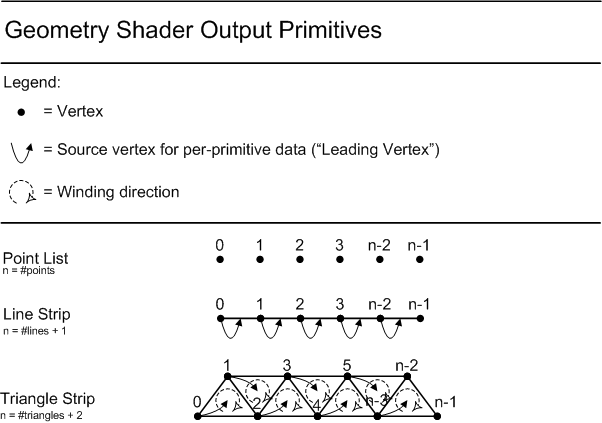
STREAM: For the discussion here, let us define a stream as a sequence of writes of a structure of data out of a shader. A Geometry Shader can output up to 4 streams, each at different rates, with independent data going to each stream. The utility of this is in conjunction with Stream Output(14).
BUFFER: For the discussion in this section, in the context of Stream Output(14), a Buffer is a resource in memory that can receive any subset of the data from one stream. A stream can have its data split out (not replicated) across multiple buffers, and this mapping is defined by a Stream Output declaration (which is not visible in the Geometry Shader code). A Buffer cannot receive data from multiple streams at once.
4 streams can be declared(22.3.9) by the GS. Without the GS present, all vertex data is a single stream.
When the GS defines multiple streams, variants of the "emit"(22.8.3), cut(22.8.1) or "emitThenCut"(22.8.5) instructions which take an immediate stream # [0..4-1] parameter must be used by the GS to indicate which stream is being output. These instructions are "emit_stream"(22.8.4), cut_stream(22.8.2) and "emitThenCut_stream"(22.8.6), respectively.
From the point of view of the Geometry Shader, all the declarations of its output registers appear multiple times indepdendently, once per stream. A statement appears in the bytecode setting the current output stream being declared, and subsequent declarations of output registers define what data gets latched when vertex data is emitted to each stream. The set of output registers available to the GS program during execution is the union of all output registers declared for each stream (individual streams can use the same output registers). When a vertex is emitted to a given stream, only the output registers declared for that stream feed the output to the stream, however ALL declared output registers for all streams become uninitialized.
If output register indexing is declared(22.3.30), specifying a range of output registers that can be dynamically indexed, the register space that can be declared for indexing is the union of all stream output register declarations.
When outputting to multiple streams, the GS output topology declaration(22.3.8) must appear for each stream, and must bet set to "point". In other words, multiple streams means that non-point output is unavaliable.
The points-only limitation with multi-stream output was a hardware limitation during the design. Perhaps in future DX releases this can be relaxed - that is to allow arbitrary topologies in each stream. An example would be to output triangles to one stream that goes to the rasterizer, while sending points to another stream that goes to Stream Output at a different frequency for compiling a list of coordinates to revisit with some postprocessing later. Or to render some triangles while saving off rejected ones.
When outputting to only a single stream, the output from the GS can be a point list, line strip or triangle strip (strips are expanded to lists when streamed to memory), or a patch list. Output of a patch list from the GS is only valid for Stream Output, not for rasterization (undefined behavior).
When outputting to multiple streams, one of them can be sent to the rasterizer (independently of whether it is also streaming to memory). The Stream Output declaration specifies this (outside the shader code, but appearing to the driver side by side). Interpolation modes, System Interpreted Values and System Generated Values can be declared on any combination of Streams in the Shader, but the only ones that have any meaning are the ones corresponding to the Stream (if any) declared (outside the shader) as going to the rasterizer (if any). For Streams that are not going to the Rasterizer, the names are ignored. Notice that the same shader could be created with different Stream Output declarations, each time selecting a different Stream to go to Rasterization.
If a GS with streams is passed to CreateGeometryShader at the API/DDI (meaning there is no Stream Output declaration or rasterizer stream selection), the active stream defaults to 0. So stream 0 goes to rasterization if rasterization is enabled, and the absence of a Stream Output declaration means nothing is streamed out to memory. If the stream selected to go to rasterization isn’t declared in the GS or doesn’t include a position and rasterization is enabled, behavior is undefined, just as with any shader that feeds the rasterizer without a position.
Sending one of the streams to rasterization with multiple streams isn't a particularly interesting feature for now, since in the multi-stream case all streams are point lists.
Interpolation modes declared for the outputs on one Stream don’t have to match those on another Stream. Note that when the Geometry Shader is created, a choice of which stream (if any) is going to rasterization is made, so the driver shader compiler only needs to pay attention to interpolation modes and System Interpreted Values (such as "position") only on at most a single Stream’s declarations
When the application knows that some GS outputs will be treated as per-primitive constant at the subsequent Pixel Shader, the Geometry Shader need only initialize such output registers when they represent the Leading Vertex(8.14) for a primitive. For example, on the last 2 vertices in a triangle strip, outputs that (on Leading vertices) would have be treated as constant by the Pixel Shader need not be written. If Stream Output is being used, which has no knowledge of what data is per-primitive constant or not, in the expansion of GS output strips to lists, Stream Output simply dumps out all the declared outputs for each vertex for each primitive. If the GS chooses to not write out what it knows is non-Leading-Vertex data for Elements that will be used to drive per-primitive constants in a later pass, uninitialized data gets written to these unwritten Elements in Stream Output. This is fine as long as the application never attempts to later read such uninitialized Stream Output data. If the application later recirculates the Streamed Out data in a way that correctly interprets only per-primitive constant data at Leading Vertices and never interprets the uninitialized data at non-Leading-Vertices (even though it does get read back into the pipeline), no undefined behavior results.
There is a mechanism to retrieve the number of output primitives in the output buffer. Further details regarding writing to memory from the Geometry Shader are described elsewhere in the spec.(14)
Partially completed primitives could be generated by the the Geometry Shader if the Geometry Shader ends and the primitive is incomplete. Incomplete primitives are silently discarded and no counters are incremented. This is similar to the way the IA treats Partially Completed Primitives(8.13).
To ensure consistent order of operations on an edge and primitive level for primitives that show up in multiple invocations of the Geometry Shader (as an adjacent primitive in some invocations, or the root primitive for one invocation), it is up to the application to write Shader code that traverses vertices in a consistent manner. This ordering can be obtained by a variety of methods, including simply sorting of vertices based on position in Shader code. A more robust ordering can be achieved by providing a vertex "coloring" (a number) as vertex attribute, such that for any primitive, the coloring is guaranteed to be unique for each vertex in the primitive. This method has the benefit that the sorting operation in the Geometry Shader is more efficient (and robust) than sorting xyz vertex positions. Colorings can be generated offline by an authoring tool.
The following registers are available in the gs_5_0 model:
| Register Type | Count | r/w | Dimension | Indexable by r# | Defaults | Requires DCL |
|---|---|---|---|---|---|---|
| 32-bit Temp (r#) | 4096 (r# + x#[n]) | r/w | 4 | n | none | y |
| 32-bit Indexable Temp Array (x#[n]) | 4096 (r# + x#[n]) | r/w | 4 | y | none | y |
| 32-bit Input (v[vertex][element]) | 32 | r | 4(comp)*32(vert) | y | none | y |
| 32-bit Input Primitive ID (vPrim) | 1 | r | 1 | n | none | y |
| 32-bit Input Instance ID (vInstanceID) | 1 | r | 1 | n | none | y |
| Element in an input resource (t#) | 128 | r | 1 | n | none | y |
| Sampler (s#) | 16 | r | 1 | n | none | y |
| ConstantBuffer reference (cb#[index]) | 15 | r | 4 | y(contents) | none | y |
| Immediate ConstantBuffer reference (icb[index]) | 1 | r | 4 | y(contents) | none | y |
| Output Registers: | ||||||
| NULL (discard result, useful for ops with multiple results) | n/a | w | n/a | n/a | n/a | n |
| 32-bit output Vertex Data Element (o#) | 32 | w | n/a | n/a | 4 | y |
The Geometry Shader must declare which type of primitive it expects as input, out of the set of choices: {point,line,triangle,line_adj,triangle_adj,1-32 control point patch list}. The input primitive type specifies the number of vertices that are present, and the vertices are always fully indexed (there is no declaration for vertex indexing range). Even if strips are being used earlier in the Pipeline, individual primitives cause Geometry Shader Invocations. See the GS Input Primitive Declaration Statement(22.3.6) in the instruction reference.
The following diagrams depict the layout of Geometry Shader Input Primitives into the input v# registers:
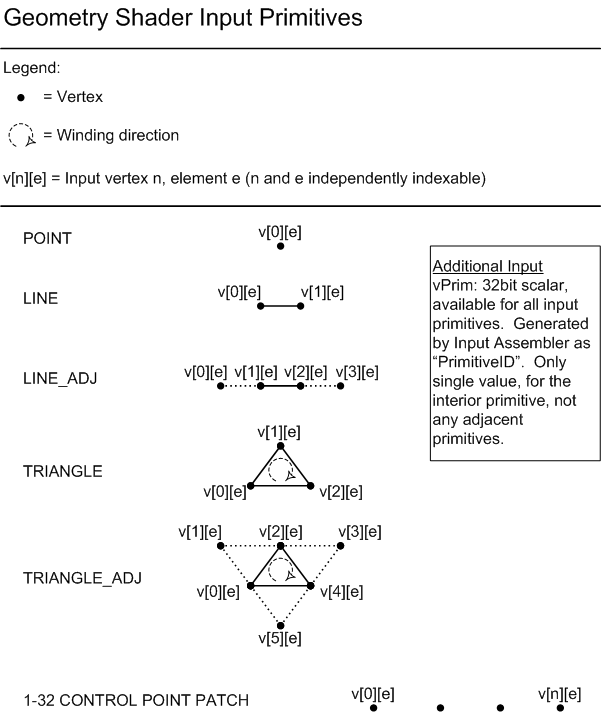
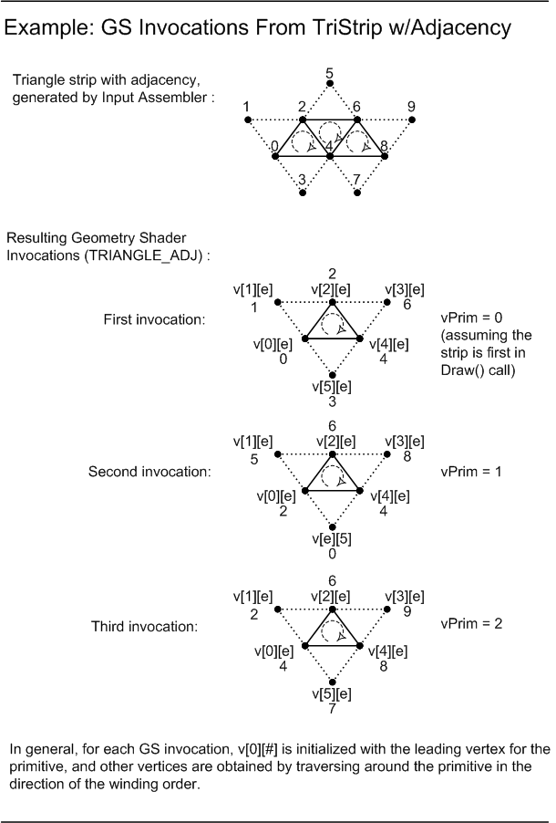
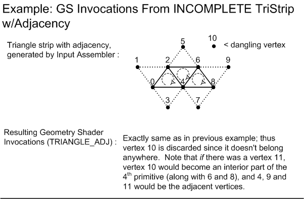
Chapter Contents
(back to top)
14.1 Mapping Streams to Buffers
14.2 Stream Output Buffer Declarations/Bindings
14.3 Stream Output Declaration Details
14.4 Current Stream Output Location
14.5 Tracking Amount of Data Streamed Out
14.6 Stream Output Buffer Bind Rules
14.7 Stream Output Is Orthogonal to Rasterization
Summary of Changes in this Chapter from D3D10 to D3D11.3
Back to all D3D10 to D3D11.3 changes.(25.2)
The Pipeline can stream vertices out to memory just before clipping and rasterization (even if rasterization is still enabled). Vertices are always written out as complete primitives (e.g. 3 vertices at a time for triangles); incomplete primitives are never written out.
Just before Streaming Out, all topologies are always expanded to lists (i.e. if the topology is a triangle strip, it is expanded to a triangle list, having 3 vertices per primitive).
If the Geometry Shader is active, it is capable of producing outputs with up to 32 Elements per-vertex (each Element up to 4 components) for the Rasterizer, any subset of which can be routed to Stream Output. The presence of the GS allows multiple streams to be generated as well, as described here(13.5).
If the Geometry Shader is not active, whatever data arrives at the point in the pipeline where Stream Output appears (just before clipping and rasterization) can be Streamed Out (after expansion to a list topology as described above). Topologies with adjacency discard the "adjacent" vertices and only Stream Out the "interior" vertices. Patch topologies arriving at Stream Output can only go to Stream Output; the rasterizer must be disabled (undefined behavior otherwise).
In the expansion of strips to lists of primitives on Stream Output from the Geometry Shader, there is no notion of any data being able to be treated as "constant"; for each Geometry Shader output primitive (after expansion from a strip to a list), the vertices each originate from separate "emit"(22.8.3) instructions. Applications can still take advantage of this behavior to store primitive data, simply by relying on the fact that if streamed out geometry is recirculated back into the Pipeline in another pass, the Rasterizer will treat the Leading Vertex(8.14) in each primitive as the source for attributes that are declared as constant by the Pixel Shader.
A description of the distinction between a Stream and Buffer is given here(13.5). Up to 4 Streams can be present when the GS is used, otherwise there is a single Stream, Stream 0.
Stream Output can send data from any Stream to up to 4 Buffers simultaneously. The total number of output Buffers across all Streams is also constrained to 4. Data from multiple Streams cannot go to a single Buffer, but each Stream can send its output to multiple Buffers. Stream data cannot be replicated across multiple buffers.
Up to 128 scalar components of data per-vertex can be streamed out across the output Buffers, as long as the total window of data being output per-vertex to any one Buffer is 512 bytes or less. Vertex stride to a given Buffer can be up to 2048 bytes.
The mapping of data from Streams to where they are written in output Buffers appears in a declaration outlined further below.
In all cases, the only supported output data formats at Stream Output are 32-bit per component integer and floating point formats, with 1 to 4 components. This is not as general as the other Resource input/output paths in the D3D11.3 Pipeline. See the "Stream Output" column in the formats(19.1) table to see which formats can be used for Stream Output (all of which can of course be used at other parts of the D3D11.3 Pipeline for input). When any given 32-bit component of data in the Pipeline goes out the Stream Output path and gets written to memory, the hardware must simply dump out the 32 bits (per component) of data out unaltered, which is consistent with the sorts of formats supported for Stream Output described here.
The selection of which Elements to send to the Stream Output is tied to the Geometry Shader. When a Geometry Shader program is "Created" on the D3D11.3 Device, additional parameters can be passed into the "Create" call alongside the Geometry Shader code, describing both (a) what subset of data from the GS output to send to Stream Output for each of 1 to 4 Streams, (b) where to write the data to memory, (c) selection of 0 or 1 of the output Streams as going to the Rasterizer (indepdendent of it is going to Stream Output as well). If the Geometry Shader is not needed, but Stream Output functionality is desired, a "NULL" GS program can be specified, along with a Stream Output declaration for Stream 0 only, in which case whatever geometry reaches the GS stage of the pipeline gets Streamed out
The vertices in one Stream reaching the point in the pipeline just before the Rasterizer/clipping can be sent both to the Rasterizer (if the Pixel Shader is active) as well as to Stream Output if it is active, simultaneously. The Pixel Shader can consume any subset of the data reaching it, while Stream Output can simultaneously select any other (possibly overlapping) subset of the data.
The "NULL" GS + Stream Output scenario enables operations such as Streaming out the results of a VS. An application might wish to apply skinning to a vertex Buffer and save the results for reuse multiple times later. This may be accomplished by configuring a pipeline with a VS and a NULL GS (which just describes Stream Output). The vertex Buffer can be traversed by drawing a pointlist, in which case the VS will be invoked once for each vertex where skinning would be done, and then the Stream Output description can dump the result out to memory.
The CreateGeometryShaderWithStreamOutput() DDI is defined roughly as follows (exact details will vary; IHVs should defer to the reference codebase). The API differs in a few ways from this DDI, such as hiding the concept of "registers" and "masks" appearing below, instead using string names for elements in a shader output signature, and component counts / offets to identify data within elements.
typedef struct D3D11DDIARG_CREATEGEOMETRYSHADERWITHSTREAMOUTPUT
{
    CONST DWORD*                                        pShaderCode;
    CONST D3D11DDIARG_STREAM_OUTPUT_STREAM*             pStreams;
    UINT                                                NumStreams;
    CONST UINT*                                         pBufferStrideInBytes;
    UINT                                                NumStrides;
} D3D11DDIARG_CREATEGEOMETRYSHADERWITHSTREAMOUTPUT;


    pShaderCode             - The GS program.  This can be NULL, which
                              means there is no GS, but stream output is
                              being defined (NumEntries must be > 0).

    NumStreams              - How many Streams are being defined [0... 4]
                              When set to 0, Stream Output is not being used
                              (pShaderCode MUST have a GS in this case).
                              A nonzero value defines the size of the Stream
                              declaration array, pStreams.

    pBufferStrideInBytes    - Array for each output Buffer, the spacing between
                              the beginning of each vertex during stream output.
                              The stride value must be >= the declared size of the stream
                              output structure (including gaps), up to 2048 bytes max.
                              Any amount in excess of the size of the stream output
                              structure is untouched in memory during stream output.

    NumStrides              - How many Buffers are being defined [0... 4]


typedef struct D3D11DDIARG_STREAM_OUTPUT_STREAM
{
    CONST D3D10DDIARG_STREAM_OUTPUT_DECLARATION_ENTRY*  pOutputStreamDecl;
    UINT                                                NumEntries;
    BOOL                                                StreamToRasterizer;
} D3D11DDIARG_STREAM_STREAM;

    NumEntries              - Indicates how many entries are in the array at
                              pStreamOutputDecl.  This must be > 0, and defines
                              how many Elements (including gaps between Elements
                              in memory that aren’t touched) are being defined for Stream
                              Output, per-vertex.  Maximum count is 128 per Stream,
                              with up to 4 Streams supported.

    pOutputStreamDecl     - Array of NumEntries instances of the
                            structure defined below.  This array defines a
                            contiguous sequence of up to 128 32-bit
                            components of memory to get written per-vertex during
                            Stream Output.  Each declaration entry defines up to
                            4 components that either (a) come from
                            one GS output register, or (b) are skipped (gap in
                            output).  Consecutive declaration entries define output
                            memory contiguous to the previous entry.

    StreamToRasterizer    - Whether this Stream is going to the Rasterizer.
                            Only one stream can have this set to true.  It is valid
                            for no stream to set this true.  If a Stream is going
                            to the Rasterizer, it can also be sent to Stream Output
                            as well (which is what pOutputStreamDecl above defines,
                            indepenently).


    typedef struct D3D10DDIARG_SO_DECLARATION_ENTRY
    {
        UINT OutputSlot; // Which output buffer (slot) this is going out to.
                         // outputSlot can only be [0..3].
        UINT RegisterIndex; // This specifies which GS register to take output from.
                           // The same register can appear multiple times in
                           // the declaration (and do not have to appear
                           // consecutively in the declaration), as long as the
                           // RegisterMask does not overlap for repeated registers
                           // within a Stream.  Separate streams can overlap
                           // output registers and component masks freely.
                           // If there’s no GS, RegisterIndex refers to the
                           // appropriate "register" from the previous active
                           // Pipeline Stage's output.
                           // There is no limit on the total number of unique
                           // registers that can referenced (e.g. all 32 GS
                           // output registers can be referenced), as long
                           // as the amount of data doesn't exceed 128 32-bit
                           // values.
                           // A special RegisterIndex, 0xffffffff, represents
                           // a gap in stream output.  In this case, no data
                           // from the pipeline is written out; instead the
                           // components specified by RegisterMask are skipped in
                           // the output (and the output memory is unchanged).
                           // The only valid RegisterMask values for gaps are
                           // are .x, .xy, .xyz or .xyzw, representing
                           // gaps of 1, 2, 3 or 4 components, respectively.
                           // Larger gaps are defined by chaining together
                           // smaller gaps (at least at the DDI).
        DWORD RegisterMask;// Mask (i.e. xyzw mask) to apply to this “register”
                           // coming from the Pipeline.  This must be a subset of
                           // the mask for the “register” in the source Pipeline
                           // Stage’s output, and cannot have gaps between
                           // components.  To define gaps betwen components,
                           // such as writing .xw, separate declaration
                           // entries areused, e.g. for .xw, an entry for
                           // .x, an entry for the gap, and an entry for .w.
                           //
                           // The width of the mask defines how much far the
                           // Stream Output location advances.  For example, if
                           // the mask is .yzw, then Stream Output writes 32-bit*3
                           // yzw.
                           // To accomplish complex layouts, such as swapping
                           // component order or interleaving components from
                           // multiple registers, and having gaps, multiple
                           // declaration entries are used (allowing
                           // Stream Output to be defined a component at a time).
                           //
                           // See RegisterIndex above for special behavior when
                           // the register is set to 0xffffffff (gaps).
                           //
                           // RegisterMask cannot be empty.
                           //
                           // ------
                           //
                           // Example scenario for RegisterMask:
                           // Suppose - RegisterIndex is 10, and
                           //         - the GS declares o10.yzw for output.
                           //
                           // In this case, RegisterMask would be allowed only to be
                           // the following, where (#) indicates how far in
                           // multiples of 32 bits the stream output location
                           // advances:
                           // .y (1), .z (1), .w (1), .yz (2), .zw (2), .yzw (3).
    } D3D10DDIARG_SO_DECLARATION_ENTRY;
In order to use Stream Output, the application must:
Below is a very rough example (using pseudocode) of the sequence of operations an application might peform and how to calculate vertex counts.
What the Shader wants to do:
Suppose the GS needs to output:
float2 A
int4 B
float3 C
float3 D
The shader needs {A, B} to be output at one frequency as a point list.
{C, D} are to be output at another frequency as a point list.
A needs to go to buffer 0.
B needs to go to buffer 1.
A and B both need to go to the rasterizer as well.
C and D need to go to buffer 2.
The shader needs to output up to 100 of {A,B} and up to 70 of {C,D}, worst case 170 (100+70) emits total.
How this is accomplished by the application (basically by declaring exactly what is needed):
The Geometry Shader declares A and B into one stream (say stream 0), so emits of the data to stream 0 are done via emit(0). HLSL declares in the shader IL that A goes to o0.xy, B goes to o1.xyzw.
C and D are declared into another stream (stream 1), so emits to stream 1 are done via emit(1). HLSL declares in the shader IL that C goes to o0.xyz and D goes to o1.xyz.
The CreateGeometryShaderWithStreamOutput() call tags Stream 0 as going to the rasterizer.
Stream 0 and Stream 1 are declared as a point list topology (in fact whenever producing multiple streams, the only available topology is point list for each of them).
Vertices can be emitted to either stream in any order.
The shader code doesn’t need to know anything about the mapping of A,B,C,D to buffers/formats/memory layout. Like DX10, the buffer output declaration that accompanies the shader at CreateGeometryShaderWithBufferOut is responsible for those assignments and format definitions. This API validates stream constraints, like enforcing that outputs declared in different streams in the shader cannot be sent to the same buffer. In contrast, what this example does is valid – parts of a single output stream are split across multiple buffers.
The GS output declaration declares the max output vertex count as 170. As a result, shader compilation fails for this example! The reason is that the output vertex record size, based on the output declarations for the 2 streams, is the union of the declarations of each. Since stream 0 defines o0.xy and o1.xyzw, and stream 1 defines o0.xyz and o1.xyz, the union is {o0.xyz,o1.xyzw} = 7 scalars. 7 * 170 vertices = 1190, which is greater than 1024. If it happened that stream 1 also declared o0.xy and o1.xyzw (same as stream 0), the record size would have been 6 scalars, and 6*170 = 1020 which would have been valid.
Buffers used for Stream Output need to have a way to keep track of how full they are, in order to support the append ability and potentially to be able to invoke DrawAuto(8.9) without the CPU knowing how full the Buffer is at that time. See the Stream Output Pipeline Bind Flag for Buffers(5.3.4). This value is referred to as the BufferFilledSize. When the Buffer is newly created, the BufferFilledSize must equal 0.
In addition to structure definition (or type declaration for single Element Buffer) there is a mechanism for defining the starting offset into the Buffers where Shader outputs will start to be written. This offset is equivalent/equal to the BufferFilledSize associated with each Stream Output Buffer, since defining the starting offset also redefines the BufferFilledSize value. The next Draw() calls will begin streaming output data to the Buffer, starting at the offset, effectively appending data to the Buffer and accumulating the BufferFilledSize value associated with the Buffer. Subsequent Draw() calls continue to append to the location after the previous Draw() call finished. This is as if the starting offset were implicitly moved forward at the end of each Draw() call. The starting offset can also simply be reset to any location in the Buffer, overriding the implicit advancement after Draw() calls, and redefining the BufferFilledSize. When setting the Stream Output Buffer and starting Buffer offset, a reserved value for the starting Buffer offser (Ex. -1) is used to indicate to use the BufferFilledSize of the Buffer as the starting Buffer offset. This will allow a Stream Output Buffer to be appended to even if the Buffer is unbound from the Pipeline and bound back again later. So, these two call patterns would be identical:
SetStreamOutput( pBuffer, 0 ); // Buffer, & starting offset.
Draw(); // appends Stream Output & increases pBuffer's BufferFilledSize.
Draw(); // appends Stream Output & increases pBuffer's BufferFilledSize.
Draw(); // appends Stream Output & increases pBuffer's BufferFilledSize.

SetStreamOutput( pBuffer, 0 ); // Buffer, & starting offset.
Draw(); // appends Stream Output & increases pBuffer's BufferFilledSize.
SetStreamOutput( pBuffer, -1 ); // Buffer, & starting offset = pBuffer's BufferFilledSize
Draw(); // appends Stream Output & increases pBuffer's BufferFilledSize.
SetStreamOutput( pBuffer, -1 ); // Buffer, & starting offset = pBuffer's BufferFilledSize
Draw(); // appends Stream Output & increases pBuffer's BufferFilledSize.
In order to monitor how much data the Pipeline has streamed out, there are a
some asynchronous queries: SO_STATISTICS(20.4.9)
and SO_OVERFLOW_PREDICATE(20.4.10)s.
In short, SO_STATISTICS provides a mechanism to retrieve values from two hardware counters for each Stream:
(a) UINT64 NumPrimitivesWritten = the number of primitives written to a Stream
(b) UINT64 PrimitiveStorageNeeded = the total number of primitives that would have been written given sufficient
storage for the Buffer(s) in a Stream.
Since the raw values of hardware counters are typically never useful, the popular usage of these counters is that
they will be sampled twice and then subtracted from each other. The NumPrimitivesWritten difference and PrimitiveStorageNeeded difference
will not be equal if the Draw() call(s), which were invoked between the two hardware counter sample points, generate more primitives than there
is space left in the smallest of the currently bound Buffer(s) to store them. Note there is only one NumPrimitivesWritten
counter per Stream even though it is possible to have multiple simultaneous Buffers bound for writing by a Stream. Stream Output is defined
to stop all writes to a Stream if one of the Buffers being written by that stream does not have room for another complete primitive.
The hardware always writes as many complete primitives (e.g. 3 vertices for a triangle) as possible to the Buffer(s) for a Stream; a given primitive is written only if there is enough space for its entire contents (e.g. 3 times the vertex stride for triangles must be available in the Buffer) in all the output Buffers for the Stream. If any Buffer for a Stream becomes full before the Draw() call has completed (i.e. no more space for a complete primitive to be appended), Shader execution continues, along with sustained incrementing of the PrimitiveStorageNeeded counter for that Stream, but not the NumPrimitivesWritten counter for that Stream. In addition, the Shader's outputs are no longer written to any of the output Buffers for that Stream. Output to other Streams functions independently.
An application can detect the overflow condition with the SO_OVERFLOW_PREDICATE(20.4.10). In particular, there are 4 + 1 predicates, one for each Stream, and an additional predicate that indicates if any of the 4 Streams has overflowed. These predicates can be used to mask future graphics commands to, for example, prevent a corrupted frame from being shown to the application. This could be useful when streaming unpredictable mounts of data out from the Geometry Shader.
If multiple Buffers are being written by a given Stream, as soon as one of the Buffers can no longer hold any more complete primitives, writes to ALL Buffers for that Stream are stopped, while as mentioned above, Shader execution continues, and the PrimitiveStorageNeeded counter continues to tally for that Stream. Other Streams operate independently.
If an output buffer slot (0..3) has data streamed out to it (as indicated by the stream output declaration), but no buffer is attached, then that output buffer slot is treated as if a full buffer is attached, resulting in the overflow behavior described here(14.5).
If an output buffer slot does not have data being streamed out to it, and a buffer is attached, then that buffer is fully ignored, including having no impact on overflow and output tracking.
The path through Rasterizer output is always available, even if Stream Output is active. When the Stream Output declaration is provided (created), the application must have indicated one of the output Streams as being enabled for Rasterization. This is covered in the DDI here(14.3).
Chapter Contents
(back to top)
15.1 Rasterizer State
15.2 Disabling Rasterization
15.3 Always Active: Clipping, Perspective Divide, Viewport Scale
15.4 Clipping
15.5 Perspective divide
15.6 Viewport
15.7 Scissor Test
15.8 Viewport and Scissor Controls
15.9 Viewport/Scissor State
15.10 Depth Bias
15.11 Cull State
15.12 IsFrontFace
15.13 Fill Modes
15.14 State Interaction With Point/Line/Triangle Rasterization Behavior
15.15 Per-Primitive RenderTarget Array Slice Selection
15.16 Rasterizer Precision
15.17 Conservative Rasterization
15.18 Axis-Aligned Quad Rasterization
Summary of Changes in this Chapter from D3D10 to D3D11.3
Back to all D3D10 to D3D11.3 changes.(25.2)
An Rasterizer overview is here(2.8). Many fundamental basics of Rasterizer operation are also provided in the Basics(3) section.
Vertices (x,y,z,w), coming to the Rasterizer, are assumed to be in homogenous clip-space. In this coordinate space the X axis points right, Y points up and Z points away from camera.
The meanings of the states are either self explanatory, or described further below.
typedef struct D3D11_RASTERIZER_DESC1
{
    D3D11_FILL_MODE         FillMode;               // described bleow
    D3D11_CULL_MODE         CullMode;               // described below
    BOOL                    FrontCounterClockwise;  // do CCW primitive count as front for culling?
    UINT                    DepthBias;              // described below
    float                   SlopeScaledDepthBias;   // described below
    float                   DepthBiasClamp;         // described below
    BOOL                    DepthClipEnable;        // described below
    BOOL                    ScissorEnable;          // described below
    BOOL                    MultisampleEnable;      // see Line State(15.14.1) (the name Multisample is misleading; it affects lines only)
    BOOL                    AntialiasedLineEnable;  // see Line State(15.14.1)
    UINT                    ForcedSampleCount;      // see Target Independent Rasterization(3.5.6)
} D3D11_RASTERIZER_DESC1;
Rasterizer state is encapsulated in a object, which once created can not be edited. Up to 4096 such objects can be created on a given device context.
The reason for the limit on number immutable Rasterizer State objects that can be created is to enable hardware to maintain references to multiple of these in flight in the Pipeline without having to track changes or flush the Pipeline, which would be necessary if rasterizer state were allowed to be edited.
Rasterization is disabled when the following are all true:
There is NO facility in D3D11 for disabling clipping of X and Y coordinates, the viewport scale, or the perspective divide if the rasterizer is enabled. Clipping of the Z coordinates can be disabled by setting the DepthClipEnable Rasterizer State(15.1) to FALSE.
Note that this means there is no way for an application to directly pass RenderTarget-space coordinates for vertices. Vertex positions are always assumed to be in normalized space, so the Viewport transformation must always be relied upon to map to specific pixel locations.
In clip space primitives are clipped to the following volume:
0 < w
-w <= x <= w (or arbitrarily wider range if implementation uses a guard band to reduce clipping burden)
-w <= y <= w (or arbitrarily wider range if implementation uses a guard band to reduce clipping burden)
0 <= z <= w
By default primitives are clipped to a volume that includes a 0 <= z <= w depth range clip. Clipping of the Z coordinates can be disabled by setting the DepthClipEnable Rasterizer State(15.1) to FALSE. Primitives that fall outside of the depth range are thus still rendered, but are given the value of the nearest limit of the viewport depth range. Even when Z clipping is disabled, primitives must be clipped such that only w > 0 vertices result. Coordinates coming in to clipping with infinities at x,y,z may or may not result in a discarded primitive. Coordinates with NaN at x,y,z or w coming out of clipping are discarded.
The reason to allow disabling depth clip is that it causes problems for applications such as stencil shadows, necessitating complex code to draw end-caps on geometry that exceeds the depth range. When Z clipping is disabled, primitives may not be correctly depth-sorted at the pixel level, but this is unimportant for some applications (and can be dealt with via painter's algorithm).
There are no restrictions to the range of input vertex coordinates to clipping. Clipping operations are performed using at least float32 precision, and accordingly NaNs and infinities are processed using the floating point rules.
Two additional mechanisms for slicing geometry against application defined planes are provided, similar to each other in programming method but different in behavior:
(a) A method for clipping primitives against a plane at the rasterization level (i.e. allowing for intersection within an individual primitive)
(b) A method for culling primitives if all vertices are on the "out" side of of a plane.
These mechanisms, dubbed "Clip Distances" and "Cull Distances" respectively, are described below.
To enable primitive setup / rasterizer to perform clipping against arbitrary planes defined by the application, vertex component(s) can be identified as the System Interpreted Value(4.4.5) "clipDistance". When component(s) of vertex Element(s) are identified this way, these values are each assumed to be a float32 signed distance to a plane. Primitive setup only invokes rasterization on pixels for which the interpolated plane distance(s) are >= 0.
Multiple clip planes can be implemented simultaneously, by declaring multiple component(s) of one or more vertex elements as the System Interpreted Value "clipDistance".
When multisampling, implementations MUST clip against clip distances at subsample resolution.
If a vertex has a clip distance of NaN, the primitives containing that vertex are discarded.
For further information about "clipDistance", see its listing(24.1) in the System Interpreted Values reference.
To enable rough primitive-level culling against arbitrary planes defined by the application, vertex component(s) can be identified as System Interpreted Value(4.4.5) "cullDistance". When component(s) of vertex Element(s) are given this label, these values are each assumed to be a float32 signed distance to a plane. Primitives will be completely discarded if the plane distance(s) for all of the vertices in the primitive are are < 0. Said another way, if any of the plane distance(s) (data labeled as the System Interpreted Value "cullDistance") in a primitive is >= 0, the primitive is not culled (though other culling such as backface culling could still occur and is orthogonal).
Multiple cull planes can be used simultaneously, by declaring multiple component(s) of one or more vertex elements as the System Interpreted Value "cullDistance".
Since cullDistance culling can be done simply by looking at vertices, this can be more efficient (though more coarse) than using clipDistances, which must be able to operate at rasterization level, without having to enable a path in the Rasterizer for clipping within primitives.
If a vertex has a cull distance of NaN, that vertex counts as "out" (as if it is < 0).
For further information about "cullDistance", see its listing(24.2) in the System Interpreted Values reference.
At most 8 components in at most 2 vertex elements may be defined as System Interpreted Values "clipDistance" or "cullDistance".
For a given primitive with one or multiple components labeled as System Interpreted Value "cullDistance", the rejection test (primitive rejected if all distances < 0) is applied using all vertices for each cullDistance component, and if the primitive is rejected by any one or more of the tests it is discarded.
After cullDistance processing is complete, for remaining primitives going into rasterization setup, if there are one or multiple components labeled as System Interpreted Value "clipDistance", any region(s) of a primitive that result in one or more of the clipDistances being < 0 after interpolation are not rasterized.
Inside the Pixel Shader it is valid to declare input Element(s) labeled as System Interpreted Values "clipDistance" and "cullDistance", in which case the appropriately interpolated clip distances or cull distances show up, as expected.
The interpolation mode declared(22.3.10) by the Pixel Shader on any input v# register labeled as System Interpreted Value "clipDistance" must be D3DINTERPOLATION_LINEAR. No such limitation exists for input v# registers labeled as System Interpreted Value "cullDistance"; these can be interpolated any way into the Pixel Shader.
Note that clip/cull distances have no effect on GS stream output if it is active. The clip/cull can be thought of as appearing after the stream output in the Pipeline.
After clipping, position X,Y,Z coordinates and non-constant vertex attributes with interpolation mode linear (meaning with perspective), are divided by the position W value.
Viewports map clip-space vertex positions into RenderTarget space. In the RenderTarget space Y axes points down, so the Y coordinates are flipped during the viewport scale. Multiple Viewports can be made available simultaneously, so that primitives can choose their one (see Viewport Index(15.8.1)), however the basic case is to simply use a single Viewport for all rendering in a particular scene. Only one Viewport can ever apply to an individual primitive being rasterized.
Viewport extents are specified as int32 values (except Z extents which are float32). Operations using all of the extents are done with float32 arithmetic (int32 extents converted to float32).
There is always an implicit scissoring by the Viewport x/y extents, orthogonal to other Scissor(15.7) state. In other words, regardless of whether or not an implementation has a guard band in its clipper or not, rendering will never touch any area outside the Viewport's x/y extents (except a small nondeterministic region that appears if the viewport left and top extents have fractional coordinates, discussed in the Viewport Range(15.6.1) section).
If a Viewport has not been set, then the default is a Viewport with all extents 0: {0,0,0,0,0.0f,0.0f}. When RenderTargets change, there is no automatic update of the Viewport.
Viewport scale is performed using float32 arithmetic according to the following formulas:
Xrt= (X + 1) * Viewport.Width * 0.5 + Viewport.TopLeftX
Yrt= (1 - Y) * Viewport.Height * 0.5 + Viewport.TopLeftY
Zrt= Viewport.MinDepth + Z * (Viewport.MaxDepth - Viewport.MinDepth)
An additional effect of the Viewport is that in the Output Merger, just before the final rounding of z to depth-buffer format before depth compare, the z value is always clamped: z = min(Viewport.MaxDepth,max(Viewport.MinDepth,z)), in compliance with D3D11 Floating Point Rules(3.1) for min and max. This clamping occurs regardless of where z came from: out of interpolation, or from z output by the Pixel Shader (replacing the interpolated value). Z input to the Pixel Shader is not clamped (since the clamp described here occurs after the Pixel Shader).
Viewport MinDepth and MaxDepth must both be in the range [0.0f...1.0f], and MinDepth must be less-than or equal-to MaxDepth.
The Rasterizer must support(15.16) fixed-point x,y positions after Viewport scale with 16.8 precision (approximately [-32768…32767] range). As such D3D11 defines the following constraints on the float Viewport Width, Height, TopLeftX and TopLeftY parameters:
-32768 <= Viewport.TopLeftX <= 32767
-32768 <= Viewport.Width + Viewport.TopLeftX <= 32767
-32768 <= Viewport.TopLeftY <= 32767
-32768 <= Viewport.Height + Viewport.TopLeftY <= 32767
Viewport parameters are validated in the runtime such that values outside these ranges will never be passed to the DDI.
The runtime validates the parameters to be in valid range, skipping the call if there is an error (the DDI will never see invalid parameters).
The behavior of the implicit scissor to the viewport with fractional viewport extents is described in the Scissor(15.7) section (basically rounding X and Y to negative infinity to get integers).
Observe that when the viewport location is fractional, which results in rounding to determine the implicit scissor, there is effectively a non-deterministic zone of up to 1/2 pixel wide along the left and top edges within the scissor area, not covered by the viewport. Because it is optional for implementations to perform guard-band clipping to viewport extents, and even if they do, implementations of it could vary, this means that rendering results in the non-deterministic zone will be some undefined combination of background values and primitives that may or may not have been clipped off the zone.
If an application needs to avoid artifacts from this non-deterministic zone, one approach is to simply never use fractional viewport extents. Another approach, if fractional viewports are needed, is to always subtract 1 from the intended viewport TopLeftX and TopLeftY, while adding 1 to the intended Viewport Width and Height, then defining the Scissor extents over the intended pixel area. This will crop out the non-deterministic zone and allow fractional viewports that, for example, smoothly move the inside contents (even thought the extents are rounded), without any non-deterministic rendering.
Scissor cuts out a rectangle in RenderTarget space where pixels are permitted to appear. Any pixel outside these extents is discarded. Multiple Scissor rectangles can be active simultaneously, from which individual primitives can choose one (see Selecting Viewport/Scissor(15.8.1) below). Only one scissor rectangle can ever apply to an individual primitive being rasterized, though this does not count the implied scissoring that is always applied to the Viewport(15.6)'s x/y extents.
Scissor extents are specified in unsigned integer, with no limits on the magnitudes of the extents. If the Scissor rectangle falls off the currently set RenderTargets, then simply nothing will get drawn. If the Scissor rectangle is larger than the currently set RenderTarget(s) or straddles an edge, then the only pixels that can be drawn are the ones in the covered area of the RenderTarget(s). The Scissor can be enabled or disabled (all Scissors together) using the Rasterizer State(15.1) ScissorEnable. If disabled, any pixel on the RenderTarget(s) can be drawn to. The default Scissor Rectangle is an empty Scissor Rectangle: {0,0,0,0}.
The implicit scissor to the viewport (mentioned in the Viewport(15.6) section) rounds the viewport X and Y extents to negative infinity. This way the scissor extents are always integers. The rounding to derive scissor extents applies to the locations where the fractional left/right/top/bottom edges would be after the float viewport transform. E.g. the viewport width and height cannot be rounded; they must be added to unrounded TopLeftX and TopLeftY to determine the right and bottom extents, which then get rounded to determine the scissor extents.
There is a set of 16 Viewports and Scissor rects that can be set active via the API/DDI. By default, the 0-th Viewport and Scissor settings are used during rasterization setup. But Viewports can be selected on a per-primitive basis from the Geometry Shader by naming a component of GS output vertex data "ViewportArrayIndex"(24.5). "ViewportArrayIndex", taken from the Leading Vertex(8.14) for a primitive, is interpreted as a 32-bit unsigned integer value, with meaningful values in the range [0 and n-1] (where n is the maximum number of viewports allowed). Values outside [0..n-1] are treated as 0 for indexing viewports. Should the Pixel Shader input "ViewportArrayIndex", whatever value "ViewportArrayIndex" was given shows up unmodified/unclamped in the Shader (even if out of [0..n-1] range).
If the Geometry Shader is not used, the default 0-th Viewport and Scissor settings are used.
typedef struct D3D11_VIEWPORT
{
    float       TopLeftX;
    float       TopLeftY;     /* Viewport Top left */
    float       Width;
    float       Height;       /* Viewport Dimensions */
    float       MinDepth;         /* Min/max of clip Volume */
    float       MaxDepth;
} D3D11_VIEWPORT;

typedef struct D3D11_RANGE
{
   SIZE_T Start;
   SIZE_T End; /* One past end; Size = ( End - Start ) */
} D3D11_RANGE;

typedef struct D3D11_RECT
{
   D3D11_RANGE X;
   D3D11_RANGE Y;
} D3D11_RECT;

typedef struct D3D11_BOX
{
   D3D11_RANGE X;
   D3D11_RANGE Y;
   D3D11_RANGE Z;
} D3D11_BOX;

SetViewports(UINT NumViewports, const D3D11_VIEWPORT *pViewports); /* NumViewports: 0 - 15 */
SetScissorRects(UINT NumRects, const D3D11_RECT *pRects); /* NumRects: 0 - 15 */
Rasterizer State(15.1) defining Depth Biasing:
    INT     DepthBias
    float   SlopeScaledDepthBias
    float   DepthBiasClamp

Formulas:

MaxDepthSlope = max(abs(dZ/dX),abs(dz/dy)) // approximation of max depth
                                           // slope for polygon

if( SlopeScaledDepthBias != 0 )
    SlopeScaledDepthBias = SlopeScaledDepthBias * MaxDepthSlope;
    // Above: only doing SlopeScaledDepthBias math when nonzero to avoid
    // a 0*INF = NaN scenario with edge-on wireframe triangles.
    // Previously in the D3D10 spec, hardware was erroneously spec'd to
    // unconditionally multiply SlopeScaledDepthBias with MaxDepthSlope.
    // The new behavior defined here applies to any new hardware regardless
    // of what D3D API or feature level it is running against.

When UNORM Depth Buffer is at Output Merger (or no Depth Buffer):
    Bias = (float)DepthBias * r + SlopeScaledDepthBias

    Where r is the minimum representable value > 0 in the depth buffer
    format, converted to float32.

When Floating Point Depth Buffer at Output Merger:
    Bias = (float)DepthBias * 2^(exponent(max abs(z) in primitive) - r) +
            SlopeScaledDepthBias

    Where r is the # of mantissa bits in the floating point representation
    (excluding the hidden bit), e.g. 23 for float32.

Adding Bias to z:

if(DepthBiasClamp > 0)
    Bias = min(DepthBiasClamp, Bias)
else if(DepthBiasClamp < 0)
    Bias = max(DepthBiasClamp, Bias)
// else if DepthBiasClamp == 0, no clamping occurs

if ( (DepthBias != 0) || (SlopeScaledDepthBias != 0.) )
    z = z + Bias
Biasing is constant for a given primitive, with the same value added to the z for each vertex before interpolator setup.
The biasing formulas are performed with float32 arithmetic.
Depth Bias is not applied to any point or line primitives, except for lines drawn in wireframe mode as described in the Fill Modes(15.13) section.
Depth Bias is disabled by setting both DepthBias and SlopeScaledDepthBias to zero, in which case the depth value is unmodified. Note that this disables propagation of IEEE specials that may be generated if the operation is performed even with zero DepthBias and SlopeScaledDepthBias values.
Comments on one of the usage scenarios for Depth Biasing:
One of the artifacts with shadow buffer based shadows is “shadow acne”, or a surface shadowing itself in a spotty way because of inexactness in computing the depth of a surface from the shader to be compare against the depth of the same surface in the shadow buffer. A way to alleviate this is to use DepthBias and SlopeScaledDepthBias when rendering a shadow buffer. The intent is to push surfaces out enough when rendering a shadow buffer so that when compared against themselves via shader-computed z during the shadow test, the comparison result is consistent across the surface, and local-self-shadowing is avoided.
However, using DepthBias and SlopeScaledDepthBias alone introduces a few of its own artifacts, where an extremely steep polygon causes the bias equation to explode, pushing the polygon extremely far away from the originating surface in the shadow map. Consider a steep face, with respect to a light, that gets pushed away extremely far in relation to the dimensions of the parent object by Depth Biasing. Suppose this face is surrounded by shallower faces which the Bias equation pushed out much, much less. The resulging shadow map has a huge discontinuity, which can cause holes in the shadow cast by one surface onto another surface closer than the exploded faces. One way to help alleviate this particular problem is to use DepthBiasClamp, which provides API settable upper bound (positive or negative) on the magnitude of z biasing.
typedef enum D3D11_CULLMODE
{
    D3D11_CULL_NONE       = 1,
    D3D11_CULL_FRONT      = 2,
    D3D11_CULL_BACK       = 3
} D3D11_CULLMODE;
The Rasterizer State(15.1) FrontCounterClockwise governs whether clockwise primitives are considered front- or back- facing, and the Rasterizer State(15.1) CullMode chooses which primitives to cull, front, back or none. Culling of primitives is done after they are snapped(15.16) to fixed point during rasterization.
Zero area geometry is considered back facing.
e.g. This affects what gets output when a zero area triangle is rendered in wireframe mode.
The rasterizer can generate a scalar value that is constant per-primitive which represents the whether the primitive being rasterized is front or back facing. The Rasterizer State(15.1) FrontCounterClockwise governs whether clockwise primitives are considered front- or back- facing. For front-facing primitives, IsFrontFace has the (32-bit unsigned integer) value 0xFFFFFFFF, and for backfacing primitives, IsFrontFace has the value 0x00000000. For lines and points, IsFrontFace has the value 0xFFFFFFFF. The exception is lines drawn out of triangles (wireframe mode(15.13)), which sets IsFrontFace the same way as rasterizing the triangle in solid mode.
IsFrontFace can be input by the Pixel Shader by declaring a scalar component of one of its inputs as the System Generated Value(4.4.4) "IsFrontFace".
The mere presence of IsFrontFace in the Pixel Shader's input declarations activates the feature (there is no other control outside the shader).
See the general discussion of System Generated Values(4.4.4) for more information, the reference for IsFrontFace here(23.5), and the System Interpreted/Generated Value input(22.3.11) declaration for Shaders.
Triangles can be rasterized in one of two modes selected by the Rasterizer State(15.1) FillMode from the following:
typedef enum D3D11_FILL_MODE {
   // 1 was POINT in past, unused now
   D3D11_FILL_WIREFRAME = 2,
   D3D11_FILL_SOLID = 3
} D3D11_FILL_MODE;
In solid mode, triangles are rasterized using the triangle rasterization rules in the D3D11 spec.
In wireframe mode, triangles are drawn using a line for each clipped original triangle edge reaching the rasterizer, but drawing nothing for new edges introduced by the clipper. If Depth Bias(15.10) is being performed, it is calculated once for each post-clip triangle (as in SOLID mode), added to each vertex to be drawn as a line for the surviving clipped edges of the original triangle. The lines are drawn using line rasterization rules for whatever line mode is currently set, be it aliased lines, antialiased lines, or multisample antialiased lines. Wireframe rendering of triangle strips is no different than drawing each triangle independently in wireframe mode.
The IsFrontFace input to the Pixel Shader is set the same way for triangles drawn in wireframe mode as it is for triangles drawn in solid mode (unlike normal lines, which set IsFrontFace to 0xFFFFFFFF). This is also discussed in the IsFrontFace(15.12) section.
Only triangles reaching the rasterizer are affected by fill mode; line and point primitives reaching the rasterizer are not affected at all.
The discussion in this section highlights some minor changes about the point/line/triangle rasterization behavior from D3D10.0
The key change to rasterization behavior is that the MultisampleEnable Rasterizer State(3.5.2) now only affects how line rasterization behaves. Points or triangles are always rasterized as if MultisampleEnable is true. The name MultisampleEnable is now misleading since it only affects lines, but the name remains unchanged. (Not changing the name in D3D10.1 was to minimize API churn, but again not fixing it in D3D11 was just an oversight). Because a dedicated enum for choosing the line mode was not added, it means the MultisampleEnable state is still needed to help choose amongst various line algorithms (same behavior as in D3D10.0), but other than that, it no longer has any of the other meanings it had in D3D10.0.
There are some existing multisample rasterization behaviors that were cut to support this change in D3D10.1, details discussed below. Cutting features like this without an easy emulation path is certainly an unusual event for DirectX, but the hope is these ones are rarely used, particularly given they are corner cases within a historically optional feature (Multisampling). Unfortunately any D3D9 and D3D10.0 applications that do depend on the behaviors cut from D3D10.1+ will not be able to be trivially ported.
The effect of the MultisampleEnable and AntialiasedLineEnable renderstates on choice of line algorithm is unchanged from D3D10. What is different is that in D3D10.1+ these states are now only used for this purpose, nothing else.
In particular, lines have 3 different rasterization methods available, as shown below:
| Line Algorithm | MultisampleEnable | AntialiasedLineEnable |
|---|---|---|
| Aliased(3.4.3) | false | false |
| Alpha-Antialiased(3.4.4) | false | true |
| Quadrilateral(3.4.5) | true | false |
| Quadrilateral(3.4.5) | true | true |
Regardless of what the MSAA sample count is, when the MultisampleEnable state is false, the Pixel Shader executes based on non-MSAA rasterization rules for aliased or alpha-based AA lines. This means that when the line covers a pixel, given these sample-pattern-agnostic line algorithms, all of the MSAA samples in the pixel are hit. Furthermore, for alpha-based AA lines all samples receive an identical coverage alpha value. If, however, the Pixel Shader requests Sample-Frequency(3.5.4.1) operation when MultisampleEnable is false, line rasterization behavior is defined only in the trivial case when sample count is 1, and left undefined for sample count > 1.
On the other hand with MultisampleEnable true, a shader requesting Sample-Frequency(3.5.4.1) execution will encounter well defined line rasterization behavior for any sample count. With MultisampleEnable true, the coverage rules for lines are equivalent to 2 triangles making a rectangle. Also, the way attribute evaluation works for MSAA lines is that attributes can vary along the length, but are constant across the perpendicular. So for example given MultisampleEnable is true, if a line with sample-frequency interpolated attributes covers multiple samples in a pixel, each Pixel Shader invocation within the pixel sees independently evaluated attributes.
The point rendering behavior from D3D10.0 is changed - so now, the MultisampleEnable state from the API/DDI is ignored and the hardware assumes it is true.
Note that in D3D10.0 when MultisampleEnable is true, the coverage rules for a point are like drawing a unit area square out of 2 triangles, and attributes are all constant over the area. For D3D10.1+, this behavior holds regardless of what the API/DDI MultisampleEnable state is. Furthermore, these rasterization and attribute evaluation behaviors continue to apply during sample-frequency evaluation, except that each shader invocation is uniquely aware of its sample position (and sample index) if the shader requests it.
The rendering behavior for triangles is changed from D3D10.0 - so now, the MultisampleEnable state from the API/DDI is ignored and the hardware assumes it is true.
In D3D10.0, setting MultisampleEnable to false forces center sample coverage for points, lines and triangles, even on an MSAA RenderTarget with multiple different sample locations per pixel. Toggling the MultisampleEnable state used with a given RenderTarget allows a mix of spatial MSAA and center-sample rendering of any primitives in D3D10.
In D3D10.1, points and triangles lose this orthogonality; only one style of rendering of these primitives can be used with a given RenderTarget, based on the fixed choice of sample pattern chosen when the RenderTarget is created (either some form of spatially varying samples or centered-samples).
Only line rasterization doesn't lose any functionality from D3D10, really by a fluke. The aliased line and alpha based antialiased line algorithms already do not even need to think about the notion of discrete MSAA sample positions in a pixel; so they already do not care whether samples are at center or not. MSAA lines by definition make use of sample locations, but these lines are only avaliable when MultisampleEnable is true, which in D3D10 also turns on spatially-varying sample patterns. So D3D10 had no way of mixing of center-sampled MSAA lines with spatially-sampled MSAA lines, leaving nothing to lose in D3D10.1.
The following is precisely the situation where applications switching from D3D10.0 to D3D10.1, even without any rendering code change, must look out for a change in rasterization behavior: While MultisampleEnable is false, points or triangles are sent to a RenderTarget with sample count > 1.
Take an example with points. Whereas rendering a point in D3D10.0 guarantees only a single pixel can be hit when MultisampleEnable is false, even when sample count is > 1, in D3D10.1+ this is no longer true.
When a Texture1D/2D Array, Texture3D, or TextureCube is set as the RenderTarget in the Pipeline (or multiple of these via MRT rendering), it is possible to select which array slice is being rendered to on a per-primitive basis from the Geometry Shader. If the Leading Vertex(8.14) for a primitive reaching the rasterizer from the Geometry Shader has a scalar component of its data labeled as System Interpreted Value "renderTargetArrayIndex"(24.4), then the rasterizer will use this 32-bit unsigned integer to select which surface to render to from the Pixel Shader for that primitive. This is useful with a RenderTarget that is a Texture(1D/2D/3D) with an Array size > 1, or a TextureCube (Array size of 6).
If the System Interpreted Value "renderTargetArrayIndex" is not used, the default array index rendered to is 0. If the Geometry Shader is not active, "renderTargetArrayIndex" cannot be changed from 0.
The range supported for renderTargetArrayIndex must be enough to accommodate the maximum resource array size(21). If the value written to "renderTargetArrayIndex" is out of range of the particular resource array that is set as a RenderTarget, the 0-th RenderTarget is used. If the renderTargetArrayIndex value is input to the Pixel Shader, it arrives unmodified, not incorporating any clamping that occurred in selecting which of the available Array slices as the RenderTarget.
For further information about "renderTargetArrayIndex", see its listing(24.4) in the System Interpreted Values reference.
Note that one of the applications of "renderTargetArrayIndex" is the ability to render 6 faces of a TextureCube in a single pass. The application needs to set a TextureCube as a RenderTarget (or multiple TextureCubes if using MultiRenderTarget in a rendering algorithm; MRT is an orthogonal feature), and also set a Depth/Stencil TextureCube as well. The Geometry Shader then simply projects incoming primitives into each of the 6 cube directions (fewer if clever), and emits geometry to each TextureFace face by making use of "renderTargetArrayIndex" as a part of output Primitive Data.
After Viewport(15.6) scale has been applied (but before Scissor Test), positions are converted to fixed-point, to evenly distribute precision across the RenderTarget range and to enable face culling. The Rasterizer(15) must support 16.8 (integer.fraction) fixed point precision for x and y. Particularly for the fractional part, the requirement is EXACTLY 8 bits. This conversion is also subject to the rules specified in float-to-fixed(3.2.4.1), including round-to-nearest.
After the Scissor Test(15.7) has been applied, the number of pixels along a given RenderTarget axis (x or y) that must be addressable starting from a base location is at least 215.
The number of slices along the Array axis of a RenderTarget that must be addressable starting from a base is at least 29
During Texture filtering, a sample location in the filter must be able to resolve sub-texels with at least 8-bits of fractional precision (28 subdivisions). This includes the precision along the LOD axis in mipmap selection.
After Clipping, Perspective Divide and Viewport Scale have occured, if the float32 x, y or z has the value NaN, the primitive is discarded. No validation of w is done.
If x,y,z and w components of vertex position going into the Clip/Perspective Divide/Viewport Scale are all within the range [-3.402823466e+34f,3.402823466e+34f], which is [-D3D11_FLOAT32_MAX/16,D3D11_FLOAT32_MAX/16], then Clip/Divide/Scale must never generate NaN or +-INF in position components, though +-INF can be handled by the rasterizer cleanly (x/y clamped to the furthest representable position extent in the hardware).
The above range is intended to allow for some wiggle room for arithmetic in the Clip/Perspective Divide/Viewport Scale while providing a reasonably large range of position values that are guaranteed to be stable. Note that this guarantee means that if an implementation uses a Guard Band for x/y clipping, the size of the Guard Band must be significantly narrower than the range described above, to ensure that Viewport Scale does not produce INF.
Attribute Interpolators follow the Floating Point Rules(3.1), including propagation of NaN and handling of +/-INF. Interpolator setup is done based on vertex positions that have already been converted (snapped) to whatever fixed-point(15.16) representation is supported by the Rasterizer (this is also stated in the Coordinate Snapping(3.4.1) section). This does mean that attributes are slightly moved, but avoids extrapolating attributes off the intended "gamut" of the primitive that would happen if interpolators were set up before snapping positions for rasterization. Other than that, the input Z must exactly match the fixed function interpolated Z (they are one and the same).
TODO
TODO
Chapter Contents
(back to top)
16.1 Pixel Shader Instruction Set
16.2 Pixel Shader Invocation
16.3 Pixel Shader Inputs
16.4 Rasterizer / Pixel Shader Attribute Interpolation Modes
16.5 Pull Model Attribute Evaluation
16.6 Pixel Shader Output
16.7 Registers
16.8 Interaction of Varying Flow Control With Screen Derivatives
16.9 Output Writes
16.10 Pixel Shader Unordered Accesses
16.11 UAV Only Rendering
16.12 Pixel Shader Execution Control: Force Early/Late Depth/Stencil Test
16.13 Pixel Shader Discarded Pixels and Helper Pixels
Summary of Changes in this Chapter from D3D10 to D3D11.3
Back to all D3D10 to D3D11.3 changes.(25.2)
The Pixel Shader instruction set is listed here(22.1.7).
For each primitive entering the rasterizer, the Pixel Shader is invoked once for each pixel covered by the primitive (pixel-frequency), or once per sample (sample-frequency). Sample-frequency execution is chosen if the Pixel Shader declares any input as needing sample-frequency evaluation (described in more detail later).
In either pixel- or sample-frequency execution, note the minimum atom size for shader execution is actually 2x2 blocks of shaders, to support derivative calculations via x/y deltas between shader invocations. This means there may be dummy invocations off the edge of a primitive to fill out the minimum 2x2 size.
In pixel-frequency operation, even though the Pixel Shader is invoked once per covered pixel, the depth/stencil tests occur for each covered sample, and samples that pass the tests are each blended to RenderTargets with the replicated Pixel Shader output color(s). In contrast, for sample-frequency execution, since the Pixel Shader is run once for each covered sample, there is a unique set of Pixel Shader outputs to go with the unique depth/stencil operation for each sample - this is pure "supersampling".
In either execution frequency, early depth/stencil culling may be performed by hardware, preventing the need to run the Pixel Shader in cases where the outputs would be guaranteed to be discarded anyway.
The Pixel Shader inputs 32 32-bit*4-component vectors (v# registers), each of which is interpolated from the vertex attributes of the primitive being rasterized, based on the interpolation mode(16.4) declared in the Pixel Shader (subject to some restrictions on the mode described in the next paragraph). If the primitive gets clipped before rasterization, the interpolation mode is honored during the clipping process as well.
A per-primitive value that can be declared(22.3.11) for hardware to initialize in an input register component is the IsFrontFace(15.12) value, generated by the Rasterizer.
A per-sample value that can be declared(22.3.11) for hardware to initialize in an input register component is the sampleIndex(23.6), generated by the Rasterizer. Requesting this input is one of thw ways to force the Pixel Shader into sample-frequency execution.
A per-pixel value that can be declared(22.3.11) for hardware to initialize in an input register component is Input Coverage(16.3.2), which indicates which samples in the pixel are covered by the primitive.
One of the input v# registers to the Pixel Shader can be declared with the name position(24.3), which means it will be initialized with the pixel's float32 xyzw position. Note that w is the reciprocal of the linearly interpolated 1/w value. The position location can be chosen by appropriate choice of interpolation mode(16.4): LINEAR_NOPERSPECTIVE yields the pixel center, in which the xy components will have a fraction of 0.5f. LINEAR_NOPERSPECTIVE_CENTROID yields the pixel centroid(3.5.5) location. LINEAR_NOPERSPECTIVE_SAMPLE yields the sample location (and forces sample-frequency execution). Note: Separately the sampleopos(22.4.22) instruction can also be used to query the location of any given sample (including the current) within the pixel in terms of a delta from the pixel center, where the absolute location can be obtained by adding the delta to the pixel center position.
For all the interpolation modes listed above that are valid for position input, the z and w values of position input are interpolated at the corresponding xy coordinates.
Pixel Shader Input Z is not snapped to the precision of any depth buffer -> z and w input to the Pixel Shader are just interpolated floating point values. In other words, the contents of the input position register are properties of the current pixel in the primitive being rendered, and have nothing to do with what is in RenderTarget(s)/depth/stencil buffers.
Pixel Shader Input Z is required to NOT be clamped to [Viewport.MinDepth..Viewport.MaxDepth] range (also mentioned here(15.6)), and required to not reflect any quantization to depth format that is done before depth testing. Otherwise, Pixel Shader Input Z must exactly match the way fixed function Z interpolation is performed.
Here is an example of the implications of this requirement: Suppose we have single sample RenderTarget(s), or multi sample RenderTargets under sample-frequency Pixel Shader execution. In this case, if a Pixel Shader inputs Z and writes it out unmodified, the resulting per-sample depth test and any update to the depth buffer must be identical to what would have happened if the shader did not input and output Z.
This does not mean that if a Pixel Shader reads a depth buffer generated with an identical rendering in a previous pass as an input Shader Resource View (SRV), the PS input Z will match the value read from the SRV given the same primitive and location. The reason is that the values in the depth SRV reflect quantization/clamping which has not been performed on the PS input Z. However, if the SRV format is float32, then it will exactly match the PS input Z except for clamping to [Viewport.MinDepth–Viewport.MaxDepth].
The Pixel Shader has a new input 32-bit scalar integer System Generated Value available: InputCoverage(23.4). This is a bitfield, where bit i from the LSB indicates (with 1) if the current primitive covers sample i in the current pixel on the RenderTarget.
Regardless of whether the Pixel Shader is configured to be invoked at pixel frequency or sample frequency, the first n bits in InputCoverage from the LSB are used to indicate primitive coverage, given an n sample per pixel RenderTarget and/or Depth/Stencil buffer is bound at the Output Merger. The rest of the bits are 0.
To access InputCoverage, it must be declared as a single component out of one of the Pixel Shader input registers. The interpolation mode on the declaration must be constant (interpolation does not apply).
The InputCoverage bitfield is not affected by depth/stencil tests, but it is ANDed with the SampleMask Rasterizer state.
If no samples are covered, such as on helper pixels executed off the bounds of a primitive to fill out 2x2 pixel stamps, InputCoverage is 0.
These modes are selected via Pixel Shader input register declaration(22.3.10), on a per-Element basis. Should multiple declarations be present in the Pixel Shader for the different components of a given input register (perhaps for identifying System Interpreted Values(4.4.5) or System Generated Values(4.4.4) for some of the components, the interpolation modes for all components of the given register are required to be the same.
Note that when an interpolation mode with no perspective correction is used, the clipper must account for this appropriately (different than how attributes that are to be interpolated with perspective correction would be handled). Also, attributes set with interpolation mode constant must pass through clipping and interpolation in the rasterizer completely unchanged from the value in the leading vertex (e.g. the bits in the attribute are untouched, with no type interpretation).
Interpolation modes with sample in the name cause sample-frequency execution of the Pixel Shader.
typedef enum D3D11_DDI_INTERPOLATION_MODE
{
    D3D11_DDI_INTERPOLATION_CONSTANT               = 1,
    D3D11_DDI_INTERPOLATION_LINEAR                 = 2,
    D3D11_DDI_INTERPOLATION_LINEAR_CENTROID        = 3, // same as linear,
                                                        // but centroid(outside link) clamped
    D3D11_DDI_INTERPOLATION_LINEAR_NOPERSPECTIVE   = 4,
    D3D11_DDI_INTERPOLATION_LINEAR_NOPERSPECTIVE_CENTROID = 5, // same as linear_noperspective,
                                                               // but centroid(outside link) clamped
    D3D11_DDI_INTERPOLATION_LINEAR_SAMPLE                 = 6, // same as linear but
                                                               // evaluated at each
                                                               // sample location
    D3D11_DDI_INTERPOLATION_LINEAR_NOPERSPECTIVE_SAMPLE   = 7  // same as linear_noperspective
                                                               // but evaluated at each
                                                               // sample location
} D3D11_DDI_INTERPOLATION_MODE;
Attributes evaluated without use of the intrinsics defined below will be evaluated according to the specification in the previous section.
Pull model attribute evaluation enables programmable interpolation of inputs in pixel shaders. This functionality allows the programmer to choose how an input is interpolated at runtime, to use multiple interpolation modes on the same input, and to change where the input is evaluated.
The programmer declares input attributes along with their interpolation mode (similar to earlier shader models). What is unique to pull model is that in the shader body, the programmer can call intrinsics to evaluate an input attribute at programmable locations.
When using programmable locations for evaluation, the only aspect of the interpolation mode declaration that is honored is choice of constant/linear/linearNoPespective. On the other hand, location based modifiers on the attribute declaration, centroid or sample, are ignored during pull-model evaluation. Such modifiers have to do with where evaluation happens spatially, and in pull-model, spatial positioning comes from the instruction.
If attributes are referenced directly from a shader, all properties of the attribute declaration are honored – the type (constant/linear/linearNoPerspective) and any location modifiers – centroid or sample. This is the same as previous shader models.
Due to a limitation in some hardware, position is the one attribute that cannot be "pulled". The intention is that this limitation will go away in future APIs.
The following new intrinsics are being added:
EvaluateAttributeSnapped(attrib numeric value, int2 pixeloffset)
-    Evaluate at (fractional) pixel offset from pixel center, given a 16x16 offset grid within the pixel.  See later description of how integer
    (fixed point) offsets are interpreted.
-    Interpolation mode from attribute declaration: linear or linear_no_perspective.  Presence of centroid or sample on attrib declaration is
    ignored and the default interpolation mode is used.
-    Attributes with constant interpolation also allowed, in which case pixeloffset has no effect on the result.
-   Bytecode intrinsic: eval_snapped(22.4.25)

EvaluateAttributeAtSample(attrib numeric value, uint sampleindex)
-    Evaluate at sample location by index within pixel. If sampleindex is out of bounds, results are undefined.
-    Interpolation mode from attribute declaration: linear or linear_no_perspective.  Presence of centroid or sample on attrib declaration ignored.
-    Attributes with constant interpolation also allowed, in which case sampleIndex has no effect on the result.
-   Bytecode intrinsic: eval_sample_index(22.4.23)

EvaluateAttributeAtCentroid(attrib numeric value)
-    Evaluate at centroid location within pixel
-    Interpolation mode from attribute declaration: linear or linear_no_perspective.  Presence of centroid (moot) or sample on attrib declaration ignored.
-    Attributes with constant interpolation also allowed, in which case the fact that centroid is being requested has no effect on the result.
-   Bytecode intrinsic: eval_centroid(22.4.24)
Below are some example usages:
struct PSIN
   {
       attrib float4 pos : SV_Position;
       attrib noperspective float4 sstex : TEX;
       attrib nointerpolation float4 constval : CONSTVAL;
   };
float4 main(attrib PSIN inputs);
{
    // evaluates inputs.sstex normally with no offset
    float4 temp = inputs.sstex;
    // Line below invalid, since you can’t cast from a non-attrib
    attrib float4 foo = temp;

    // this is equivalent to reading inputs.constval directly
    temp *= EvaluateAttributeAtSample(inputs.constval, 3);

    // This evaluates the attribute at a -0.5f pixel offset.
    // The offset is in fixed point (described later)
    temp += EvaluateAttributeSnapped(inputs.sstex, int2(0x8, 0x8));

     // This evaluates the attribute at the centroid
    temp += EvaluateAttributeAtCentroid(inputs. sstex)

    // The following line is invalid since pulling from
    // position is invalid (limitation in some hardware)
    temp += EvaluateAttributeSnapped(inputs.pos, int2(0x8, 0x8));

    return temp;
}
The index range declaration (dcl_indexRange(22.3.30)) that allows input registers to be indexed when referenced within shader code also applies to references to input registers by pull-model eval* operations.
All restrictions on the dcl_indexRange declaration are unaffected by pull model usage. One restriction in particular is that the interpolation mode on all elements in the range being declared is identical.
For index based addressing, if the sample index is out of the range of the number of samples per pixel in the RenderTarget, results for the pull model evaluation are undefined.
For offset based addressing, by definition no out of bounds index can be produced.
Consider the mode where the address comes in as an offset. This mode allows full access to the grid (256 available sample locations), as opposed to the sample index mode, which only chooses from among the renderTarget sample locations.
In the offset mode, the offset is an integer tuple (U,V). This maps to grid coordinates in each axis span the integer range [-8–7], where 0 is the center. The left and top edges of a pixel are included, but the bottom and right edges are not.
The least significant 4 bits of each int pixelOffset coordinate are interpreted as fixed point numbers. The conversion from 4 bit fixed point to float is as follows (MSB–LSB), where the MSB is both a part of the fraction and determines the sign:
    1000 = -0.5f    (-8 / 16)
    1001 = -0.4375f (-7 / 16)
    1010 = -0.375f  (-6 / 16)
    1011 = -0.3125f (-5 / 16)
    1100 = -0.25f   (-4 / 16)
    1101 = -0.1875f (-3 / 16)
    1110 = -0.125f  (-2 / 16)
    1111 = -0.0625f (-1 / 16)
    0000 =  0.0f    ( 0 / 16)
    0001 =  0.0625f ( 1 / 16)
    0010 =  0.125f  ( 2 / 16)
    0011 =  0.1875f ( 3 / 16)
    0100 =  0.25f   ( 4 / 16)
    0101 =  0.3125f ( 5 / 16)
    0110 =  0.375f  ( 6 / 16)
    0111 =  0.4375f ( 7 / 16)
All other bits in the 32-bit integer U and V offset values are ignored.
As an example, an implementation can take this shader provided offset and obtain a full 32-bit fixed point value (28.4) spanning the valid range by performing:
iU = (iU<<28)>>28 // keep lowest 4 bits and sign extend, yielding [-8..7]
If an implementation needed to map this to a floating point offset, that would simply be:
fU = ((float)iU)/16
In practice, implementers will find shortcuts to the desired effect for their situation.
Some background on Pull Model evaluation: As of D3D10.1, the absolute best way to interpolate inputs (quality-wise) is to use per-sample interpolation. However this can be prohibitively expensive, especially if it's only interesting for part of the model being displayed (such as transparency with leaf edges, or being fully inside of a vector primitive). To combat this expense, we would like to be able to do what amounts to turning on per-sample interpolation programmatically. That is, to allow the user to have all of the necessary coverage information, and sample offsets, and to let them evaluate their shaders once per pixel, but do calculations at sub-pixel levels.
The problem here is that the user only gets the inputs at a single location (one of the above specified locations). So they have to infer from the input (and possibly some gradient information from ddy/ddx) where their other inputs should be. In the constant case and noperspective cases, this is okay, because those two pieces of information are sufficient to calculate the values nearby. However in the perspective case (which is the common case in 3d graphics) using these methods can result in very poor approximations, especially on large triangles that are close to perpendicular to the screen off in the distance (as you would see on a horizon, generally a problem in racing games where they want the road to have a specular component).
The Pixel Shader is capable of outputting up to 8 32-bit*4-component elements of data, in addition to an optional 32-bit float scalar depth value for the depth test.
The following registers are available in the ps_5_0 model:
| Register Type | Count | r/w | Dimension | Indexable by r# | Defaults | Requires DCL |
|---|---|---|---|---|---|---|
| 32-bit Temp (r#) | 4096 (r# + x#[n]) | r/w | 4 | n | none | y |
| 32-bit Indexable Temp Array (x#[n]) | 4096 (r# + x#[n]) | r/w | 4 | y | none | y |
| 32-bit Input Attribute (v#) | 32 | r | 4 | y | none | y |
| Element in an input resource (t#) | 128 | r | 1 | n | none | y |
| Sampler (s#) | 16 | r | 1 | n | none | y |
| ConstantBuffer reference (cb#[index]) | 15 | r | 4 | y(contents) | none | y |
| Immediate ConstantBuffer reference (icb[index]) | 1 | r | 4 | y(contents) | none | y |
| Output Registers: | ||||||
| NULL (discard result, useful for ops with multiple results) | n/a | w | n/a | n/a | n/a | n |
| 32-bit output Element (o#) | 8 | w | 4 | n/a | n/a | n |
| Unordered Access View (u#) | 8 - # of rendertargets | r/w | D3D11_PS_CS_UAV_REGISTER_COMPONENTS | n | n | y |
| 32-bit [0.0f..1.0f] float output depth (oDepth) | 1 | w | 1 | n/a | n/a | y |
| 32-bit UINT output sample mask (oMask) | 1 | w | 1 | n/a | n/a | y |
The Pixel Shader instruction set includes several instructions that produce or use derivatives of quantities wrt screen space x and y. The most common use for derivatives is to compute LOD calculations for texture sampling, and in the case of anisotropic filtering, selecting samples along the axis of anisotropy. Implementations run the Pixel Shader on multiple pixels (in particular at least a 2x2 grid) simultaneously, so that derivatives of quantities computed in the Shader can be reasonably approximated as deltas of the values at the same point of execution in adjacent pixels.
When flow control is present in a Shader and it is possible for different Shader invocations to take different paths, the result of a derivative calculation on registers inside a branch is ambiguous if these registers are updated in any of the branches.
The following restriction is in place to help applications avoid producing such ambiguous cases in shader code. Actually, the restriction is even tighter than minimally necessary to stop the scenario described above. The restriction is conservatively defined to permit some implementation flexibility for hardware.
The high level shading language compiler will attempt to emit warnings (but will not fail) when these restrictions are violated. Not all cases can be caught depending on how programs get compiled.
Varying Quantity
A varying quantity in a Pixel Shader is a register which could have different values across different Pixel Shader invocations on a single primitive, at a common point in execution of the Pixel Shader.
Specifically, varying quantities are input registers which are interpolated (not defined as constant), or temporary registers (non-indexable r# or indexable x#[] arrays) whose contents are dependent directly or indirectly on interpolated input registers. Any instruction inside varying flow control (defined below) also produces a varying result.
In contrast, NON-varying quantity is an input register defined as constant, a literal/immediate value in the shader, or any quantity derived directly or indirectly from only other non-varying quantities in the shader. In general, any instruction not inside varying flow control, whose inputs are entirely non-varying produces a non-varying result. Examples: The results of constant/texture fetches with non-varying address are considered non-varying. If all writes to an x#[] (indexable temp register array) were non-varying, the x#[] (indexable temp array) is considered non-varying. If the index into a fetch from a non-varying x#[] is non-varying, the result is non-varying.
Varying Flow Control
If a varying quantity is present as any condition(s) for a flow control construct, the entire contents of the flow control construct are considered to be within varying flow control.
If a varying flow control construct is nested inside another flow control construct, the fact that the nested construct is varying has no effect on whether or not the outer flow control construct is considered varying. The exception would be if the nested construct contains an instruction that could jump across scopes, as described next.
The presence of a retc(22.7.17) using a varying quantity as the condition or ret(22.7.16) inside a varying flow control construct means the rest of the code from the retc/ret to the end of the current scope (current subroutine or main program) is deemed to be withing varying flow control.
The presence of a break(22.7.8), breakc(22.7.9), ret(22.7.16), retc(22.7.17), continue(22.7.6), or continuec(22.7.7) instruction inside a loop(22.7.4) means the entire contents of loop is deemed to be within varying flow control.
In contrast, the presence of a discard(22.5.1) instruction anywhere in a program has NO effect on whether code following it is considered varying or not.
Shader-Computed Temporary
A shader-computed temporary is any value that has been written to a register in a shader invocation that can be read again in the same invocation (i.e. r# or x#[] registers). Shader input or output registers are not included.
(a) The following uses of sample or derivative instructions are not permitted inside varying flow control (though the HLSL compiler only attempts to warn about it):
(b) Other uses of sample or derivative instructions have no restrictions with flow control. Examples are:
Regardless of the restriction above, shader authors still must ensure that before computing any derivative (or performing a texture sample that implicitly computes a derivative) where permitted, the register containing the source data must have been initialized for all execution paths beforehand. Initialization of temporary registers is not validated or enforced in general.
Section Contents
(back to chapter)
16.9.1 Overview
16.9.2 Output Depth (oDepth)
The component(s) of any output o# registers that a Shader intends to write must be declared(22.3.31) (statically) in each Pixel Shader, down to the component level. A distinct mask for each o# is permitted.
If a given o# register has no components declared for output then the RenderTarget at that output slot is not modified regardless of any other settings (such as write masks or blend modes).
If a given o# register IS declared for output, then all the declared components are assumed to be output from the Shader, however separate write-enable masks(17.15), per-RenderTarget, per-component, can be set outside the Shader at the Output Merger which ultimately decides which components get written to the RenderTarget (through the Output Merger blend if applicable). Therefore, hardware never needs to track during Shader execution which output registers/components are written, and can assume all declared ones are written, while relying on the masks defined outside the Shader to determine which portions of the RenderTarget(s) get updated.
Partial writes to a given o# output register (writing a nonempty proper subset of the declared components) will produce undefined results in the unwritten component(s) that were declared for output. i.e. Declaring o0.rga but only writing o0.r means the RenderTarget location for o0.ga will be written with undefined values. However the application can take advantage of the write-enable masks to prevent undefined values from being written out and thus vary outputs with flow control in a Shader, as long as the condition doesn't vary within a given Draw*() (since the write-enable masks can only be updated between Draw*() calls).
Note that o# registers may be written multiple times in a Shader; the defined output of the Shader is the contents of the declared o# register components at the end of Shader execution, only for o# registers that were actually written at all. Of course, if the Shader was "discard"(22.5.1)ed, that would mean there are no outputs.
It is permissible for a pixel shader to have no declared outputs - this case is not treated as a NULL pixel shader, especially because of the interaction with 'discard'. Only a NULL pixel shader prevents PSInvocations statistics from being incremented. If the pixel shader is NULL and DepthEnable and StencilEnable are both FALSE, rasterization is disabled and rasterizer-related counters, CInvocations and CPrimitives, will not update.
If a Shader intends to write to oDepth, it must be declared(22.3.37) statically in the Shader, just as o# registers. The Shader is then assumed to always write oDepth (replacing the interpolated depth value), and the oDepth value is always used in the depth comparison (if depth compare is enabled). Failure to write oDepth when declared results in undefined behavior (which may or may not include discard of the pixel/sample). This is consistent with the undefined behavior when not writing to declared o#. In pixel-frequency execution, the single oDepth output is replicated to all samples for their unique depth tests. In sample-frequency execution, each sample gets a Pixel Shader invocation, so oDepth can provide unique values per-sample.
If a developer wants to control whether depth gets written to the depth buffer, the Output Merger has a depth write enable state, which at Draw*() granularity can control the write, which is consistent with the handling of o# register writes as well. If a developer wishes to obtain the behavior where not writing to oDepth results in discard of the pixel, the application can always use the discard(22.5.1) instruction explicitly.
Note that this undefined behavior for not writing oDepth when declared means it is not possible for an 'uber-Shader' to dynamically select between fixed-function depth or Shader depth.
Note that although the Pixel Shader can output a depth value, it cannot output a stencil value. When depth is being output, from the Pixel Shader, fixed function stencil operations can still be enabled (so stencil is orthogonal to whether the Pixel Shader outputs depth).
Any float32 value including +/-INF and NaN can be written to oDepth.
Conservative oDepth provides knowledge of the correspondence beween oDepth and the rasterizer generated depth in a pixel shader. This enables early depth culling and depth modification to be used together.
Enabling oDepth in a pixel shader disables early z culling. Early depth culling dramatically improves performance when there is medium to significant overdraw. Rather than having the pixel shader arbitrarily change the depth value, the shader can make a promise that the output depth value is always less than or greater than the rasterizer depth value. This allows the depth value to be affected by the shader and allows early depth culling when the declared conservative depth mode and depth comparison mode are compatible.
If a Shader intends to use conservative depth writes, it must be declared(22.3.38) statically in the Shader with parameters SV_DepthGreaterEqual(24.6) or SV_DepthLessEqual(24.7). If the shader chooses SV_DepthGreaterEqual or SV_DepthLessEqual, then a the shader promises that it never writes smaller or larger values (respectively) than the rasterizer depth value. Breaking this promise results in undefined behavior.
The valid range is indentical to that for standard oDepth.
If the shader declares the depth output as SV_DepthGreaterEqual, the system assumes it can enable early depth cull when the depth comparison mode is "less" or "less or equal".
If the shader declares the depth output as SV_DepthLessEqual, the system assumes it can enable early depth cull when the depth comparison mode is "greater" or "greater or equal".
Using SV_DepthGreaterEqual and SV_DepthLessEqual is valid with any depth mode, but the early depth cull will be disabled if the knowledge of is GreaterEqual/LessEqual is not compatible with the early depth cull optimization.
Implementations may choose to pick a particular behavior when the app breaks the promises described above by clamping to the rasterizer depth. The rasterizer depth value that would be used to clamp against is the centroid depth value if the shader is executing at pixel-frequency or sample depth at sample-frequency. To help enable this, it is enforced by the HLSL compiler that if the shader inputs depth and outputs one of the above depth values, the input depth must be interpolated as linear_noperspective_centroid or linear_noperspective_sample (if position is input at all).
This clamping was originally intended to be performed by either the HLSL compiler or by the driver (spec was ambiguous), avoiding undefined behavior. But it appears tests weren't authored to verify clamping, so it turns out the compiler and many implementations haven't clamping for years (and it isn't worth starting to clamp now that this was noticed in 2025). The compiler enforcement of interpolation mode described here was always present on the assumption that clamping is happening, and it isn't being removed.
The purpose for requiring centroid in pixel-frequency execution is that it guarantees the clamp is done against a safe depth value within the gamut of the covered samples, thus not violating any traditional depth optimizations. More ideal would have been to pick the min or max covered sample, depending on which conservative depth mode is chosen, but that would have been too costly to require hardware to compute for the benefit. It was deemed adequate to use an existing interpolation mode – centroid.
The shader can also ask for position to be interpolated with linear_noperspective_sample, but that makes the shader run at sample-frequency, so the situation is simpler given there is a depth per sample and thus a clamp per sample. Similary, if the shader is running at sample frequency for some other reason (such as inputting sample index), input depth can be interpolated in any valid way, unaffected by whether or not the shader is outputting conservative depth.
The Pixel Shader output register oMask receives from he shader an output coverage mask, behaves like the SampleMask Rasterizer state. The final coverage values are the result of ANDing the sample mask with the coverage mask, followed by the output coverage mask if one is written. Alpha to Coverage is disabled if this register is written in a shader.
When the Pixel Shader runs at sample-frequency, the coverage mask is also ANDed with a mask that selects the sample currently being processed. As a result, sample N is always masked by bit N of oMask. This allows a shader to run at either sample-frequency or pixel-frequency with identical oMask behavior. The same rule applies to Alpha To Coverage when the shader runs at sample-frequency.
If a Shader intends to write to oMask, it must be declared(22.3.39) statically in the Shader, just as o# registers. The Shader is then assumed to always write oMask. Failure to write oMask means its contents are undefined as with any other output register (which may or may not cause random samples to disappear).
It is valid for a Pixel Shader to not have any outputs other than oMask, such as for a z-prepass. This is similar outputting nothing but using discard(22.5.1), except with per-sample control.
D3D11 Pixel Shaders support all the memory read/write instructions that are available to the Compute Shader(18). That is, Pixel Shader invocations will be able to perform atomic read/write operations on random access memory via Unordered Access Views(5.3.9).
The same hardware that is designed for running Compute Shaders can execute shaders in the Graphics Pipeline (Vertex Shader, Pixel Shader etc). So features in the Compute Shader can be considered for the Graphics Pipeline.
In order not to break the clean and specialized semantics of the Graphics Pipeline, many features in the Compute Shader are NOT exposed (at least for this generation). Examples of features not considered for Graphics are the Compute Shader’s ability to share scratch memory between threads, and the ability for a thread to control the synchronization of a thread group.
In fact, only one feature from the Compute Shader is deemed interesting to expose in Graphics for now, and that is the ability to perform random Unordered Access (UA) on memory, both input and output, including atomic operations such as atomic compare and exchange or atomic increment. Note this is different from the Pixel Shader’s Output Merger ("Blender") which is able to perform atomic operations, but does not allow variable addressing from a given Shader thread. The word "Unordered" denotes the fact that with multiple Shader threads in flight free to perform random accesses to memory, no ordering is enforced, and if the program running wants to achieve determinism, it must make use of atomic operations as appropriate, or be careful to compute unique addresses for memory writes for each thread.
It happens that the number of output memory Buffers that can participate in UA from a Compute Shader is 8. This number is exactly the number of RenderTargets in the Graphics Pipeline, by design (common resource in the hardware). Given that the Pixel Shader is the place in the Graphics Pipeline where RenderTargets are already accessed via shaders, it is in the Pixel Shader that Compute Shader’s UA ability is being exposed.
Technically UA could be exposed in other Graphics Pipeline stages (such as the Vertex Shader) as well, but aside from orthogonality, this would not buy much that can’t be accomplished by other existing mechanisms such as Stream Output or the Compute Shader.
Further, it is seen as important that the number of threads participating in UA be deterministic, and for some shader stages this isn’t obvious without extra design effort – for example at the Vertex Shader, there would have to be a way to force the post-transform vertex cache to turn off. While certainly possible to do, this wasn’t worth the effort at this point.
Exposing UA in the Pixel Shader looks like it is the most enabling place for the feature in the Graphics Pipeline, so for now the feature is limited to this Pipeline Stage.
An example application that UA with atomic operations enables from the Pixel Shader is Order Independent Transparency (OIT) rendering. Realistically, it is not expected that implementing OIT will necessarily be efficient without having additional specialized function in the Graphics Pipeline for the task, but at least UA alone enables OIT algorithms to be reasonably prototyped to guide future design, and possibly even be used in production if by chance the performance holds up in some scenarios.
Another example application UA enables via the Pixel Shader (of which OIT is arguably just an intricate version) is logging of data. One could build a list of (x,y) coordinates during rasterization where interesting things are happening on the screen which warrant revisiting in a subsequent rendering pass.
If no DSV or RTVs are bound, only UAVs, the rasterizer needs a way of knowing what width/height and sample pattern to execute at. The size cannot come from the dimensions of the UAV, since in general, UAVs of different sizes and types (Buffer vs Texture2D) can be simultaneously bound.
The Viewport dimensions (rounded down to integers) determine the width/height that the rasterizer operates at and the Scissor determines which range of "Pixels" are available to cause Shader invocations. If Scissor is not enabled, the full Viewport is used. In addition to these bounds, however, there is always an implicit scissor to [0...D3D11_REQ_TEXTURE2D_U_OR_V_DIMENSION] in x and y. This limits the rendering span expected of the rasterizer to be the same as the RTV/DSV rendering scenario.
The rasterizer sampling pattern is single sample at pixel centers.
Multisample support during UAV only rendering may be added in a future D3D version.
To improve the ability to achieve deterministic output for shaders performing write operations to Unordered Access Views(5.3.9) (UAVs), it is important for an application to be able to have predictable control over how many Pixel Shader invocations are invoked which are permitted to write to UAVs.
When depth/stencil testing is being used, some hardware is able to pull the depth/stencil test before PS invocation when it knows the Pixel Shader is not going to affect the result of the depth/stencil test. This saves executing the depth/stencil test unnecessarily, without affecting functional behavior.
If a Pixel Shader has any UAVs declared for access, the decision about whether to run the PS or not based on depth/stencil must be under the control of the application.
As such, there are 2 modes the Pixel Shader can be declared to run in. One of the modes is selectable by passing a flag to the dcl_globalFlags(22.3.2) declaration in the shader bytecode. The other mode is implied by the absence of the flag. The following two sections describe each mode. Note that selection between these modes is available to Pixel Shaders independent of the use of UAVs by the shader.
Specifying the FORCE_EARLY_DEPTH_STENCIL flag in the dcl_globalFlags declaration for a Pixel Shader indicates that the implementation must perform Depth/Stencil tests and depth/stencil writes before executing the Pixel Shader.
If the tests do not pass, the Pixel Shader is not invoked unless it is a helper (see further below). If the Pixel Shader is in Sample-Frequency mode, the same applies based on per-sample Depth/Stencil tests.
If the tests pass, the Pixel Shader is invoked, and it may perform operations with external effects such as accessing UAVs (Unordered Access Views), outputting to RenderTargets, output Coverage etc. Attempts to write Depth and/or Stencil (the latter isn’t yet a feature) from the PS are simply ignored with no effect, since Depth/Stencil processing has already happened.
The D3D Occlusion Query(20.4.6) counts the number of MultiSamples which passed Depth and Stencil. In the FORCE_EARLY_DEPTH_STENCIL mode, a sample is counted for the query if it passes the Depth/Stencil tests that happen before the Pixel Shader invocation, and nothing downstream further impacts the count.
The absence of the FORCE_EARLY_DEPTH_STENCIL flag indicates Depth/Stencil testing must occur based on the final state of the Depth/Stencil values, appearing as if the tests occur after the Pixel Shader runs.
Implementations may perform optimizations that maintain this behavior but which do not execute "unnecessary" Pixel Shader invocations. However, if, for instance, a Pixel Shader declares that it might output Depth, or it might access a UAV(5.3.9) (Unordered Access View), any optimizations the hardware may be capable of which seek to cull the Pixel Early by performing an early Depth/Stencil test must be disabled. This enables applications to rely on a deterministic set of Pixel Shader invocations which can perform actions that have external side effects, such as manipulating UAV memory.
As in the previous section, helper pixels/samples, which only exist to fill out 2x2 quanta for derivatives, have their access to UAVs ignored, and immediate atomics that return a value return 0.
The D3D Occlusion Query(20.4.6) counts the number of MultiSamples which passed Depth and Stencil and also were not masked in any other ways such as SampleMask, Pixel Shader Output Coverage, or discarding of the Pixel.
The Pixel Shader can discard(22.5.1) itself, which means RenderTarget updates will not happen, however any access to UAVs(5.3.9) from the shader before the discard is issued are "in the past" and proceed to completion. After the discard is issued, further operations on UAVs do not change the UAV memory, and if they return a value to the shader, the value returned is undefined.
Regardless of whether executing in Sample-Frequency mode or not, sometimes helper Pixel Shader invocations need to exist to support derivatives in 2x2 stamps. If a Pixel Shader invocation only exists as a helper, and not because it passed Depth/Stencil, then any output from that shader invocation such as writes to RenderTargets, output Coverage Mask, atomic memory updates etc. are valid but ignored. Atomic operations on a UAV (Unordered Access View) that return a result to a helper shader invocation ("immediate" atomics) return and undefined value without changing the UAV memory. This matches the execution behavior after a Pixel has been discarded, described above.
Memory fence operations need not be honored in helper and discarded pixels. Fences are further discussed in the definition of the sync(22.17.7) instruction, along with the more general discussion of the shader memory consistency model(7.14). A discard instruction itself, however, acts implicitly as a memory fence that prevents operations from being reordered before or after the discard.
It is invalid for any result dependent on an access to UAV memory to contribute to a derivative calculation in a Pixel Shader. This will be enforced to the extent possible by the HLSL compiler. This is a conservative restriction (until perhaps a better proposal comes along), but it is a safe and simple way to mitigate pollution of active pixel shader invocations through derivatives with undefined results returned when helper or discarded pixels access UAVs.
Chapter Contents
(back to top)
17.1 Blend State
17.2 D3D11_BLEND values valid for source and destination alpha
17.3 Interaction of Blend with Multiple RenderTargets
17.4 Gamma Correction
17.5 Blending Precision
17.6 Dual Source Color Blending
17.7 Logic Ops
17.8 Depth/Stencil State
17.9 DepthEnable and StencilEnable
17.10 Depth Clamp
17.11 Depth Comparison
17.12 Stencil
17.13 Read-Only Depth/Stencil
17.14 Multiple RenderTargets
17.15 Output Write Masks
17.16 Interaction of Depth/Stencil with MRT and TextureArrays
17.17 SampleMask
17.18 Alpha-to-Coverage
Summary of Changes in this Chapter from D3D10 to D3D11.3
Back to all D3D10 to D3D11.3 changes.(25.2)
An introduction to this final stage in the D3D11 Pipeline is here(2.10).
The states governing Output Merger, listed in this section, are grouped into two cagegories, Blend State, and Depth/Stencil State. Most of the state within each of these categories is defined atomically on creation of a state object (with a couple of exceptions for states that are separated out because they are likely to change frequently). For Blend State, at most 4096 Blend Objects can be created per context. For Depth/Stencil State, at most 4096 objects can be created per context. Once created, a Blend State Object or Depth/Stencil State Object cannot be edited. When a Blend State Object and Depth/Stencil State Object are set active on the device (along with the other states that are separated out of the blend objects, shown below), the Output Merger on the hardware is then controlled by these objects when rendering.
The reason Blend State Objects and Depth/Stencil State Objects are statically created, and there is a limit on the number that can be created, is to enable hardware to maintain references to multiple of thse objects in flight in the Pipeline, without having to track changes or flush the Pipeline, which would be necessary if the objects were allowe to be edited.
typedef enum D3D11_BLEND {
    D3D11_BLEND_ZERO              = 1,
    D3D11_BLEND_ONE               = 2,
    D3D11_BLEND_SRC_COLOR         = 3, // PS output oN.rgb (N is current RT being blended)
    D3D11_BLEND_INV_SRC_COLOR     = 4, // 1.0f - PS output oN.rgb
    D3D11_BLEND_SRC_ALPHA         = 5, // PS output oN.a
    D3D11_BLEND_INV_SRC_ALPHA     = 6, // 1.0f - PS output oN.a
    D3D11_BLEND_DEST_ALPHA        = 7, // RT(N).a (N is current RT being blended)
    D3D11_BLEND_INV_DEST_ALPHA    = 8, // 1.0f - RT(N).a
    D3D11_BLEND_DEST_COLOR        = 9, // RT(N).rgb
    D3D11_BLEND_INV_DEST_COLOR    = 10,// 1.0f - RT(N).rgb
    D3D11_BLEND_SRC_ALPHA_SAT     = 11,// (f,f,f,1), f = min(1 - RT(N).a, oN.a)
    // 12 reserved (was BOTHSRCALPHA)
    // 13 reserved (was BOTHINVSRCALPHA)
    D3D11_BLEND_BLEND_FACTOR      = 14,
    D3D11_BLEND_INV_BLEND_FACTOR  = 15,
    D3D11_BLEND_SRC1_COLOR        = 16, // PS output o1.rgb
    D3D11_BLEND_INV_SRC1_COLOR    = 17, // 1.0f - PS output o1.rgb
    D3D11_BLEND_SRC1_ALPHA        = 18, // PS output o1.a
    D3D11_BLEND_INV_SRC1_ALPHA    = 19, // 1.0f - PS output o1.a
} D3D11_BLEND;

typedef enum D3D11_BLEND_OP {
    D3D11_BLEND_OP_ADD            = 1,
    D3D11_BLEND_OP_SUBTRACT       = 2,
    D3D11_BLEND_OP_REVSUBTRACT    = 3,
    D3D11_BLEND_OP_MIN            = 4, // min semantics are like min shader instruction(22.10.11)
    D3D11_BLEND_OP_MAX            = 5, // max semantics are like max shader instruction(22.10.10)
                                       // Also note: The min and max blend ops ignore D3D11_BLEND modes,
                                       //            SrcBlend/DestBlend/SrcBlendAlpha/DestBlendAlpha below;
                                       //            they just operate on the source and dest colors/alpha components.
} D3D11_BLEND_OP;

typedef enum D3D11_LOGIC_OP
{
                                   // Operation: (s == PS output, d = RTV contents)
    D3D11_LOGIC_OP_CLEAR = 0,      // 0
    D3D11_LOGIC_OP_SET,            // 1
    D3D11_LOGIC_OP_COPY,           // s
    D3D11_LOGIC_OP_COPY_INVERTED,  // ~s
    D3D11_LOGIC_OP_NOOP,           // d
    D3D11_LOGIC_OP_INVERT,         // ~d
    D3D11_LOGIC_OP_AND,            // s & d
    D3D11_LOGIC_OP_NAND,           // ~(s & d)
    D3D11_LOGIC_OP_OR,             // s | d
    D3D11_LOGIC_OP_NOR,            // ~(s | d)
    D3D11_LOGIC_OP_XOR,            // s ^ d
    D3D11_LOGIC_OP_EQUIV,          // ~(s ^ d)
    D3D11_LOGIC_OP_AND_REVERSE,    // s & ~d
    D3D11_LOGIC_OP_AND_INVERTED,   // ~s & d
    D3D11_LOGIC_OP_OR_REVERSE,     // s | ~d
    D3D11_LOGIC_OP_OR_INVERTED,    // ~s | d
};

typedef struct D3D11_RENDER_TARGET_BLEND_DESC1
{
    BOOL BlendEnable;
    BOOL LogicOpEnable; // LogicOpEnable and BlendEnable can't both be true
    D3D11_BLEND SrcBlend;
    D3D11_BLEND DestBlend;
    D3D11_BLEND_OP BlendOp;
    D3D11_BLEND SrcBlendAlpha;
    D3D11_BLEND DestBlendAlpha;
    D3D11_BLEND_OP BlendOpAlpha;
    D3D11_LOGIC_OP LogicOp; // applies to RGBA
    UINT8 RenderTargetWriteMask; // D3D11_COLOR_WRITE_ENABLE
} D3D11_RENDER_TARGET_BLEND_DESC1;

typedef struct D3D11_BLEND_DESC
    {
    BOOL AlphaToCoverageEnable;
    BOOL IndependentBlendEnable; // If false, only use entry [0] below for all RenderTargets
    D3D11_RENDER_TARGET_BLEND_DESC RenderTarget[ 8 ];
    } 	D3D11_BLEND_DESC;

// At the DDI (and exposed similarly at the API), blend state is set by combining a
// fixed state object, created earlier out of the D3D11_BLEND_DESC above, with a
// separate set of parameters that are assumed to change at higher frequency
// (BlendFactor and SampleMask):
typedef struct D3D11_DDIARG_SETBLENDSTATE
{
    D3D10DDI_HBLENDSTATE    hState; // handle to blend object
    D3D11_COLOR             BlendFactor; // same for all RenderTargets
    DWORD                   SampleMask;  // same for all RenderTargets
} D3D11_DDIARG_SETBLENDSTATE;
    D3D11_BLEND_ZERO
    D3D11_BLEND_ONE
    D3D11_BLEND_SRC_ALPHA
    D3D11_BLEND_INV_SRC_ALPHA
    D3D11_BLEND_DEST_ALPHA
    D3D11_BLEND_INV_DEST_ALPHA
    D3D11_BLEND_SRC_ALPHA_SAT
    D3D11_BLEND_BLEND_FACTOR
    D3D11_BLEND_INV_BLEND_FACTOR
    D3D11_BLEND_SRC1_ALPHA
    D3D11_BLEND_INV_SRC1_ALPHA
Fixed-function blend can be enabled and configured independently for each RenderTarget.
The blender must be able to write in accordance with sRGB rules for formats which include _SRGB in the name, for example: R8G8B8A8_UNORM_SRGB.
All Output Merger math/blending operations with floating point RenderTarget(s) (regardless of format size) must honor the D3D11 Floating Point Rules(3.1), although operations are considered to be "fused", and reordering is permitted, outside of application control.
NaN's and signed zeros must be propagated by blending hardware for all cases (including 0.0 blend weights).
Values entering Blending Hardware, including the BlendFactor value, are always clamped to the range of the RenderTarget before being used in the Blend. Components not present in the format must be clamped to the minimum range of all the components that are present. e.g. with the format R8G8_UNORM, the components B,A entering the blending hardware get clamped to the same range as R,G, which would be [0..1].
Note that this clamping must be done on a per-rendertarget basis, so if one render target is a float type and another is UNORM type, the shader values and blend factor must be float range for the float render target Blend, and clamped to 0..1 for the UNORM render target Blend.
An exception is float16, float11, float10 or R9G9B9E5 RenderTargets, where it is permitted for implementations to not clamp data going into the blend. So it is required that blend operations on these formats to be be done with at least equal precision/range as the output format but an implementation can choose to perform blending with precision/range (up to float32).
When a RenderTarget is has a fixed point format, as stated above, implementations are required to clamp data going into Blending to the RenderTarget format range, however blending operations may be performed at equal or more (e.g up to float32) precision/range than the output format. For SNORM data, intermediate operations such as (1-x) are performed without clamping [-1..1], though input to and output from blending are still clamped.
For fixed point formats with components having fewer than 8 bits (e.g. DXGI_FORMAT_B5G6R5_UNORM introduced in D3D11.1), the allowance above that blending operations may be peformed at equal or more precision than the output format applies even if blending is disabled. That is, the hardware may or may not upconvert to some intermediate precision level, say 8 bit, even if blending is off, before converting down to the final output format precision (say 5 bit).
For all formats, there is a clamp to the RenderTarget range after blend, before writing values out to memory.
This feature enables Output Merger to use both the Pixel Shader outputs o0 and o1 simultaneously as input sources to a blending operation with the single RenderTarget at slot 0.
Additional options are available for the SrcBlend, DestBlend, SrcBlendAlpha or DestBlendAlpha terms in the Blend equation. The presence of any of the following choices in the Blend equation means that Dual Source Color Blending is enabled:
        D3D11_BLEND_SRC1COLOR
        D3D11_BLEND_INVSRC1COLOR
        D3D11_BLEND_SRC1ALPHA
        D3D11_BLEND_INVSRC1ALPHA
When Dual Source Color Blending is enabled, the Pixel Shader must have only a single RenderTarget bound, at slot 0, and must output both o0 and o1. Writing to other outputs (o2, o3 etc.) produces undefined results for the corresponding RenderTargets, if bound illegally. Writing oDepth is valid when performing Dual Source Color Blending.
The only valid blend ops with Dual Source Color Blending are: add, subtract and revsubtract. Others are undefined.
The configured blend equation and the Output Write Mask(17.15) at slot 0 imply exactly which components from Pixel Shader outputs o0 and o1 must be present. If expected output components are not present, results are undefined. If extra components in o0 or o1 are output, they are ignored.
Examples:
There are times when a Shader computes 2 results that are useful on a single pass, but needs to combine one into the destination with a multiply and the other in with an add. This would look like:
        SrcFactor = D3D11_BLEND_ONE;
        DestFactor = D3D11_BLEND_SRC1COLOR;
Next is a Blend mode setup that takes PS output color o0 as src color, and uses PS output color o1 to blend with the destination color. i.e. o1 is used as per-color component blend factor.
        SrcFactor = D3D11_BLEND_SRC1COLOR;
        DestFactor = D3D11_BLEND_INVSRC1COLOR;
Example illustrating expected outputs from the Pixel Shader:
    SrcFactor = D3D11_BLEND_SRC1ALPHA;
    DestFactor = D3D11_BLEND_SRCCOLOR;
    OutputWriteMask[0] = .ra; // pseudocode for setting the mask at
                              // RenderTarget slot 0 to .ra
Together, these imply that the Pixel Shader is required to output at least o0.ra and o1.a. Extra output components would be ignored, and fewer components would produce undefined results.
This feature enables bitwise logic operations between Pixel Shader output and RenderTarget contents.
This feature is required to be supported for Feature Level 11.1 hardware, and is optional for Feature Levels 10.0, 10.1 and 11.0 (exposed by drivers via the D3D11.1 DDI).
Logic ops are supported only on renderable UINT formats. Implementations that expose Logic Ops support must support them for all renderable UINT formats.
Ideally, the number of bits per component in the output format indicates how many bits from the corresponding Pixel Shader output component are used, starting from the LSB of the PS output (e.g. 8 bits per component from LSB used for R8G8B8A8). This will be required in a future D3D Feature Level.
For now, it is allowed for hardware to clamp the shader output as a UINT to the number of bits in the format, e.g. for an 8-bit output format component, the value 0x100 coming out of the shader turns into 0xff going into the Logic Op. Ideal hardware would just take the bottom 8 bits, 0x00.
So applications using Logic Op must zero out bits above the number of bits in the output format to guarantee consistent behavior across all hardware.
Logic ops are configured by the LogicOpEnable and LogicOp members of D3D11_RENDER_TARGET_BLEND_DESC1 (see here)(17.1).
Float blending (i.e. not logic op) supports independent blend configuration per RenderTarget. At the API, logic ops will appear to be exposed in a way that has similar orthogonality, including the ability to use logic ops on some RTs and float blend on others.
However, the hardware does not have this full flexibility.
Configuration of logic op is constrained in the following way:
typedef enum D3D11_COMPARISON_FUNC
{
    D3D11_COMPARISON_NEVER        = 1,
    D3D11_COMPARISON_LESS         = 2,
    D3D11_COMPARISON_EQUAL        = 3,
    D3D11_COMPARISON_LESSEQUAL    = 4,
    D3D11_COMPARISON_GREATER      = 5,
    D3D11_COMPARISON_NOTEQUAL     = 6,
    D3D11_COMPARISON_GREATEREQUAL = 7,
    D3D11_COMPARISON_ALWAYS       = 8
} D3D11_COMPARISON_FUNC;

typedef enum D3D11_STENCILOP
{
    D3D11_STENCILOP_KEEP      = 1,
    D3D11_STENCILOP_ZERO      = 2,
    D3D11_STENCILOP_REPLACE   = 3,
    D3D11_STENCILOP_INCRSAT   = 4,
    D3D11_STENCILOP_DECRSAT   = 5,
    D3D11_STENCILOP_INVERT    = 6,
    D3D11_STENCILOP_INCR      = 7,
    D3D11_STENCILOP_DECR      = 8
} D3D11_STENCILOP;

typedef struct D3D11_DEPTH_STENCIL_DESC
{
    bool                  DepthEnable;
    bool                  DepthWriteEnable;
    D3D11_COMPARISON_FUNC DepthFunc;
    bool                  StencilEnable;
    bool                  TwoSidedStencilEnable;
    DWORD                 StencilMask;
    DWORD                 StencilWriteMask;
    D3D11_STENCILOP       StencilFail;
    D3D11_STENCILOP       StencilZFail;
    D3D11_STENCILOP       StencilPass;
    D3D11_COMPARISON_FUNC StencilFunc;
    D3D11_STENCILOP       BackFaceStencilFail;
    D3D11_STENCILOP       BackFaceStencilZFail;
    D3D11_STENCILOP       BackFaceStencilPass;
    D3D11_COMPARISON_FUNC BackFaceStencilFunc;
} D3D11_DEPTH_STENCIL_DESC;

// At the DDI (and exposed similarly at the API), depth/stencil state is set by combining a
// fixed state object, created earlier out of the D3D11_DEPTH_STENCIL_DESC above, with
// a separate parameter that is assumed to change at higher frequency (StencilRef):
typedef struct D3D11_DDIARG_SETDEPTHSTENCILSTATE
{
    D3D11DDI_HDEPTHSTENCILSTATE hState; // handle to depth/stencil object
    DWORD                       StencilRef;
} D3D11_DDIARG_SETDEPTHSTENCILSTATE;
DepthEnable and StencilEnable are overall enable/disable controls for the depth and stencil processing portions of the output merger. When DepthEnable is false, depth test and depth buffer write are not performed, regardless of any other settings. When StencilEnable is false, the stencil test and stencil buffer write are not performed, regardless of any other settings. When DepthEnable is false but StencilEnable is true, the depth test is always pass when incorporated into the stencil operation.
Note that DepthEnable is limited in scope to the output merger area - in particular it does not affect functionality such as clipping, depth bias, or clamping that occurs to depth prior to input to the pixel shader.
Depth values that reach the Output Merger, whether coming from interpolation or from Pixel Shader output (replacing the interpolated z), are always clamped: z = min(Viewport.MaxDepth,max(Viewport.MinDepth,z)) following the D3D11 Floating Point Rules(3.1) for min/max. The MinDepth and MaxDepth values are defined by the Viewport(15.6).
When the DepthEnable state is true and a Depth Buffer is bound at the Output Merger, the clamped(17.10) z value gets converted to the format/precision of the Depth Buffer (nop if the Depth Buffer format is float32), and is then compared using DepthFunc against the corresponding Depth Buffer value. The conversion of z to Depth Buffer precision uses round to nearest (+0.5 and truncate). If no Depth Buffer is bound, the depth test always passes.
When the StencilEnable state is true and a Depth Bufer having Stencil bits is bound at the Output Merger, a long list of states are used to drive stencil testing (the ones with 'Stencil' in the name in D3D11_DEPTH_STENCIL_STATE). If there is no stencil component in the Depth Buffer format, or no DepthBbuffer bound, then the stencil test always passes. Other than that, functionality here is unchanged from the past, and doesn't need further documentation here.
Applications can indicate to the system that a depth and/or stencil buffer bound at the Output Merger (OM) is read-only, via flags in the DepthStencilView (DSV).
Having a read-only DSV bound at the OM enables ShaderResourceViews (SRVs) of the same depth/stencil buffer memory to be bound as shader input simultaneously, without risk of a read/write hazard on the memory. Further, this mechanism can be made to cooperate with existing mechanisms for controlling OM depth buffer read/write behavior, while enabling the system to efficiently notice there is no read/write hazard to worry about– in the face of high frequency state changes encountered in Draw*() scenarios.
In D3D10+, the runtime enforces aggressive write-hazard prevention, so it is impossible to have situations where a given pipeline configuration appears to be both reading and writing to the same memory at the same time. This enforcement is accomplished by the runtime tracking what SRVs, DSVs, RenderTarget View (RTVs) and UnorderedAccess Views (UAVs) are being bound to the pipeline; whenever views of the same memory are bound as input and output simultaneously, the offending view(s) on the input side (SRVs) are immediately unbound.
The problem with this system is that it is overly conservative in some situations. One such case is that DSVs are always blindly assumed to be "outputs". Yet if a DSV is bound along with a Depth Stencil State Object that enables depth testing but not depth writes, this DSV is really just an input.
There are known game developers who need this behavior of reading the same depth/stencil buffer into a shader while it is also being used for z-tests at the OM. Their only option in D3D10.* was to maintain a separate copy of the depth buffer for shader input, working around the automatic hazard prevention at great cost.
The D3D11 Depth/Stencil View (DSV) description structure has a flags field, where the flags can be:
    #define D3D11_DSV_FLAG_READ_ONLY_DEPTH   0x1
    #define D3D11_DSV_FLAG_READ_ONLY_STENCIL 0x2
Independent of the DSV, there is the Depth/Stencil State(17.8) object that gets bound to the Output Merger.
To determine whether depth writing is enabled, D3D11 hardware must AND together the following two pieces of information (where a result of 0 means writes to depth must be forced off):
(1) The Depth Stencil State Object has depth write enabled.
(2) The D3D11_DSV_FLAG_READ_ONLY_DEPTH flag must NOT be set in the currently bound DSV.
Similarly, to determine if stencil writing is enabled, D3D11 hardware must AND together the following two pieces of information (where a result of 0 means writes to stencil must be forced off):
(1) The Depth Stencil State Object has stencil writes enabled via any of the state shown above.
(2) The D3D11_DSV_FLAG_READ_ONLY_STENCIL flag must NOT be set in the currently bound DSV.
This behavior allows hazard tracking on Shader Resource Views (SRVs) to only have to check the flags in the current DSV at bind-time for any DSV or SRV. There is a hazard if there are simultaneously bound SRV + DSV without the appropriate read-only flag, in which case the SRV needs to be unbound. Note that Depth Stencil State Objects have no impact hazard tracking at all.
It is required that the Pixel Shader be able to simultaneously render to at least 8 separate RenderTargets. All of these RenderTargets must be the same type of resource: Buffer, Texture1D[Array], Texture2D[Array], Texture3D, or TextureCube. All RenderTargets must have the same size in all dimensions (width and height, and depth for 3D or array size for *Array types). If Multisample Antialiasing is being used, all bound RenderTargets and Depth Buffer must be the same form of Multisample Resources (i.e. the sample counts must be the same). Each RenderTarget may have a different data format; there are no requirements that the formats have identical bit-per-Element counts.
Any combination of the 8 slots for RenderTargets can have a RenderTarget set or not set.
The same resource view cannot be bound to multiple simultaneous RenderTarget slots simultaneously. Note that setting multiple non-overlapping resource views of a single resource as simultaneous multiple rendertargets is supported.
The Output Write Masks control on a per-RenderTarget, per-component level what data gets written to the RenderTarget(s) (assuming all other conditions passed, such as depth/stencil, and the pixel wasn't discarded). Failure to provide sufficient data to the Output Merger for all of the RenderTarget(s)/component(s) enabled with the write masks results in undefined values being written out. See the discussion of Output Writes(16.9) for further detail on the interaction between Pixel Shader outputs and the Output Write masks.
Note that the Output Write Masks do not affect what data may get read from the RenderTarget(s) in the process of performing Blend operations specified in the Output Merger, depending on the operation specified. The masks simply limit writes.
There can only be one Depth/Stencil buffer active, regardless of how many RenderTargets are active. Should Resource Views of TextureArray(s) be set as RenderTarget(s), the Resource View of Depth/Stencil (if bound) must also be the same dimensions and array size. Note that this does not mean that the Resources, themselves, need to be of the same dimensions (including array size). Only that the Views that are used together must be of the same effective dimensions. See Resource Views(5.2) for a description of the View's effective dimensions and array size. Of course if Depth/Stencil is not being used, a Depth/Stencil buffer need not be bound.
SampleMask is a 32-bit coverage mask applied to the Multisample coverage for a primitive to determine which samples get updated in all the active Rendertargets. There is only one coverage shared for all RenderTargets in Multisampling. SampleMask is always applied, regardless of whether Multisample rendertargets are bound or not. For n-sample rendering, the first n bits of MultisapleMask from the LSB are used to mask the coverage. n can be from 1 to 32, depending on the multisample mode used (out of the selection of modes offered by the individual hardware implementation). The mapping of bits in SampleMask to samples in a multisample RenderTarget is up to the individual implmentation to decide (as long as it is some 1:1 mapping). There is no direct mechanism for applications to query the mapping order (let alone for querying the spatial location of samples).
The Blend State(17.1) bool AlphaToCoverageEnable toggles whether the .a component of output register o0 from the Pixel Shader is converted to an n-step coverage mask (given an n-sample RenderTarget). This mask is ANDed with the usual sample coverage for the pixel in the primitive (in addition to SampleMask) to determine which samples get updated in all the active RenderTarget(s).
If the Pixel Shader outputs oMask (output coverage)(16.9.4), Alpha-to-Coverage is disabled.
Note that there is only one coverage shared for all RenderTargets in Multisampling. The fact that .a from output o0 is read and converted to coverage when AlphaToCoverageEnable is true does not change the .a value going to the Blender at RenderTarget 0 (if a RenderTarget happens to be set there). In general, enabling Alpha-to-Coverage is completely orthogonal to how all color outputs from Pixel Shaders interact with RenderTarget(s) through Output Merger Stage, EXCEPT the addition that the coverage mask is ANDed with the Alpha-to-Coverage mask. Alpha-to-coverage works ortohogonally to whether the RenderTarget is blendable or not (or whether blending is being used on it).
There is no precise specification of exactly how Pixel Shader o0.a (alpha) gets converted to a coverage mask by the hardware, except that alpha of 0 (or less) must map to no coverage and alpha of 1 (or greater) must map to full coverage (before ANDing with actual primitive coverage). As alpha goes from 0 to 1, the resulting coverages should generally increase monotonically, however hardware may or may not perform area dithering to provide some better quantization of alpha values at the cost of spatial resolution and noise. An alpha value of NaN results in a no coverage (zero) mask.
Alpha-to-coverage is traditionally used for screen-door transparency or defining detailed silhouettes for otherwise opaque sprites.
Chapter Contents
(back to top)
18.1 Compute Shader Instruction Set
18.2 Compute Shader Definition
18.3 Graphics Features Not Supported
18.4 Graphics Features Supported
18.5 Compute Features Added
18.6 Compute Shader Invocation
18.7 Compute Shaders + Raw and Structured Buffers on D3D10.x Hardware
Summary of Changes in this Chapter from D3D10 to D3D11.3
Back to all D3D10 to D3D11.3 changes.(25.2)
The Compute Shader instruction set is listed here(22.1.8).
Section Contents
(back to chapter)
18.2.1 Overview
18.2.2 Value Proposition and Business Rationale
18.2.3 Scenarios
A compute shader is a separate logical shader type analogous to the current graphics shaders: the vertex, geometry, and pixel shaders. However, while it uses the same classes of input and output data, it is not directly connected to other shaders in the same pipeline during use. Its purpose is to enable more general processing operations than those enabled by the graphics shaders.
Since many currently identified mass-market applications for compute shader involve presenting results at interactive rates. The additional overhead of transitioning back and forth to a separate graphics API (and associated software stack) would consume too much CPU compute overhead in these tightly coupled scenarios. Furthermore, adding a separate API presents a more difficult adoption problem and requires a more complex installation process. Therefore, the Compute Shader is integrated into Direct3D – accessible directly through the Direct3D device. The compute shader can directly share memory resources with graphics shaders through the Direct3D Device.
A Compute Shader is provided as a separate shader from the graphics shaders to impose different policies and reduce the complexity of interactions with other pipeline state. Like other shaders, it has its own set of state.
A compute shader does not necessarily have a forced 1-1 mapping to either input records (like a vertex shader does) or output records (like the pixel shader does).
Some features of the graphics shaders are supported, but others have been removed in order to enable new compute-specific features to be added.
Important application areas beyond conventional 3-D rendering have been identified that benefit substantially from operation on graphics processors.
A small set of changes to graphics hardware could potentially improve the performance of a class of mass-market graphics applications by a significant factor. These changes constitute the features of the compute shader. Mass market applications include photo/video/image processing in productivity software and in games, as well as additional game-related algorithms such as post-processing, animation, physics, and AI.
The driving scenarios for compute shader are IO-intensive applications that involve being displayed as a final step. Without shared register space these applications would not benefit from increased computational power as they are already I/O bound. The following section outlines various algorithms that benefit from compute shader features such as inter-thread sharing, random access writes, and decoupling of shader invocations from vertices and pixels.
Post processing effects are extremely common in games. Common effects include HDR bloom, streaks, lens flares, anamorphic flares, lenticular halos, depth of field blur, motion blur, radial blur, glass distortions, and sobel filters. Most of these are implemented with various forms of image convolutions.
Many games perform the convolution passes on a downscaled buffer for performance reasons. This creates "stair step" effects upon up scaling. Improving the performance of convolution would enable operation at full resolution which would eliminate these stair-step artifacts and/or increase post processing performance leaving more frame time for 3-D rendering operations.
Convolution involves producing each output pixel with a texture read for every element in the kernel. Each texture read is multiplied by the kernel weight and then summed into the final pixel value. All but one of the texels that are read for one pixel are also used by its neighbor pixel. Leaving this information in shared memory has the potential to reduce the texture reads required by a factor of the kernel size.
Similar algorithms are a key part of image recognition, which is interesting for managing large datasets of visual images.
FFTs are used in many image processing and video processing applications.
FFTs are more computationally complex than convolution but still require a high number of texture reads per floating point calculation. FFT uses include inter frame pixel motion estimation to fit DVD to the current frame rate, noise removal, and motion blur.
Our benchmarks indicate that GPU FFTs using shared memory can perform at least twice as fast as those that do not use shared register storage on the same hardware.
Reduction operations are useful for tone mapping, histograms, prefix sums, and summed area tables. Summed area tables can be used for variance shadow maps. Shared storage can be used to limit the number of passes that must be performed by these algorithms.
For example, using the atomic update operations, it should be possible for histograms to be computed in a single pass operating near the texture-sampling rate.
Geometric processing such as culling geometry and computing normals could benefit from the compute shader. The ability of the shader to read and write streaming data using buffer resources should enable all the algorithms that the graphics pipeline's streamOut can support. However, the addition of the ability to perform stream compaction via the append() intrinsic, and random access writes to output resources will enable new algorithms.
Computation of normal vectors is very similar to convolution in access patterns, and benefits from shared registers to the same degree.
The Sum of Absolute Differences (SAD) operation is widely used in motion estimation and is a similar operation to convolution. This is a very memory intensive operation that could benefit from shared memory in the same way that convolution does. Other algorithms used in video processing such as DCT and quantization can also benefit from using shared registers.
Accurate physical simulation of object motion is a key component of modern 3-D environments used in games and social network sites. Rendering objects accurately is not sufficient if they don’t move realistically also. Many of the steps involved in realistic physical simulation can be accelerated by the capabilities of the compute shader. Interacting particles such as used in SPH fluid models, flocking behavior, or connected spring-mass models used in character animation benefit from sharing information efficiently between neighbors. Inter-thread sharing facilitates this.
Identifying colliding objects benefits from the compaction capabilities of the streaming append() buffer output compaction mechanism.
GPUs can bin objects into potentially colliding sets.
Sharing information between threads can enable substantial speedups in game lighting calculations. Most terms of the lighting equations need only be computed at sparser intervals than every pixel. Sharing information between pixel threads would allow only a subset of the threads to have to compute these terms, and others could share the results of those computations. For example, if incident irradiance is accumulated only every 4x4 pixel block, then a 16x increase in the number of lights in the scene is enabled at the same frame-rate.
Linear algebra operations could benefit from inter-thread sharing, and could be useful for lighting models.
Linear algebra operations are useful for solving sparse matrices this can be used to compute the position of particles.
Currently the theoretical complexity of sorting on the GPU has been log2N by N passes. Inter thread communication will make this achievable in log N by N passes.
Many algorithms used in scientific and technical computing are finding broader application in consumer software. Linear algebra is used in search and imaging operations as well. Fluid and smoke simulations in games use these routines as well.
The following fundamental primitives must have efficient implementation in the compute shader in order to support the compute shader driving scenarios.
Fill                Set all the locations in a given resource to a specified value
Reduce                Compute min, max, sum, logAvgLum, Centroid, etc
Prefix sum (scan)    Each element is sum of those before (and prefix min, max)
Segmented scan      Scan of separate segments
Pack                Prefix sum + scatter
Rank                Find index of location containing closest match to specified value
Split               Split a single stream of data into separate buffers
Merge               Merge streams
Sort                Bi-tonic, merge, counting
SGEMM               Dense matrix multiply
This section lists a set of functions typically supported by fixed-function hardware that are not expected to be needed for compute shader execution:
This section lists functions typically supported by fixed-function hardware units that may be interesting for implementations to have operational during execution of compute shaders:
This section lists new features supported in the compute shader that are not supported by graphics shaders, aside from the Pixel Shader(16) in a few cases:
Section Contents
(back to chapter)
18.6.1 Overview
18.6.2 Dispatch
18.6.3 Anatomy of a Compute Shader Dispatch Call
18.6.4 Input ID Values in Compute Shader
18.6.5 DispatchIndirect
To support more general usage and higher performance, a compute shader is not necessarily invoked once per input data value (as vertex shaders are), or invoked once per output value (as pixel shaders are). There is a new invocation method that specifies exactly the number of shader threads that will be dispatched to execute using that shader.
The API syntax for compute shader invocation is:
void ID3D11DeviceContext::Dispatch( DWORD ThreadGroupCountX, DWORD ThreadGroupCountY, DWORD ThreadGroupCountZ ); // can be called on deferred context as well
The invocation process dispatches the specified number of groups in the array. (The number of threads in each group is not specified in the Dispatch() call, but is specified in the shader to allow the compiler to optimize register pressure).
Arguments: DWORD ThreadGroupCountX, ThreadGroupCountY, ThreadGroupCountZ;
These arguments identify the x-, y-, and z- dimensions of the array of thread groups to be dispatched.
If any of the Dispatch arguments are 0, while the command will be sent to the driver, the effect is that nothing happens.
The upper bound on each dimension is 65535. Larger values produce undefined behavior.
Suppose a Compute Shader program has been compiled having thread group dimensions 10 x 8 x 3. The HLSL code would look roughly like this pseudocode:
[numThreads(10,8,3)] void CS( … )
{
    Shader Code
}
Note that as a convenience to the programmer, sets of threads in an invocation batch can be thought of as being organized into an array of 1-, 2-, or 3-dimensions (with the possibility of more in future releases).
To continue the above example, the shader could be invoked with the following parameters in the Dispatch call:
pD3D11Device->Dispatch( 5, 3, 2 );
This launches a grid of 30 groups that is 5 groups wide by 3 groups high, by 2 group deep. Each group contains a block that is 10 threads wide by 8 threads high by 3 threads deep, as declared in the Compute Shader code.
In Direct3D11, Shader Model 5.0, there is an upper limit of 1024 for the X dimension, 1024 for the Y dimension and 64 for the Z dimension of the thread group's thread counts in the Compute Shader declaration above. Further, the total number of threads in a thread group (X * Y * Z) must be less than or equal 1024. Any shaders that declare numbers beyond these limits will fail compilation.
A given thread is aware of where it fits in its thread group and in the overall grid of thread groups via a few input System Generated Values(4.4.4) analogous to the SV_PrimitiveID currently supported in graphics shaders.
Below is a visual depiction of the example of how the Compute Shader program and Dispatch call discussed above would manifest on hardware.
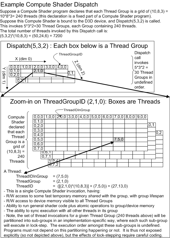
The following values are available as input to the Compute Shader to identify the current thread executing and where it is relative to all the other threads dispatched:
Each component of each ID value is a 32-bit unsigned integer.
A similar entry point is provided that takes the information about how many thread groups to dispatch from a Buffer on the GPU. When the command reaches the GPU for execution, at that time the paramters are read from the GPU Buffer. The point is that the parameters may have been written by some other GPU operation, possibly after the actual issuing of DispatchIndirect call from the CPU.
   void ID3D11DeviceContext::DispatchIndirect(
     ID3D11Buffer* pBufferForArgs,
     UINT AlignedByteOffsetForArgs ); // can be called on deferred context as well

    // At the specified offset in the Buffer, the following data members will be read:

    struct DispatchIndirectArgs
    {
    UINT NumThreadGroupsX;
    UINT NumThreadGroupsY;
    UINT NumThreadGroupsZ;
    };
If any of the DispatchIndirect arguments are 0, the Dispatch does nothing.
The upper bound on each dimension is 65535. Larger values produce undefined behavior.
If the address range in the Buffer where DispatchIndirect's parameters will be fetched from go out of bounds of the Buffer, or the starting offset is not 4-byte aligned, behavior is undefined.
The related calls for graphics are DrawInstancedIndirect(8.7) and DrawIndexedInstancedIndirect(8.8)"
With D3D10, an application had limited means of generating variable content on the GPU and then drawing it without involving the CPU threads. The main scenario supported is to generate a set of output from stream output, and then draw it with DrawAuto(8.9). DrawAuto is not easily extended to the ComputeShader as well as other more general scenarios. Allowing the application to directly specify the inputs to the draw/dispatch operation in a GPU side resource is the straightforward mechanism.
While most parameters to Draw*InstancedIndirect/DispatchIndirect can be initialized via standard ways of writing data into Buffers, such as Copy* commands, or rendering, a special-purpose Copy command is needed in some scenarios.
These scenarios involve a variable amount of data that has been written to a Buffer, via Pixel Shader/Compute Shader Unordered Access Views with Append or Counter semantics. The resource receiving the data has hidden counters that track how much has been written. One might want to issue DrawInstancedIndirect/DispatchIndirect in such a way that all of the entries in a variable length array of structures written to a Buffer are fed back into the pipeline.
To accomplish this, a new API/DDI CopyStructureCount is introduced:
void ID3D11DeviceContext::CopyStructureCount(
ID3D11Resource* pDstResource,
UINT            DstAlignedByteOffset,
ID3D11UnorderedAccessView* pSrcView) // can be called on deferred context as well
pDstResource is any Buffer resource that other Copy commands are able to write to, such as CopySubresourceRegion or CopyResource.
DstAlignedByteOffset is the offset from the start of pDstResource to write 32-bit UINT structure (vertex) count from pSrcResource.
pSrcResource is an UnorderedAccessView of a Structured Buffer resource created with either D3D11_BUFFER_UAV_FLAG_APPEND or D3D11_BUFFER_UAV_FLAG_COUNTER specified when the UAV was created. These types of resources have hidden (implementation maintained) counters tracking "how many" records have been written.
The hardware tracks a single number with an unordered access view: a UINT32 count reflecting how many times a structure was written. The count value will be copied directly to pDstResource at DstAlignedByteOffset.
When CopyStructureCount is used as a way to recirculate variable length arrays of structures back into the pipeline, the application must be aware that there is no indication of whether the Buffer holding the variable length data ran out of space. If the count is too high for the amount of space in the Buffer, it means that during initialization when the Buffer got full, subsequent writes were discarded, yet the counter continues going. The intent here is to efficiently enable scenarios where the application knows the worst case amount of data that could be written and allocates appropriately (or is otherwise somehow robust to having the last elements missing due to Buffer full). Calling Draw*Indirect with a vertex count that is too high behaves predicably – attempts to read past the end of a Buffer have well defined semantics (spec’d elsewhere).
NOTE: CopyStructureCount does not work StreamOutput resources.
Current mass-market applications for GPUs (that are not 3-D shading) are substantially GPU memory i/o bound. This means that 50-80% of the available processing power in current GPUs cannot be brought to bear on these common problems. Adding support for sharing of small amounts of data between threads can reduce the effects of this i/o bottleneck, as it allows the shader to re-use data that was already brought into registers by a previous thread. This saves the i/o work involved and allows the full processing power of the GPU’s ALUs to operate, producing a potential 4-8x performance improvement for key scenarios.
Current trends in silicon architecture will enable compute performance to grow faster than bandwidth performance. This will increase the ratio of compute performance to bandwidth performance significantly.
The hardware functionality required to address this in the DirectX11 shader model 5.0 compute shader is a predefined block of 32kB (8192 DWORDs) of register space that can be declared within a shader to be of storage class “groupShared”. Registers declared to be of this class can be shared between threads in the group.
Due to contention issues it is not ideal for all threads in a given invocation ( Dispatch() call) to access the same set of shared registers. Therefore, a mechanism is defined to partition the threads into smaller groups that can all share access to a given 32kB set of shared register space. This partitioning mechanism is a regular division. The size of the group is specified in the HLSL as specified as specified in here(18.6.13). Any thread in the subset has read-write access to any register in the shared register space.
The compiler will validate at compile time that the total amount of shared variable space declared does not exceed the limit defined for the shader model.
There is a maximum limit to the number of threads in a thread group , ie that can be permitted to exchange information through a single set of shared register space. In DirectX 11 shader model 5.0 this limit is set at 1024 threads.
These shared registers are assumed to be a physically separate from, and in addition to the pool of general purpose/temp registers, but should have similar performance characteristics (access times).
The compiler will validate usage patterns of shared memory. See here(18.6.11) for details.
Values stored in this shared memory are not preserved across/between shader invocations, nor between thread groups. They must be initialized by the shader before use, and any results to be persisted must be written out to video memory.
An explicit execution barrier intrinsic is added to compute shader HLSL to identify a barrier point. All threads within a single thread group (those that can share access to a common set of shared register space) will all be executed up to the point where they reach this barrier before any of them can continue beyond it. For example:
SynchronizeThreadGroup();
This barrier will be present in the Intermediate Language emitted by the Microsoft shader compiler. There will be cases where it is inserted by the compiler without being explicitly inserted by the shader programmer. In such cases, a warning will be issued.
A barrier intrinsic cannot appear inside of dynamic flow control. A barrier can be within uniform flow control (ie flow control based on non-per-pixel variables). The HLSL compiler will validate this and will fail compilation if barriers are placed within dynamic flow control.
No automatic mechanism for synchronizing between or enforcing ordering between thread groups is specified for implementations at this time. Synchronization across thread groups is up to the application.
For more concrete details (taking precedence over any text here) see the Shader Memory Consistency Model(7.14)
Device memory can be accessed by a compute shader for read and write operations. This section outlines the operations supported. Device memory can be defined to support read and write operations on the same surface simultaneously.
An output resource can be declared to be of one of several supported types.
(The following pseudocode may not match HLSL exactly)
Example:
RWBuffer< myFormat > OutImage;
The following resource object classes are supported for declaring output resources in HLSL compute shaders:
    RWBuffer                // a buffer for data to be written
    RWTexture1D                // a 1-D output buffer
    RWTexture1DArray        // an array of 1-D output buffers
    RWTexture2D                // a 2-D output buffer
    RWTexture2DArray        // an array of 2-D output buffers
    RWTexture3D                // a 3-D output buffer
The maximum dimensions of a resource are the same as the limits(21) on render targets for graphics with the same shader model.
Unlike texture resources, a buffer resource that is bound via a writeable shader resource view may also be read from using the correct read intrinsic. However, no resource (texture or buffer) can be bound simultaneously via writeable and readable views. The Direct3D device API implementation enforces this at buffer bind time by unbinding the conflicting view.
If a resource is swizzled at the time of being written to, then the implementation is responsible for swizzling writes to that surface.
Buffer resources used for output from the compute shader must be created with the D3D11_BIND_RENDER_TARGET flag. Such resources may be read from, however.
Buffer resources created with the D3D11_BIND_SHADER_RESOURCE flag may only be used as inputs to the compute shader.
Reading data from device (video) memory is supported using the same mechanisms as graphics shaders of the same shader model version.
For example, in shader model 5, up to 128 resources can be bound to the compute shader for read operations.
Any input port can have a resource assigned. Texture resources can be used with load(), gather(), or sample() instructions. Input resources that are buffers (not textures) can also be bound for input, but filtering operations may not be used on such resources.
Buffer resources (not texture resources) may also be read from, even though they are created as output resources.
When reading addresses outside of range, 0 is returned.
Shader threads are able to write information out to device memory using mechanisms analogous to those used by graphics shaders in stream-out, and in rendering. In addition, shaders can write data to a run-time computed address in graphics memory. This capability is sometimes referred to as scatter. Once a resource has been declared and assigned to the shader output, then a set of intrinsic methods can be used to write information out to that resource. The resource definition restricts the range of addresses that can be accessed to a clearly defined limit.
Multiple mechanisms are supported for output operations on Device Memory:
When writing to device memory, out-of-bounds array indices cause the write to be ignored, though out of bounds offsets within individual structs cause the entire contents of the resource to be undefined.
Note: The Pixel Shader(16) specification also includes the output operations to device memory as described here. The total number of such buffer and all MRTs is specified to be no more than a fixed limit of 8.
Random access writes to device memory are accomplished via the IL instructions: store_raw(22.4.11), store_uav_structured(22.4.13), or store_uav_typed(22.4.9) depending on the type resource is used (bound as an Unordered Access View(5.3.9)).
One way to do writes to device memory is through defined reduction operations known to be order-independent. These operations must be atomic (in the sense that they must complete fully before another thread executes on the same data), however, they do not return the result of the incremented address back to the shader code.
Atomic operations in the shader IL are listed here(22.1.2.14), named atomic_*.
These operators never return a result.
It is required that implementations make these operations atomic, ie no other thread can access the same location during the execution of this intrinsic.
Updates to device memory are also enabled through immediate reduction operations, i.e. that immediately return a result to the shader for use by subsequent instructions in the same thread. These operations must be atomic (in the sense that they must complete fully before another thread executes on the same data).
Immediate atomic operations in the shader IL are listed here(22.1.2.14), named imm_atomic_*.
The result returned by these intrinsics is the value of the destination before the operation is performed. There is at least one exception where the value after the operation was performed is returned: imm_atomic_consume(22.17.18).
A capability is provided to enable threads to efficiently emit records (structs) to a compacted stream in device memory with no guarantee of ordering.
See the Append buffer(5.3.10) section.
When all elements in a wave-front write 32-bit quantities sequentially to global memory, writes should be as performant as a pixel shader writing to a render target.
A shader intrinsic is provided to force completion of all writes queued from the currently executing thread group.
A compute shader requires the ability to read and write data, and to access state information that may be updated between invocations. Data resources are managed using the same scheme as the graphics API.
In addition to the conventional texture resource binding that are common to all shader stages, such as the 128 Shader Resource View bindpoints, 8 surfaces can be bound as output texture resources (Unordered Access Views(5.3.9)) for which scattered read/write and atomic operations are permitted.
One limitation on typed texture2D UAVs is that Automatic gamma conversion to/from gamma-corrected texture formats (e.g. DXGI_FORMAT_R8G8B8A8_UNORM_SRGB) is not supported when accessed by the compute shader. Any gamma conversion required by the application must be implemented in shader code. Another limitation due to the hardware of this generation is that for typed UAVs, writes as supported, but not reads, unless the format is DXGI_FORMAT_R32_UINT/SINT/FLOAT (in which there is no type conversion required).
Shared memory can be updated via either variable assignment, variable reduction operations, or through indexed array assignment as defined below.
Shared memory registers can be updated using standard scalar variable assignment, which the implementation guarantees is atomic.
One way to perform writes to shared memory are through defined reduction operations known to be order-independent. These operations must be atomic (in the sense that they must complete fully before another thread executes on the same data), however, they do not return the result of the incremented address back to the shader code.
Atomic operations in the shader IL are listed here(22.1.2.14), named atomic_*.
These operators never return a result.
It is required that implementations make these operations atomic, ie no other thread can access the same location during the execution of this intrinsic.
Updates to shared memory are also enabled through immediate reduction operations, i.e. that immediately return a result to the shader for use by subsequent instructions in the same thread. These operations must be atomic (in the sense that they must complete fully before another thread executes on the same data).
Immediate atomic operations in the shader IL are listed here(22.1.2.14), named imm_atomic_*.
The result returned by these intrinsics is the value of the destination before the operation is performed.
For example, the compute shader can use such an intrinsic to atomically increment a shared address. This is commonly used to compact data into device memory. Below is pseudo code for how it might be exposed in the API. Behind the scenes the hardware could apply parallel constructs to make this fast.
GroupSharedSharedBase = 0; void main() { [ … load data into MyStruct and set bWillWrite … ] If (bWillWrite) { // all the magic can happen for InterlockedIncrement under the covers MyBaseValue = SharedBase.Add(1); MySharedArray[MyBaseValue] = MyStruct; } }
Although this intrinsic updates the contents of the shared register used, the return result of the intrinsic is the pre-operation modified value.
Note: In DX11 shader model 5.0, these intrinsic are only supported on 32-bit integer shared memory variables.
Arrays declared in shared memory can be written to directly via write/copy operations or the above reduction operators using indexed array assignment.
Shared memory should be performant when all elements of a wave front are writing out sequential 32 bit quantities. Writes should not have to serialize when threads write non-sequentially to shared memory.
The following registers are available in the cs_5_0 model:
| Register Type | Count | r/w | Dimension | Indexable by r# | Defaults | Requires DCL |
|---|---|---|---|---|---|---|
| 32-bit Temp (r#) | 4096 (r# + x#[n]) | r/w | 4 | n | none | y |
| 32-bit Indexable Temp Array (x#[n]) | 4096 (r# + x#[n]) | r/w | 4 | y | none | y |
| 32-bit Thread Group Shared Memory (g#[n]) | 8192 (sum of all shared memory decls for thread group) | r/w | 1(can be declared various ways) | y | none | y |
| Element in an input resource (t#) | 128 | r | 1 | n | none | y |
| Sampler (s#) | 16 | r | 1 | n | none | y |
| ConstantBuffer reference (cb#[index]) | 15 | r | 4 | y(contents) | none | y |
| Immediate ConstantBuffer reference (icb[index]) | 1 | r | 4 | y(contents) | none | y |
| ThreadID (vThreadID(23.11).xyz) | 1 | r | 3 | n | n/a | y |
| ThreadGroupID (vThreadGroupID(23.12).xyz) | 1 | r | 3 | n | n/a | y |
| ThreadIDInGroup (vThreadIDInGroup(23.13).xyz) | 1 | r | 3 | n | n/a | y |
| ThreadIDInGroupFlattened (vThreadIDInGroupFlattened(23.13)) | 1 | r | 1 | n | n/a | y |
| Output Registers: | ||||||
| NULL (discard result, useful for ops with multiple results) | n/a | w | n/a | n/a | n/a | n |
| Unordered Access View (u#) | 64 | r/w | 1 | n | n | y |
For graphics shaders the maximum number of general purpose/temporary registers per thread is set at 4096 float4s. This limit remains the same for each thread in the Compute Shader.
In practice, hardware implementations may spill temp register storage to slower memory behind the scenes if the combination of # of temps per thread and # of threads in the group goes too high. Functionally, however, it will always appear to the shader as if storage for 4096 temp registers is available per Compute Shader thread independent of how many threads are in a group.
The HLSL compiler may blindly print a warning (not an error) when the number of temps used by a Compute Shader exceeds the threshold: min(16384 / threads in group, 4096). This is just a rough guess that spilling of temp storage is likely to happen beyond this point, but it could even happen with fewer temps. Such a warning does not take into account the actual threshold(s) where the number of temps impacts performance on any given hardware architecture.
The compute shader supports two different areas where order-dependent results can arise. Threads may contend for the same write address in both the shared memory register space, and in the output memory resource. Separate mechanisms can be offered as outlined below. These mechanisms are not defined in detail in this functional spec as their syntax can be decided by the programmer.
It is the intent that this functional specification enable much more freedom than may be exposed in initial versions of the compiler. This will enable compiler updates to expose more general functionality over time, if such is discovered to be sufficiently important.
The compiler can identify 3 separate cases for the addresses written into shared memory (indices of arrays declared in the shared register space).
1. If these addresses are known to not overlap, (e.g. are computed solely based on the vThreadID and some constants and no mod () operations, then compilation will succeed.
2. If these addresses are known to repeat and will overlap then compilation will fail with a fatal error.
3. If these addresses cannot be determined to be free of conflict, the compiler will issue a warning
In the case where the operation on the destination is a reduction operator (such as an atomic add), then the compiler need not validate the address computation logic. In this case collisions will not produce order-dependent output, but programmers need to be aware that they may still produce performance issues due to port contention, or locks taken by the implementation to assure atomicity of the operator.
The same mechanisms are available as used in the Shared Register Space validation above.
It is illegal to have a loop inside of a divergent branch with termination dependent on thread communication. This is to prevent deadlock and will be validated by the HLSL compiler.
For optimal performance, it is expected that the number of threads per group is between 200 and 1024 for shader model 5. The number of thread groups per invocation should be over 128 ideally.
All API state for the Compute Shader is unique to it, just as Pixel Shader state is kept separate from Vertex Shader state. This state is of the following four categories:
Like any other shader type, there are methods on the D3DDevice to specify the additional state specific to the compute shader:
pD3D11Device->CSSetShaderResources()
        -bind memory resources of buffer or texture type

pD3D11Device->CSSetConstantBuffers()
        -bind read-only buffers that store data that does not change during shader execution

pD3D11Device->CSSetSamplers()
        -apply state that governs how any texture resources bound are sampled

pD3D11Device->CSSetShader()
        -bind the compute shader object
The syntax for these methods is the same as the corresponding calls for other Direct3D11 shaders.
All state of the compute shader is like state for any other shader and is independent of the state of all other shaders.
The following example shows how the thread count is specified as an attribute in HLSL.
[numThreads(10,8,3)] void CS( … )
{
    Shader Code
}
As a convenience to the programmer, sets of threads in an invocation batch can be thought of as being organized into an array of 1-, 2-, or 3-dimensions (with the possibility of more in future releases).
To continue the above example, the shader could be invoked with the following parameters in the dispatch call:
pD3D11Device->Dispatch( 5, 3, 2 );
This launches a grid of 30 groups that is 5 groups wide by 3 groups high, by 2 group deep. Each group contains a block that is 10 threads wide by 8 threads high by 3 deep.
The diagram here(18.6.3) shows what this would look like, including thread ID's in the Compute Shader threads that identify where they are.
In DirectX11 shader model 5.0, there is an upper limit of 64 on the last dimension (Z) of the thread group thread counts. Any 5.0 shaders that specify a larger value here will fail compilation.
// Basic Example

// Bind shader that does one iteration and updates vidmem buffer pDispatchCount with
// estimated nr of threads required to finish the task.
pD3D11Device->CSSetShader( hIterationShader );

// launch first unit of work.
pD3D11Device->Dispatch( 32, 32, 1 );

// Always queue MAXITERATIONS dispatch calls
// Those that have 0 in DispatchCount will no-op
for ( i=0; i<MAXITERATIONS; i++ )
{
pD3D11Device->DispatchIndirect( pBufferDispatchCount, 0 );
}
// Note: MAXITERATIONS is determined by how long we can afford to spend on this.

A slightly more complex example:

// This example uses 2 shaders in the loop:
//    One to do the heavy math,
//    and the other to evaluate convergence (via some reduction step)
//    and update the expected nr of threads for the next call.

// Launch first unit of work.
// Bind then execute shader that does one iteration of conjugate gradient
pD3D11Device->CSSetShader( hMatMulShader );
pD3D11Device->Dispatch( 32, 32, 1 );
// Bind then execute shader that evaluates whether we are converged,
//    and updates estimated thread count in pBufferDispatchCount
//    so that next call knows how many threads to dispatch.
pD3D11Device->CSSetShader( hReduceShader );
pD3D11Device->Dispatch( 32, 32, 1 );

// Always queue MAXITERATIONS DispatchIndirect() calls
for ( i=0; i<MAXITERATIONS; i++ )
{
// Bind then execute shader that does one iteration of conjugate gradient
pD3D11Device->CSSetShader( hMatMulShader );
pD3D11Device->DispatchIndirect( pBufferDispatchCount, 0 );

// Bind then execute shader that evaluates whether we are converged
pD3D11Device->CSSetShader( hReduceShader );
pD3D11Device->DispatchIndirect( pBufferDispatchCount, 12 );

// Updates estimated thread count by writing it into pBufferDispatchCount.
pD3D11Device->CSSetShader( hEvaluateConvergenceShader );
pD3D11Device->DispatchIndirect( pBufferDispatchCount, 24 );


}
// Note: MAXITERATIONS is determined by how long we can afford to spend on this.


Sample shader snippet for 2nd shader in this example:

EvaluateConvergence()
{
    OutputBuffer DispatchCountBuffer;    // buffer to write to when we are done
    InputBuffer ResidualBuffer;        // buffer containing value of residual
                            // as computed by a previous reduction shader

float residual = ResidualBuffer.load( 0 );

    if ( threadID == 0 )                // Don’t bother doing this more than once
    {
        if ( residual < ERR_TOLERANCE )    // if residual is small enough
        {
            // Clear out the dispatch count buffer used by 1st shader (math)
            DispatchCountBuffer.Write(  0, 0 );
            DispatchCountBuffer.Write(  4, 0 );
            DispatchCountBuffer.Write(  8, 0 );

            // Clear out the dispatch count buffer used by 2nd shader (reduction)
            DispatchCountBuffer.Write( 12, 0 );
            DispatchCountBuffer.Write( 16, 0 );
            DispatchCountBuffer.Write( 20, 0 );
        }
    }

}
Section Contents
(back to chapter)
18.7.1 Overview
18.7.2 How Relevant D3D11 Features Work on Downlevel HW
This section defines a subset of the D3D11 hardware Compute Shader as well as Raw(5.1.4) and "Structured Buffer(5.1.3) features that can work on some D3D10.x hardware. D3D11 drivers on D3D10.x hardware can opt-in to supporting this functionality via the D3D11 API. No changes were made to the D3D10.x API/DDIs for this.
Example of known D3D10.x hardware that should be able to support this at the time of implementation are all of nVidia’s D3D10+ hardware, and for AMD, all 48xx Series D3D10.1 hardware and beyond. The features exposed are basically an intersection of the features on known existing hardware, while being a clean subset of D3D11 hardware’s feature set. The feature intersection does mean that not all of the expressiveness of IHV-specific APIs is available.
The rest of this section refers to D3D11 drivers for D3D10.x hardware which have opted into supporting the features as "downlevel HW". Note this does not mean all D3D10.x hardware.
The Dispatch() API/DDI on D3D11 for invoking the Compute Shader will function identically on downlevel HW, with the X and Y dimensions of the grid of Thread Groups invoked allowed to be up to 65535, however the Z dimension can be no more than 1 (larger gives undefined behavior), as opposed to 65535 on D3D11 hardware.
DispatchIndirect() is unsupported on downlevel HW, so the runtime will do nothing on such HW when this API is called.
The CSInvocations pipeline statistic(20.4.7) will count identically for downlevel and D3D11 HW. Given that DispatchIndirect() is not available on downlevel HW, this is admittedly not of much value, since the application can trivially track how many threads it invoked via Dispatch() calls.
Downlevel HW supports Raw and Structured UAVs (but not Typed UAVs) with identical semantics to D3D11 HW, except that only a single UAV can be bound to the pipeline at a time via CSSetUnorderedAccessViews() API/DDI.
Note the lack of support for Typed UAVs on downlevel HW also means that Texture1D/2D/3D UAVs are not supported.
Pixel Shaders on downlevel HW do not support UAV access.
The base offset for a RAW UAV must be 256 byte aligned (whereas full D3D11 HW requires only 16 byte alignment). RAW SRV’s (below) do not have any corresponding additional restriction.
All shader stages on downlevel HW: Vertex Shader, Geometry Shader, Pixel Shader and Compute Shader (CS described later) support binding Raw and Structured Buffers as SRVs for read-only access, just as on D3D11 hardware.
This is useful not only as a way of re-circulating Compute Shader outputs, but also in general as a way of reading generic data into Shaders.
When downlevel HW support is available, existing D3D10/D3D10.1 shader models 4_0 and 4_1 gain additional functionality via D3D11. The reason this additional functionality is not placed in a separate shader model (such as defining a new 4_3 model) is that some of the targeted hardware is 4_0 class, and some is 4_1 class. So these additional features are orthogonal to shader models.
This way of exposing additional functionality to a given shader model is similar to the way double precision instruction support is made available optionally through shader model 5_0.
For VS/GS/PS 4_0/4_1, the additional functionality is the ability to read from raw and structured buffers, described earlier. This means the addition of the following bytecode instructions from shader model 5 are added to these shader models:
Beyond the VS/GS/PS, an additional shader type is available on downlevel HW: Compute Shader, via shader models CS_4_0 and CS_4_1. The next section describes this in detail.
CS_4_0 takes the VS_4_0 instruction set, except it has Compute Shader style inputs:
The output is a single UAV, u#, where # is the RT/UAV slot where the UAV is bound. vThreadIDInGroupFlattened is defined later on (it has not been described before) – it will also be in CS_5_0 for forward compatibility.
CS_4_1 is like CS_4_0, except it uses the VS_4_1 instruction set instead of VS_4_0.
For both CS_4_0 and CS_4_1, the following additional instructions are present:
Note in particular the absence of atomic operations, append/consume, or typed UAV access from the above list. All of these are present in CS_5_0.
Further, note the absence of double precision arithmetic operations – drivers may opt to expose double precision arithmetic operations support via 5_0 shaders, but even if that is the case, CS_4_0 does not expose doubles (nor do any 4_x shaders for that matter).
The sync instruction behaves the same as in CS_5_0, including the stipulation that the _ugroup option will not be exposed via HLSL unless it is deemed necessary (see sync instruction specs).
Downlevel HW supports X and Y dimensions of at most 768 for the set of threads in the Thread Group (as opposed to 1024 for D3D11 HW). The Z dimension is unchanged at a maximum of 64.
The total number of threads in the group (X*Y*Z) is limited to 768, as opposed to 1024 for D3D11 HW.
Exceeding these limits is enforced simply by failing shader compilation, since the numbers are declared as part of the shader.
There is only 16kB total Thread Group Shared Memory on downlevel HW, as opposed to 32kB for D3D11 HW.
A given Compute Shader thread can only write to its own region of TGSM. This write-only region has a maximum size of 256 bytes or less, depending on the number of threads declared for the group. This per-thread size maximum is given by the table below. Instructions that write to the shared memory must use a literal offset into the region.
| Number of Threads in Group | Max Thread Group Shared Memory Writable per Thread (Bytes) |
|---|---|
| 0..64 | 256 |
| 65..68 | 240 |
| 69..72 | 224 |
| 73..76 | 208 |
| 77..84 | 192 |
| 85..92 | 176 |
| 93..100 | 160 |
| 101..112 | 144 |
| 113..128 | 128 |
| 129..144 | 112 |
| 145..168 | 96 |
| 169..204 | 80 |
| 205..256 | 64 |
| 257..340 | 48 |
| 341..512 | 32 |
| 513..768 | 16 |
In contrast, any thread can read the TGSM for the entire thread group.
Accesses to UAVs from cs_4_0/cs_4_1 do not have these constraints.
First, recall that in cs_5_0, the Thread Group Shared Memory (TGSM) space is made visible to compute shader threads by declaring ranges of the space, each named g#. All threads can see all the g# ranges. The reason to be able to define multiple g# is to allow different ranges to be organized differently – like with different structure strides. A given g# range can be declared as either RAW (just a flat count of bytes in size, multiple of 4 bytes), or STRUCTURED (given a structure count and a structure stride that is a multiple of 4 bytes).
For cs_4_0 and cs_4_1, RAW g# memory is not available at all. All g# declarations must be STRUCTURED, but as a way of exposing per-thread RAW memory, rather than as a way of having an array of structures that a given thread could write to.
Recall that STRUCTURED g# declarations look like:
dcl_tgsm_structured g#, numStructures, structureByteStride
Recall the Compute Shader declares its thread group size statically via 3 integers defining the dimensions of the grid of threads – x,y,z. The number of threads in the group is x*y*z.
For CS_4_0/4_1, it is required that numStructures in the dcl above must be exactly x*y*z. And it is required that the sum of the structureByteStride value for all g# declarations in the program falls within the size limits defined in the previous section.
Recall that the Compute Shader has an input System Generated Value(4.4.4) (SGV) "vThreadIDInGroup" which tells the thread where it is in the grid as a 3D value.
A new input SGV is introduced now, for CS_4_0, CS_4_1 and CS_5_0 (forward compatibility): "vThreadIDInGroupFlattened(23.14)". This is the 1D equivalent of vThreadIDInGroup:
vThreadIDInGroupFlattened = vThreadIDInGroup.z*y*x + vThreadIDInGroup.y*x + vThreadIDInGroup.x.
It is required that any writes to g# memory in CS_4_0 and CS_4_1, which must be done via the store_structured instruction, must specify the structureIndex parameter as vThreadIDInGroupFlattened, and the byte offset must be a literal.
e.g.
store_structured g3.xy, /* output */
                 vThreadIDInGroupFlattened.x, /* structure index */
                 4, /* literal byte offset */
                 r0.zw /* source */
Just as optional double precision math support in shader model 5 is reported through the CheckFeatureSupport API/DDI, in the same way a driver can report support for the Compute Shader and Raw/Structured Buffers on Shader 4_x. The support is all or none.
The particular bit in the caps structure reported by drivers, shown below, is D3D11DDICAPS_SHADER_COMPUTE_PLUS_RAW_AND_STRUCTURED_BUFFERS_IN_SHADER_4_X. D3D11 Hardware must report this bit, as it represents a subset of D3D11’s features.
typedef struct D3D11DDI_SHADER_CAPS
{
    UINT Caps; // D3D11DDICAPS_SHADER_*
} D3D11DDI_SHADER_CAPS;
// Caps
#define D3D11DDICAPS_SHADER_DOUBLES 0x1
#define D3D11DDICAPS_SHADER_COMPUTE_PLUS_RAW_AND_STRUCTURED_BUFFERS_IN_SHADER_4_X 0x2
This information is bubbled up to the D3D11 API via CheckFeatureSupport(), where there is an entry in the D3D11_FEATURE enum: D3D11_FEATURE_D3D10_X_HARDWARE_OPTIONS
The data structure associated with this feature query would be:
typedef struct D3D11_FEATURE_DATA_D3D10_X_HARDWARE_OPTIONS
{
    BOOL ComputeShaders_Plus_RawAndStructuredBuffers_Via_Shader_4_x;
} D3D11_FEATURE_DATA_D3D10_X_HARDWARE_OPTIONS;
CS_4_0 and CS_4_1 shaders and Raw or Structured Buffers will be allowed to be created on devices that report TRUE for ComputeShaders_Plus_RawAndStructuredBuffers_Via_Shader_4_x.
To enable use of Raw/Structured Buffers as SRVs in VS, GS or PS, a new flag can be present in the following shader models: VS_4_0, VS_4_1, GS_4_0, GS_4_1, PS_4_0, PS_4_1. Recall that at the IL level, shader 4_0+ already has a "global flags" declaration: dcl_globalFlags(22.3.2). In D3D10.x APIs the only flag that could be specified here is REFACTORING_ALLOWED. For all the shader models listed in this paragraph an additional flag can be used (only with the D3D11 APIs):
D3D11_SB_GLOBAL_FLAG_ENABLE_RAW_AND_STRUCTURED_BUFFERS
Shaders that set this flag will only be allowed to be Created on a device that reports TRUE for ComputeShaders_Plus_RawAndStructuredBuffers_Via_Shader_4_x.
The Dispatch() API will be dropped by the runtime for devices that do not report TRUE for ComputeShaders_Plus_RawAndStructuredBuffers_Via_Shader_4_x. As mentioned previously, DispatchIndirect() will always be dropped on pre-D3D11 hardware.
Chapter Contents
(back to top)
19.1 Formats
19.2 Multisample Format Support
19.3 Compressed HDR Formats
19.4 Sub-Sampled Formats
19.5 Block Compression Formats
19.6 Resurrected 16-bit Formats from D3D9
19.7 ASTC Formats
Summary of Changes in this Chapter from D3D10 to D3D11.3
Back to all D3D10 to D3D11.3 changes.(25.2)
Section Contents
(back to chapter)
19.1.1 Overview
19.1.2 Data Invertability
This section describes D3D11.3 Element(4.4) data format layout and interpretations. A large number of data layouts and interpretations are available. In addition, there is facility to view the same data with different interpretations (e.g. raw bits vs. normalized integer), or to represent data in a general way (just the bit layouts) without committing to a particular interpretation of the data (e.g. normalized) until as late as possible (e.g. a Shader using the data).
In D3D11.3, it is possible to create partially typeless where the number of bits per component is specified, but not the data interpretation for those bits. An example of a partially typeless format is DXGI_FORMAT_R8G8B8A8_TYPELESS. This format has several subformats (making up a second tier) which fully resolve the interpretation of the data, including DXGI_FORMAT_R8G8B8A8_UNORM, DXGI_FORMAT_R8G8B8A8_UNORM_SRGB, among others.
When a resource with a partially typeless format is bound to a Shader for output or input, it must be fully qualified as one of the subformats which has the same bit counts for each component but now defines a specific type for each components.
Since partially typeless formats have the number of bits per Element (BPE) specified, resource dimensions provided on creation are enough to determine memory allocation requirements. Note that some complex formats, such as Block Compression(19.5) formats, require the format to be specified permanently on resource creation.
D3D11.3 defines a long list of Element format names (the DXGI_FORMAT_* enum below). Each format which does not have TYPELESS in its name describes the data representation at both ends (source/target) when transferring data from a resource Element into a Shader register or transporting data from a Shader register out to a resource. Sometimes the transport path involves some mathematical operations in the middle (such as filtering or blending), but such middle steps do not change what the data is to be represented as at both ends of the transport, as defined by the DXGI_FORMAT_*. Should there be ambiguity regarding how to go about intermediary steps (filtering or blending) for particular formats, it will likely be clarified in this spec, and certainly in the D3D11.3 reference rasterizer.
Consider a number expressed in some data format sitting in memory.
Suppose this number travels along the following path: First it is input into a Shader by a mechanism that does no other transformation on the data (exampes: sampling without filtering, or an Input Assembler fetch) except perhaps conversion into a format compatible with the target Shader register. Then, the value is passed from Shader to Shader in the Pipeline unmodified. Finally, this unmodified value sitting in a Shader is written back out to memory by a mechanism that does no other transformation on it (i.e. blending disabled when rasterizing) except perhaps conversion to the output format.
Other examples of operations on read or write that qualify in the path above are:
D3D11.3 requires that for the path described, if the output data format is the same as the original input format, then the input and the output data must be identical in memory.
The naming convention followed by most formats (aside from special formats like Block Compression (BC*)(19.5) Formats, or YUV among others) in the table below is as follows:
R/G/B/A   - Refers to Shader register components (source component on write
            out from a Shader, or pre-swizzle destination component on read
            into a Shader).
D/S       - Refers to Depth/Stencil for formats that are to be used
            as such.
X         - Unused bits in format.
#         - Refers to number of bits in component.

Channel ordering of R/G/B/A/D/S/X in format name, read from left to right
indicates order of placement of the channel storage from "first" (left)
to "last" (right).

Formats are defined to be compatible across host CPU architectures, especially
host CPU architectures that are litte or big endian. In general, components
which come "first" are located at lower addresses, while "later" components are
located at higher addresses. This means that, for example, DXGI_FORMAT_R8G8B8A8_*
is interpreted as:

( ElementAddress + 0 ) : R8
( ElementAddress + 1 ) : G8
( ElementAddress + 2 ) : B8
( ElementAddress + 3 ) : A8

This means that the CPU can treat the R8G8B8A8 Element as an array of byte-sized
components, which is a memory layout that is compatible with popular programming
languages implemented on multiple host CPU architectures. When components grow
larger than a byte, like DXGI_FORMAT_R32G32B32A32, later components are still
located at larger addresses than earlier components. However, the component
is still specified in LSb/ MSb format, so respects the host CPU byte-endianness:

( ElementAddress +  0 ) : R32
( ElementAddress +  4 ) : G32
( ElementAddress +  8 ) : B32
( ElementAddress + 12 ) : A32

R32 : 32 bits, matching the CPU byte-endianness.
LE R32 =>                  MSb                 LSb
( ComponentAddress + 0 ) = 07:06:05:04:03:02:01:00
( ComponentAddress + 1 ) = 15:14:13:12:11:10:09:08
( ComponentAddress + 2 ) = 23:22:21:20:19:18:17:16
( ComponentAddress + 3 ) = 31:30:29:28:27:26:25:24
BE R32 =>                  MSb                 LSb
( ComponentAddress + 0 ) = 31:30:29:28:27:26:25:24
( ComponentAddress + 1 ) = 23:22:21:20:19:18:17:16
( ComponentAddress + 2 ) = 15:14:13:12:11:10:09:08
( ComponentAddress + 3 ) = 07:06:05:04:03:02:01:00

Naturally, such a specification only works well for certain formats. As long as
the format components are uniform (all have the same size), the component size
is a power of two, and the component size is a multiple of 8 bits. When such
conditions are not met, the memory layout specification must resort to a least
significant bit/ most significant bit definition of the entire element,
when the element size is a multiple of 8 bits.

R10G10B10A2: 32-bit Element
R: bits  0- 9
G: bits 10-19
B: bits 20-29
A: bits 30-31

Certain formats do not comply with these rules, because they are considered
custom formats. An example of such formats is the block compression formats.
Such custom formats have memory layout definitions of their own, seperate
from the general rules. R1 formats also have their own seperate definition.
Note, this means that to first-class support multiple CPU architectures, the implementation of the specification must adapt component endianness to match the host CPU. For those formats which are specified in a least significant bit/ most significant bit definition, the implementation must adapt the overall element endianness to match the host CPU.
_SNORM    - Data in channels appearing on the left of _SNORM in the
            format name are interpreted in the resource as signed integers,
            and in the Shader as signed normalized float values
            in the range [-1,1].  Conversions are defined here:
            FLOAT -> SNORM(3.2.3.4)
            SNORM-> FLOAT(3.2.3.3)
_UNORM    - Data in channels appearing on the left of _UNORM in the
            format name are interpreted in the resource as unsigned integers,
            and in the Shader as unsigned normalized float values,
            in the range [0,1]. Conversions are defined here:
            FLOAT -> UNORM(3.2.3.6)
            UNORM -> FLOAT(3.2.3.5)
_SINT     - Data in channels appearing to the left of _SINT in the
            format name are interpreted both in the resource and in the
            Shader as signed integers.  Conversions are defined here:
            SINT -> SINT (With More Bits)(3.2.3.9)
            SINT or UINT -> SINT or UINT (With Fewer or Equal Bits)(3.2.3.13)
_UINT     - Data in channels appearing to the left of _UINT in the
            format name are interpreted in the resource as unsigned integers,
            and also in the Shader as unsigned integers.  Conversions are
            defined here:
            UINT -> UINT (With More Bits)(3.2.3.12)
            SINT or UINT -> SINT or UINT (With Fewer or Equal Bits)(3.2.3.13)
_FLOAT    - Data in channels appearing to the left of _FLOAT in the format name
            are interpreted in the resource as floating point values (bit depth
            specified by format), and in the Shader as 32 bit floating point
            values, with appropriate conversions either way.  Conversions
            are defined here: Floating Point Conversion(3.2.2)
_SRGB     - R, G and B channels in format store Gamma 2.2f data.  Conversion
            to/from Gamma 1.0f is required (pre-filtering) when
            reading/writing data to those channels.  Conversions are defined
            here:
            SRGB -> FLOAT(3.2.3.7)
            FLOAT -> SRGB(3.2.3.8)
            If a format with _SRGB has an A channel, the A channel is stored in Gamma 1.0f.
            This modifier is ignored for display scan-out (see SRGB Display Scan-Out(19.1.3.4)).
_TYPELESS
          - Typeless format with the component bit counts specified.  When the
            resource is bound to a Shader, the application or Shader must resolve what
            format to interpret the data as (format must have same bits per
            component distribution).
The default value for missing components in an Element format is "0" for any component except A, which gets "1". The way "1" appears in the Shader depends on the Element format, in that it takes the specified data interpretation of the first typed component that is actually present in the format (starting from the left in RGBA order). If this interpretation is UNORM or FLOAT, then 1.0f is used for missing components. If the interpretation is SINT or UINT, then 0x1 is used.
For example, when the format DXGI_FORMAT_R24_UNORM_X8_TYPELESS is read into a Shader, the values for G and B are 0, and A is 1.0f. For DXGI_FORMAT_R16G16_UINT, the B gets 0 and A gets 0x00000001. DXGI_FORMAT_R16_SINT provides 0 for G and B, and 0x00000001 for A.
The _SRGB format modifier is ignored for display scan-out, so for the purposes of scan-out the _SRGB and non-_SRGB formats are identical. It is up to the application to appropriately set the display scan-out controls to accommodate _SRGB formats.
The following links are to Excels spreadsheets with a complete listing of available D3D11.3 formats, by feature level.
D3D11_3_Formats_FL9_1.xls(outside link)
D3D11_3_Formats_FL9_2.xls(outside link)
D3D11_3_Formats_FL9_3.xls(outside link)
D3D11_3_Formats_FL10_0.xls(outside link)
D3D11_3_Formats_FL10_1.xls(outside link)
D3D11_3_Formats_FL11_0.xls(outside link)
D3D11_3_Formats_FL11_1.xls(outside link)
The meaning of the column, "Cast within Bit Layout" is that Pre-Structured+Typeless(5.1.5) or Prestructured+Typed(5.1.6) resources having a particular format can have the format reinterpreted using a Resource View(5.2) to be any other format, as long as the number of bits per-component are identical, but interpretations of the bits can be different. The new format must be compatible with the usages (such as RenderTarget) specified when originally creating the resource.
Section Contents
(back to chapter)
19.2.1 Overview
19.2.2 Multisample RenderTarget/Resource Load Support vs. Multisample Resolve Support
19.2.3 Optional Multisample Support
19.2.4 Specification of Sample Positions
Observe in the Format List(19.1.4) that a superset of formats that support Multisample resolve can be used for Multisampling. For example, integer formats do not have a fixed-function resolve permitted, yet they can still be supported for Multisample resources. The point is that these formats can be used as RenderTargets and subsequently be read back into shaders via Multisample Resource Load(7.17.1); a path where no resolving of the Multisample resource is needed given the individual samples are accessed by the shader. Note that depth formats are not supported for multisample resource load and are thus restricted to be RenderTargets only.
Typeless formats such as R8G8B8A8_TYPELESS support multisampling as well, to enable blindly interpreting the data in the resource different ways. Note that this ability to change the format interpretation of a resource is pervasive in the system; Multisampling happens to be one instance where the concept applies. A specific example with Multisampling would be to create a Multisample resource with the format R8G8B8A8_TYPELESS, render to it resource with a R8G8B8A8_UINT RenderTarget View, then later resolve the contents to another resource by telling the Resolve operation that the data format is R8G8B8A8_UNORM. Note that R8G8B8A8_UNORM can support Multisample Resolve, while R8B8B8A8_UINT cannot. No data conversion happens from UINT to UNORM for this example, just raw interpretation of the data as UNORM (ignoring that it happened to be rendered as UINT). The application is assumed to be taking advantage of this behavior by requesting it.
Observe in the Format List(19.1.4) that Multisample support appears optional for a large set of formats, never required. The meaning of this is as follows:
Hardware can report support or non-support of Multisampling for any format listed in the format list. This is exposed through the API/DDI via a method for hardware to report, for any given format + sample count (up to 32 samples), a number indicating how many "Quality Levels" are supported. For example R8G8B8A8_UNORM with 2-sample Multisampling may support 3 quality levels on some hypothetical hardware implementation. This means the hardware happens to support 3 different sample layouts and/or resolve algorithms for 2-sample Multisampling for R8G8B8A8_UNORM. The definition of each reported Quality Level is up to the hardware vendor to define, however no facility is provided by D3D to help discover this information.
Hardware can report 0 quality levels for a given format + sample count, which means the hardware does not support multisampling at all for that combination of format + sample count.
There are some limitations in the flexibilty given to hardware for not supporting Multisampling on a format:
(1) Given any related family of formats sharing a typeless parent, for example the set {R8G8B8A8_TYPELESS, R8G8B8A8_UNORM, R8G8B8A8_UNORM_SRGB, R8G8B8A8_UINT, R8G8B8A8_SNORM, R8G8B8A8_SINT}, the reported set of quality levels for each sample count for any one format in the family must be the same for the rest of the formats in the family.
(2) Any format that supports multisampling and which has type _UNORM, _UNORM_SRGB, _SNORM or _FLOAT must support Resolve. This is reflected in the Format List(19.1.4) in that Resolve support is shown as "Required" for such formats. Of course, if the hardware does not report Multisampling support for some formats at all, the "Required" Resolve support becomes moot for those formats.
In addition to the "Quality Level" mechanism for IHVs to expose custom multisample modes, as of D3D10.1, fixed sample patterns are defined for certain sample counts. For IHVs that expose the fixed patterns, sample postions will be at known locations defined here, and thus consistent across IHVs. If the hardware is asked to perform a Resolve() on a fixed pattern, that is defined as a simple average of the samples within each pixel. For every fixed sample pattern that has sample locations spread over the area of a pixel, there is a sibling fixed pattern with the same number of samples, except with all samples located overlapping the center of the pixel.
Applications can check for support of standard patterns via the exising CheckFormatSupport() method, in the following slightly awkward way: As long as the driver reports NumQualityLevels *gt; 0, and there are fixed sample patterns defined for that sample count, then the application can request the fixed patterns by specifying QualityLevel as either D3D11_STANDARD_MULTISAMPLE_PATTERN (0xffffffff) or D3D11_CENTER_MULTISAMPLE_PATTERN (0xfffffffe). In the DDI the name for these QualityLevel values are (D3D10.1 DDI names still apply) D3D10_1_DDIARG_STANDARD_MULTISAMPLE_PATTERN and D3D10_1_DDIARG_CENTER_MULTISAMPLE_PATTERN. When the driver reports NumQualityLevels > 0, this exposes support of the usual range of QualityLevel values [0... (NumQualityLevels-1)] in addition to the new fixed patterns. If the hardware only supports the fixed patterns but no additional vendor-specific patterns, NumQualityLevels can be reported as 1, and the hardware can pretend QualityLevel = 0 behaves the same as QualityLevel = D3D11_STANDARD_MULTISAMPLE_PATTERN.
Standard sample patterns are defined for the following sample counts: 1(trivial), 2, 4, 8, 16. As stated here(19.2.5), the only sample counts required by hardware are 1 and 4 and 8 samples (with some caveats). Vendors can expose any sample counts beyond these, but if they happen to support 2, 4(required), 8(required) or 16 each of those means support for the corresponding standard pattern or center pattern is required.
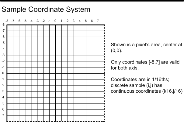
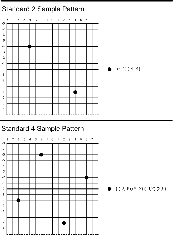
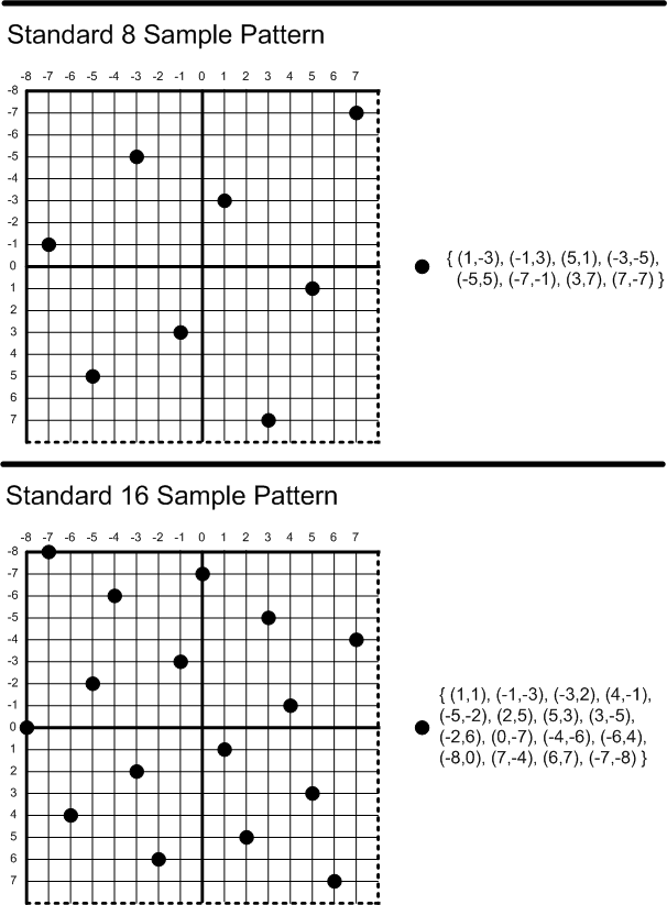
Some basic qualitative and quantitative tests were used to help select the sample patterns displayed. In particular halfplane discrepancy – the error between analytic coverage and sample based coverage – seems to be useful. Surprisingly the total L2 error (squared error over all edges through a pixel) was not that useful alone, but the worst case (L-inf) error over all halfplanes (single worst edge), the worst case orientation (orientation with largest squared error as a plane sweeps through the pixel) and the variance (combined with total L2) seem to be reasonable indicators. The orientation dependent contrast sensitivity function was also looked at (in the context of total L2), but only a crude approximation and fairly briefly.
At the time of design if was only possible to place samples on a sub-pixel grid limited to 16 horizontal and vertical divisions. Since it is undesirable for a sample pattern to have multiple samples line up vertically or horizontally, the definition of standard patterns for sample counts above 16 samples was postponed until the sub-pixel grid can be finer.
The standard center sample patterns (D3D11_CENTER_MULTISAMPLE_PATTERN) that have more than one sample overlapping at the center of the pixel have a couple of usage restrictions:
D3D11 requires support for 1x(trivial), 4x and 8x MSAA, with at minimum support for the standard patterns for these MSAA counts. At 4x MSAA, all output (RenderTarget/DepthStencil-able) formats must be supported. At 8x MSAA, only output formats with less than 128 bits per sample must be supported. Support for 128+ bits per sample formats with 8x MSAA is optional. Other MSAA counts and patterns are optional as before.
For D3D10.1 hardware, the requirements were as follows: D3D10.1 required support for 4x MSAA with at minimum support for the standard 4x MSAA pattern. At 4x MSAA, only output formats with less than 64 bits per sample must be supported. Support for 64+ bits per sample formats with 4x MSAA is optional.
Section Contents
(back to chapter)
19.3.1 Overview
19.3.2 RGBE Floating Point Format: DXGI_FORMAT_R9G9B9E5_SHAREDEXP
D3D11.3 supports a couple of high dynamic range pixel formats. This section defines these formats.
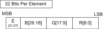
A color is represented by 3 mantissas and an exponent as follows:
For each component in {R,G,B}, the value "v" of the component is:
v = (0.frac)*2(e-15)
This format cannot be a RenderTarget.
float scale = 2(float)E[31:27] - 15
float r = (float)(0.R[8:0])*scale
float g = (float)(0.G[17:9])*scale
float b = (float)(0.B[26:18])*scale
float a = 1.0f

Example: 32-bit value 0x999320c8
R = 011001000 = 0.390625f
G = 110010000 = 0.78125f
B = 001100100 = 0.1953125f
E = 10011 = 19.f

scale = 219 - 15 = 16.f

Resulting rgba vector:
r = 0.390625*16 = 6.25
g = 0.78125*16 = 12.5
b = 0.1953125*16 = 3.125
a = 1.0
Due to the lack of an implied 1, all RGBE colors can be represented by legal 16-bit floating point numbers. In particular, values with an unbiased exponent of 31 may not be treated as INF or NAN.
Note that this conversion to RGBE is never perfomed in D3D11.3 (i.e. hardware). This conversion is listed merely for completeness; and might be used by a software encoder.
    sharedExponent =  max(redExponent, greenExponent, blueExponent); [note, these are treated as unbiased]

    foreach component {R,G,B}:

        convert fraction to 9 bits
        output fraction = (converted fraction) >> (sharedExponent - componentExponent))

        bias exponent (add 15) and store
This format consists of 3 independent, reduced-mantissa floating point channels. See the 11-bit and 10-bit Floating Point(3.1.6) section for a description of the mechanics of these reduced precision numbers.
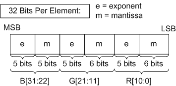
The sub-sampled formats (such as R8G8_B8G8) are reconstructed via replication to per-pixel RGB values prior to use.
The G component is taken from the currently addressed pixel value. The R component is taken from the current pixel value for even x resource addresses, and from the previous ('-1'th) x dimension pixel value for odd x resource addresses. The B component is taken from the next ('+1'th) x dimension pixel value for even x resource addresses, and from the current pixel value for odd x resource addresses.
Resources in these formats are required to be a multiple of 2 in the x dimension, rounding up to an x dimension of 2 for the smallest mipmap levels. For mipmaps, the sizing and sampling hardware behavior is similar to Block Compressed Formats(19.5), where the top level map must be a multiple of 2 size in the x dimension, and for smaller maps the virtual x dimension size may be odd while the physical size is always even.
The regions being sourced and modified by the Resource Manipulation(5.6) operations are required to be a multiple of 2 in the x dimension.
Section Contents
(back to chapter)
19.5.1 Overview
19.5.2 Error Tolerance
19.5.3 Promotion to wider UNORM values:
19.5.4 Promotion to wider SNORM values:
19.5.5 Memory Layout
19.5.6 BC1{U|G}: 2(+2 Derived) Opaque Colors or 2(+1 Derived) Opaque Colors + Transparent Black
19.5.7 BC2{U|G}: 2(+2 Derived) Colors, 16 Alphas
19.5.8 BC3{U|G}: 2(+2 Derived) Colors, 2(+6 Derived) Alphas or 2(+4 Derived + Transparent + Opaque) Alphas
19.5.9 BC4U: 2(+6 Derived) Single Component UNORM Values
19.5.10 BC4S: 2(+6 Derived) Single Component SNORM Values
19.5.11 BC5U: 2(+6 Derived) Dual (Independent) Component UNORM Values
19.5.12 BC5S: 2(+6 Derived) Dual (Independent) Component SNORM Values
19.5.13 BC6H / DXGI_FORMAT_BC6H
This section describes various block-based compression formats. A surface is divided into 4x4 texel blocks, and each 16-texel block is encoded in a particular manner as an atomic unit. Each distinct encoding method is given a unique format name (identified by a four-character code and matching DXGI_FORMAT_BC* name).
Block Compressed formats can be used for Texture2D (including arrays), Texture3D or TextureCube (including arrays), including mipmap surfaces in these Resources.
BC format surfaces are always multiples of full blocks, each block representing 4x4 pixels. For mipmaps, the top level map is required to be a multiple of 4 size in all dimensions. The sizes for the lower level maps are computed as they are for all mipmapped surfaces, and thus may not be a multiple of 4, for example a top level map of 20 results in a second level map size of 10. For these cases, there is a differing 'physical' size and a 'virtual' size. The virtual size is that computed for each mip level without adjustment, which is 10 for the example. The physical size is the virtual size rounded up to the next multiple of 4, which is 12 for the example, and this represents the actual memory size. The sampling hardware will apply texture address processing based on the virtual size (using, for example, border color if specified for accesses beyond 10), and thus for the example case will not access the 11th and 12th row of the resource. So for mipmap chains when an axis becomes < 4 in size, only texels 'a','b','e','f' (see diagram below) are used for a 2x2 map, and texel 'a' is used for 1x1. Note that this is similar to, but distinct from, the surface pitch, which can encompass additional padding beyond the physical surface size.
The regions of BC formats being sourced and/or modified by the Resource Manipulation(5.6) operations are required to be a multiple of 4.
Decompression always occurs before filtering.
Valid implementations of BC formats other than BC6H and BC7 may optionally promote or do round-to-nearest division, so long as they meet the following equation for all channels of all texels:
| generated - reference | < absolute_error + 0.03
                            *MAX( | endpoint_0 - endpoint_1 |,
                                  | endpoint_0_promoted - endpoint_1_promoted | )
absolute_error is defined in the description of each format.
endpoint_0, endpoint_1, and their promoted counterparts have been converted to float from either UNORM or SNORM as specified in the Integer Conversion(3.2.3) rules. Values that the reference decodes to 0.0, 1.0 or -1.0 must always be exact.
For BC6H and BC7, decompression hardware is required to be bit accurate; the hardware must give results that are identical to the decoder described in this specification.
Promotion is defined to utilize MSB extension to define the new LSBs as follows.
int UNORMPromote(int input, int baseBitCount, int targetBitCount)
{
    int numBits = targetBitCount-baseBitCount;
    input <<= numBits;
    int outval = input;
    do {
        input >>= baseBitCount;
        outval |= input;
        numbits -= baseBitCount;
    } while(numBits > 0);
    return outval;
}
int SNORMPromote(int input, int base, int target)
{
    if (input<0)
        return -UNORMPromote(-input, baseBitCount-1, targetBitCount-1);
    return UNORMPromote(input, baseBitCount-1, targetBitCount-1);
}
The following diagram depicts the overall layout of data in a Block Compressed surface. After that, the per-block memory encoding for each BC* format is individually illustrated.
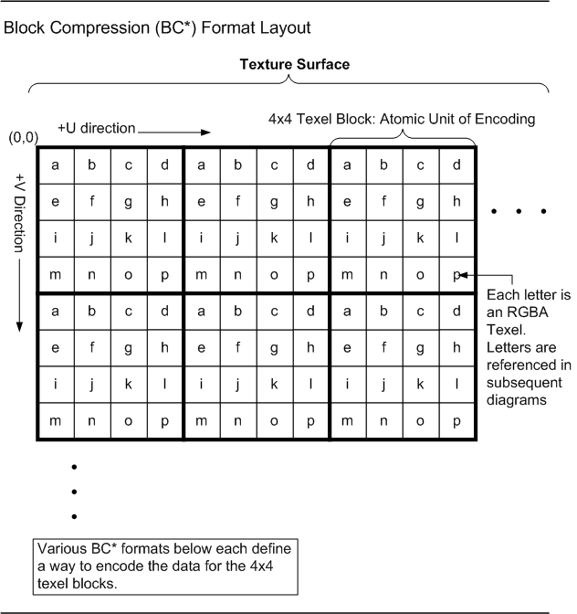
BC1U/BC1G (DXGI_FORMAT_BC1_UNORM[_SRGB]) is known in older APIs as DXGI_FORMAT_DXT1.

color_0_p = promoteToUNORM8(color_0)
color_1_p = promoteToUNORM8(color_1)
if (color_0 > color_1) // unsigned compare
{
    // Four-color block:
    color_2 = (2 * color_0_p + color_1_p) / 3;
    color_3 = (color_0_p + 2 * color_1_p) / 3;
    alpha_3 = 1.0f
} else {
    // Three-color block:
    color_2 = (color_0_p + color_1_p) / 2;
    color_3 = (0.0f,0.0f,0.0f); alpha_3 = 0.0f
}
// color_*: Actually 3 independent calculations for R,G,B.

// The following 2-bit codes select
// a UNORM8 color for each texel:
// (MSB)00(LSB) = color_0_p, alpha=1.0f
//      01      = color_1_p, alpha=1.0f
//      10      = color_2,   alpha=1.0f
//      11      = color_3,   alpha=alpha_3
BC1G / DXGI_FORMAT_BC1_UNORM_SRGB:
Same as BC1U, but colors are in sRGB space, linearized pre-filter on read. sRGB conversion should occur the same as with uncompressed UNORM8 formats. If an implementation provides more precise palette entries than it can linearize, it may have up to 1 UNORM8 ULP error in conversion on input to linearization.
BC2U/BC2G (DXGI_FORMAT_BC2_UNORM[_SRGB]) is known in older APIs as both DXGI_FORMAT_DXT2 and DXGI_FORMAT_DXT3, where DXT2 is the same as DXT3 except whether or not the color data is assumed to be pre-multiplied by alpha. This pre-multiplied alpha distinction is meaningless to the graphics system, as the hardware doesn't care about pre-multiplied alpha. It is up to application to change Shader code if appropriate for handling the distinction. Therefore, the use of separate format names to distinguish pre-multiplied alpha vs. non-pre-multiplied alpha was removed for D3D11.3. If applications want to keep track of whether a format contains pre-multiplied alpha, that can be done by other means (such as storing private data for resources), which would work equally well for all formats, and not just the Block Compression formats. Note that in contrast to the pre-multiplied alpha property, the distinction of whether the resource contains SRGB data or not is indeed important for hardware, so in D3D11.3 separate formats are used for linear vs SRGB data where appropriate.
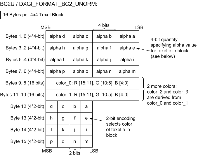
// Four-color block: derive the other two colors
color_0_p = promoteToUNORM8(color_0)
color_1_p = promoteToUNORM8(color_1)
color_2 = (2 * color_0 + color_1) / 3;
color_3 = (color_0 + 2 * color_1) / 3;
// color_*: Actually 3 independent calculations for R,G,B.

// The following 2-bit codes select
// a UNORM8 color for each texel:
// (MSB)00(LSB) = color_0_p,
//      01      = color_1_p,
//      10      = color_2,
//      11      = color_3

// Derive alpha value for texel t:
alpha = alpha[t]/15.0f
BC2G / DXGI_FORMAT_BC2_UNORM_SRGB:
BC3U/BC3G (DXGI_FORMAT_BC3_UNORM[_SRGB]) is known in older APIs as both DXGI_FORMAT_DXT4 and DXGI_FORMAT_DXT5, where DXT4 is the same as DXT5 except whether or not the color data is assumed to be pre-multiplied by alpha. This pre-multiplied alpha distinction is meaningless to the graphics system, as the hardware doesn't care about pre-multiplied alpha. It is up to the application to change Shader code if appropriate for handling the distinction. Therefore, the use of separate format names to distinguish pre-multiplied alpha vs. non-pre-multiplied alpha was removed for D3D11.3. If applications want to keep track of whether a format contains pre-multiplied alpha, that can be done by other means (such as storing private data for resources), which would work equally well for all formats, and not just the Block Compression formats. Note that in contrast to the pre-multiplied alpha property, the distinction of whether the resource contains SRGB data or not is indeed important for hardware, so in D3D11.3 separate format names distinguish linear vs SRGB data where appropriate.
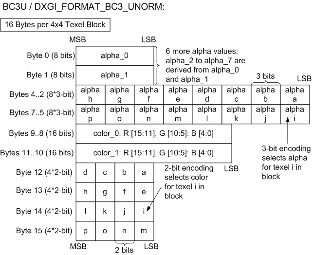
// Four-color block: derive the other two colors
color_0_p = promoteToUNORM8(color_0)
color_1_p = promoteToUNORM8(color_1)
color_2 = (2 * color_0 + color_1) / 3;
color_3 = (color_0 + 2 * color_1) / 3;
// color_*: Actually 3 independent calculations for R,G,B.

// The following 2-bit codes select
// a UNORM8 color for each texel:
// (MSB)00(LSB) = color_0_p,
//      01      = color_1_p,
//      10      = color_2,
//      11      = color_3
BC3G / DXGI_FORMAT_BC3_UNORM_SRGB:
This general purpose format compresses single-component UNORM data.
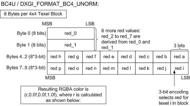
redf_0 = UNORM8ToFloat(red_0)
redf_1 = UNORM8ToFloat(red_1)
if (red_0 > red_1) // unsigned compare
{
    // 8-red block
    // Bit code 000 = redf_0, 001 = redf_1, others are interpolated.
    redf_2 = (6 * redf_0 + 1 * redf_1) / 7.0f;   // bit code 010
    redf_3 = (5 * redf_0 + 2 * redf_1) / 7.0f;   // bit code 011
    redf_4 = (4 * redf_0 + 3 * redf_1) / 7.0f;   // bit code 100
    redf_5 = (3 * redf_0 + 4 * redf_1) / 7.0f;   // bit code 101
    redf_6 = (2 * redf_0 + 5 * redf_1) / 7.0f;   // bit code 110
    redf_7 = (1 * redf_0 + 6 * redf_1) / 7.0f;   // bit code 111
} else {
    // 6-red block.
    // Bit code 000 = redf_0, 001 = redf_1, others are interpolated.
    redf_2 = (4 * redf_0 + 1 * redf_1) / 5.0f; // bit code 010
    redf_3 = (3 * redf_0 + 2 * redf_1) / 5.0f; // bit code 011
    redf_4 = (2 * redf_0 + 3 * redf_1) / 5.0f; // bit code 100
    redf_5 = (1 * redf_0 + 4 * redf_1) / 5.0f; // bit code 101
    redf_6 = 0.0f;                             // bit code 110
    redf_7 = 1.0f;                             // bit code 111
}
This general purpose format compresses single-component SNORM data.
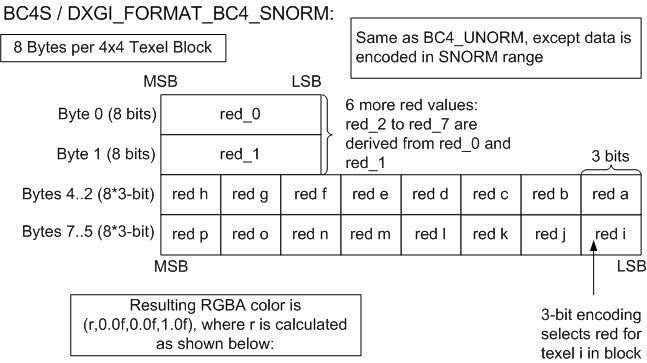
redf_0 = SNORM8ToFloat(red_0)
redf_1 = SNORM8ToFloat(red_1)
if (red_0 > red_1) // signed compare.
{
    // 8-red block
    // Bit code 000 = redf_0, 001 = redf_1, others are interpolated.
    redf_2 = (6 * redf_0 + 1 * redf_1) / 7.0f;   // bit code 010
    redf_3 = (5 * redf_0 + 2 * redf_1) / 7.0f;   // bit code 011
    redf_4 = (4 * redf_0 + 3 * redf_1) / 7.0f;   // bit code 100
    redf_5 = (3 * redf_0 + 4 * redf_1) / 7.0f;   // bit code 101
    redf_6 = (2 * redf_0 + 5 * redf_1) / 7.0f;   // bit code 110
    redf_7 = (1 * redf_0 + 6 * redf_1) / 7.0f;   // bit code 111
} else {
    // 6-red block.
    // Bit code 000 = redf_0, 001 = redf_1, others are interpolated.
    redf_2 = (4 * redf_0 + 1 * redf_1) / 5.0f; // bit code 010
    redf_3 = (3 * redf_0 + 2 * redf_1) / 5.0f; // bit code 011
    redf_4 = (2 * redf_0 + 3 * redf_1) / 5.0f; // bit code 100
    redf_5 = (1 * redf_0 + 4 * redf_1) / 5.0f; // bit code 101
    redf_6 = -1.0f;                            // bit code 110
    redf_7 = 1.0f;                             // bit code 111
}
This general purpose format compresses dual-component UNORM data.
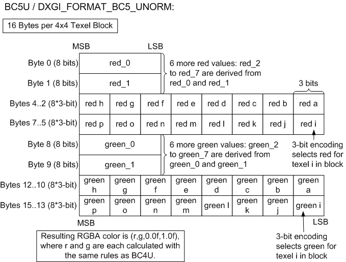
absolute_error = 1.0/65535.0
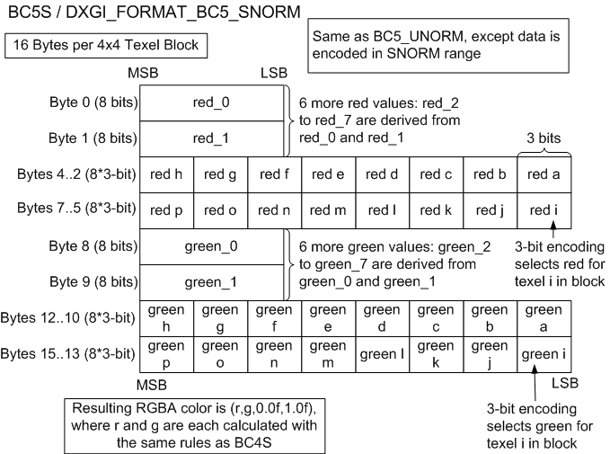
absolute_error = 1.0/32767.0
The following DXGI_FORMATs are in this category: DXGI_FORMAT_BC6H_TYPELESS, DXGI_FORMAT_BC6H_UF16, and DXGI_FORMAT_BC6H_SF16.
The BC6H format can be used for Texture2D (including arrays), Texture3D or TextureCube (incl. arrays). All of these uses include mipmap surfaces in these resources.
BC6H uses a fixed block size of 16 bytes and a fixed tile size of 4x4 pixels. Just as with previous BC formats, images larger than BC6H's tile size are compressed using multiple blocks. The same addressing identity also applies to three-dimensional images as well as mip-maps, cubemaps, and texture arrays.
BC6H compresses three-channel images that have high dynamic range greater than 8 bits per channel. The supported per-channel formats are:
All image tiles must be of the same format.
BC6H supports floating point denorms, but INF and NaN are not supported. The exception is the signed mode of BC6H, which can represent ±INF. While this ±INF "support" was unintentional, it is baked into the format. So it is valid for encoders to intentionally use ±INF, but they also have the option to clamp during encode to avoid it. In general, faced with ±INF or NaN input data to deal with, encoders are loosely encouraged to clamp ±INFs to the corresponding maximum non-INF representable value, and map NaN to 0 prior to compression.
BC6H does not store any alpha data.
The BC6H decoder decompresses to the specified format prior to filtering.
BC6H decompression hardware is required to be bit accurate; the hardware must give results that are identical to the decoder described in this specification.
A BC6H block consists of mode bits, compressed endpoints, sometimes a partition index, and compressed indices.
BC6H uses 14 different modes.
BC6H stores endpoint colors as a red, green, and blue (RGB) triplet, defining a palette of colors on an approximate line between two endpoints. Depending upon the mode, a tile is divided into one or two regions, each having its own pair of endpoints. BC6H stores one palette index per pixel.
In the two region case (hereafter referred to as TWO), there are 32 possible partitions. (The one region case will hereafter be referred to as ONE.)
The pseudocode below outlines the steps to decompress the pixel at (x,y) given the 16-byte BC6H block.
decompress(x, y, block)
{
    mode = extract_mode(block);
    endpoints;
    index;

    if(mode.type == ONE)
    {
        endpoints = extract_compressed_endpoints(mode, block);
        index = extract_index_ONE(x, y, block);
    }
    else //mode.type == TWO
    {
        partition = extract_partition(block);
        region = get_region(partition, x, y);
        endpoints = extract_compressed_endpoints(mode, region, block);
        index = extract_index_TWO(x, y, partition, block);
    }

    unquantize(endpoints);
    color = interpolate(index, endpoints);
    finish_unquantize(color);
}
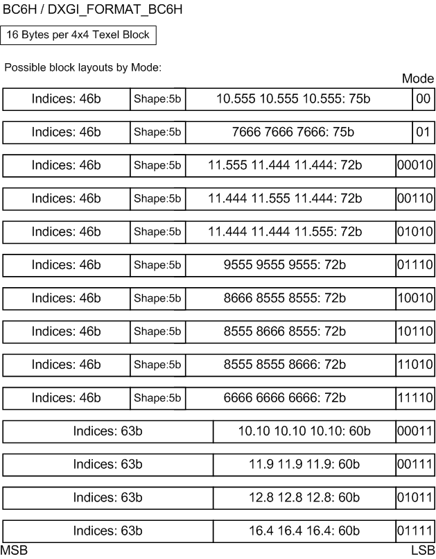
The diagram above shows the 14 possible formats for BC6H blocks. The formats can be uniquely identified by the Mode bits.The first ten modes are used by TWO, and the mode field can be either 2 or 5 bits long. These blocks also have fields for the compressed endpoints (75 bits), partition (5 bits), and indices (46 bits). As an example, the code "11.555 11.444 11.444" indicates both the precision of the red, green, and blue endpoints stored (11), as well as the number of bits used to store the delta values for the transformed endpoints (5, 4, and 4 bits for red, green, and blue, respectively, for 3 delta values.) The "6666" mode handles the case when the endpoints cannot be transformed; only the quantized endpoints are stored.
The last four modes are used by ONE, and the mode field is 5 bits. These blocks have fields for the endpoints (60 bits) and indices (63 bits). For ONE, the example endpoint code "11.9 11.9 11.9" indicates both the precision of the red, green, and blue endpoints stored (11), as well as the number of bits used to store the delta values for the transformed endpoints (9 bits for red, green, and blue, respectively, for 1 delta value.) The "10.10" mode handles the case when the endpoints cannot be transformed; only the quantized endpoints are stored.
Modes 10011, 10111, 11011, and 11111 are reserved and should not be used by the encoder. If hardware is given these modes, the resulting decompressed block must contain zeroes in all channels except the alpha channel. For BC6H, the alpha channel should always return 1.0 regardless of the mode.
There are 32 partition sets for TWO, which are defined by Table 1 below. Each 4x4 block represents a single shape. Note that this table is equivalent to the first 32 entries of BC7's 2 subset partition table.
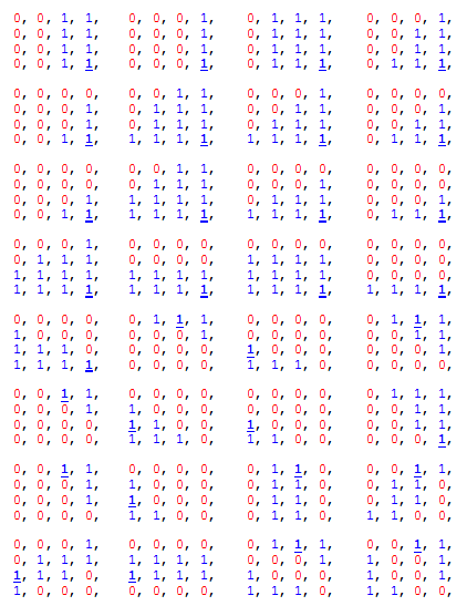
In the table of partitions above, the bolded and underlined entry is the location of the fix-up index for subset 1 which is specified with one less bit. The fix-up index for subset 0 is always index 0 (i.e. the partitioning is arranged so that index 0 is always in subset 0). Partition order goes from top-left to bottom right, walking left-to-right, then top-to-bottom.
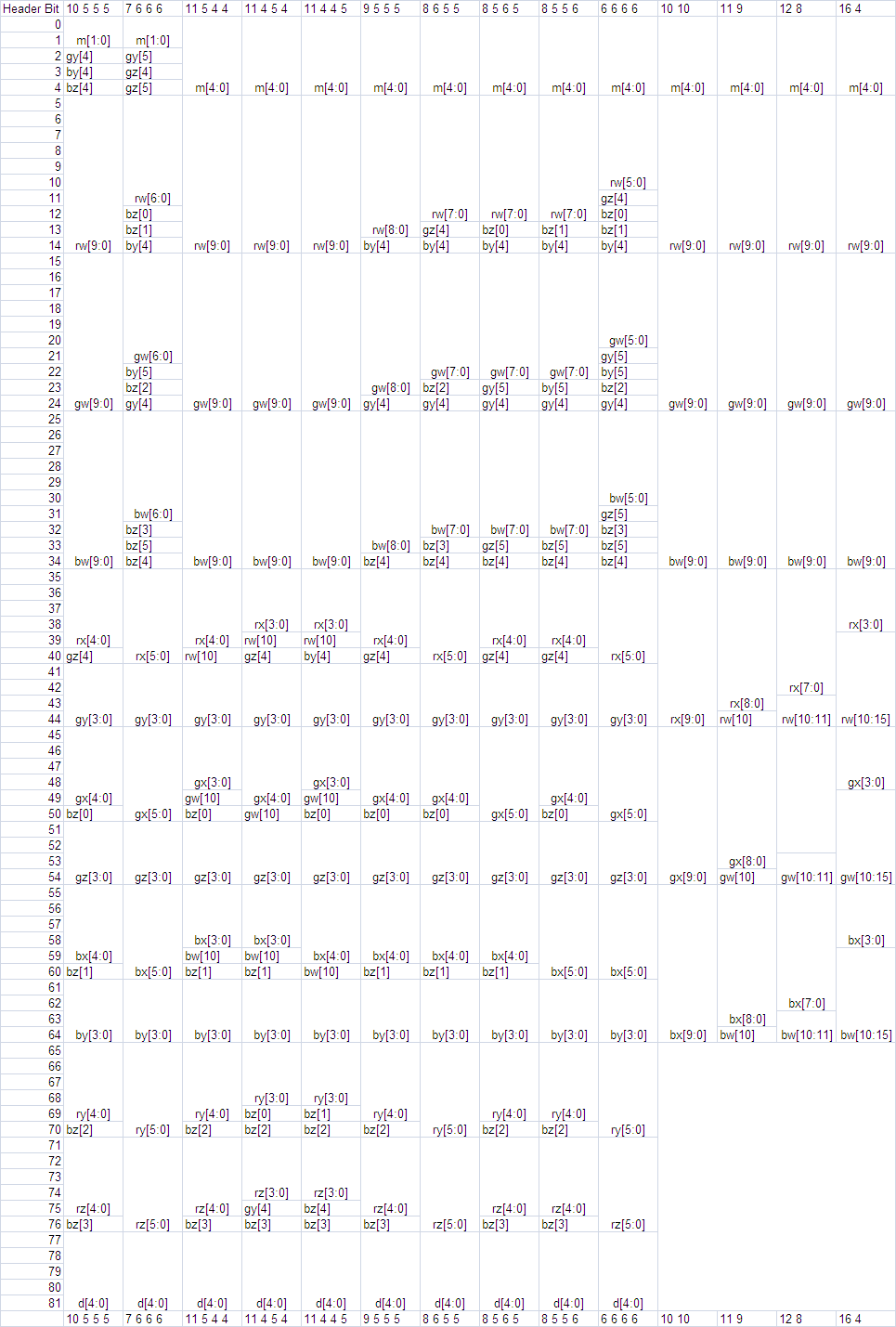
Table 2 above shows the bit fields for the packed compressed endpoints as a function of the endpoint format. This takes up 82 bits for TWO and 65 bits for ONE. As an example, the first 5 bits of the header for the last encoding above (i.e. the right-most column) are bits m[4:0], the next 10 bits of the header are the bits rw[9:0], and so forth.
The field names are defined by the following table
FIELD   VARIABLE    FIELD   VARIABLE        FIELD    VARIABLE        FIELD    VARIABLE
m       mode        rw        endpt[0].A[0]   gw          endpt[0].A[1]        bw          endpt[0].A[2]
d       shape index rx        endpt[0].B[0]   gx          endpt[0].B[1]        bx          endpt[0].B[2]
                    ry        endpt[1].A[0]   gy          endpt[1].A[1]        by            endpt[1].A[2]
                    rz        endpt[1].B[0]   gz          endpt[1].B[1]        bz            endpt[1].B[2]
Endpt[i] refers to the 0th or 1st pair of endpoints. A is one endpoint of 3 channels A[0]..A[2], and similarly B is the other endpoint of 3 channels.
For TWO, there are four endpoint values to possibly sign-extend. endpts[0].A is signed only if the format is a signed format. The other endpoints are signed only if the endpoint was transformed, or the format is a signed format.
static void sign_extend(Pattern &p, IntEndpts endpts[NREGIONS_TWO])
{
    for (int i=0; i<NCHANNELS; ++i)
    {
    if (BC6H::FORMAT == SIGNED_F16)
        endpts[0].A[i] = SIGN_EXTEND(endpts[0].A[i], p.chan[i].prec);
    if (p.transformed || BC6H::FORMAT == SIGNED_F16)
    {
        endpts[0].B[i] = SIGN_EXTEND(endpts[0].B[i], p.chan[i].delta[0]);
        endpts[1].A[i] = SIGN_EXTEND(endpts[1].A[i], p.chan[i].delta[1]);
        endpts[1].B[i] = SIGN_EXTEND(endpts[1].B[i], p.chan[i].delta[2]);
    }
    }
}
The code for ONE is similar and just removes endpts[1].
static void sign_extend(Pattern &p, IntEndpts endpts[NREGIONS_ONE])
{
    for (int i=0; i<NCHANNELS; ++i)
    {
    if (BC6H::FORMAT == SIGNED_F16)
        endpts[0].A[i] = SIGN_EXTEND(endpts[0].A[i], p.chan[i].prec);
    if (p.transformed || BC6H::FORMAT == SIGNED_F16)
        endpts[0].B[i] = SIGN_EXTEND(endpts[0].B[i], p.chan[i].delta[0]);
    }
}
There is also sign extending for signed formats in the transform_inverse step shown below.
For TWO, the transform applies the inverse of the difference encoding, adding the base value at endpt[0].A to the other three entries, for a total of 9 adds. In the diagram below, the base value is represented as A0 and has the highest precision. A1, B0, and B1 are all deltas off of the anchor value, and these deltas are represented with lower precision. (A0 corresponds to endpt[0].A, B0 to endpt[0].B, and similarly for A1 and B1.)
![]()
The ONE case is similar, except there is only 1 delta offset, and thus a total of only 3 adds.
The decompressor should ensure that the results of the inverse transform will not overflow the precision of endpt[0].A. In the case of overflow, the values resulting from the inverse transform should wrap within the same number of bits. If the precision of A0 is 'p' bits, the transform is:
B0 = (B0+A0) & ((1 << p) - 1)
and similarly for the other cases.
For signed formats the results of the delta arithmetic must be sign extended as well. If the sign extend operation is thought of as extending both signs: 1 (negative) and 0 (positive), then the sign extending of 0 takes care of the clamp above. Or equivalently after the clamp above, only 1 (negative) needs to be extended.
Given the uncompressed endpoints, the next steps are to perform an initial unquantization step, interpolate, and then do a final unquantize. Seperating the unquantize step into two substeps reduces the number of multiplications required compared to doing a full unquantize before interpolating.
The code below illustrates the unquantizing process to retrieve estimates of the original 16 bit value, and then using the specified weights to get 6 additional values into the palette. The same operation is performed on each channel.
Since the full range of the unquantize function is -32768 to 65535, the interpolator is implemented using 17 bit signed arithmetic.
After interpolation, the values are passed to the finish_unquantize function, which applies the final scaling.
All hardware decompressors are required to return bit accurate results with this functon.
int aWeight3[] = {0, 9, 18, 27, 37, 46, 55, 64};
int aWeight4[] = {0, 4, 9, 13, 17, 21, 26, 30, 34, 38, 43, 47, 51, 55, 60, 64};

// c1, c2: endpoints of a component
void generate_palette_unquantized(UINT8 uNumIndices, int c1, int c2, int prec, UINT16 palette[NINDICES])
{
    int* aWeights;
    if(uNumIndices == 8)
        aWeights = aWeight3;
    else  // uNumIndices == 16
        aWeights = aWeight4;

    int a = unquantize(c1, prec);
    int b = unquantize(c2, prec);

    // interpolate
    for(int i = 0; i < uNumIndices; ++i)
        palette[i] = finish_unquantize((a * (64 - aWeights[i]) + b * aWeights[i] + 32) >> 6);
}
The following describes how unquantize works. For UF16, 'comp' is unquantized into 0x0000 ~ 0xFFFF range to maximize the usage of bits.
int unquantize(int comp, int uBitsPerComp)
{
    int unq, s = 0;
    switch(BC6H::FORMAT)
    {
    case UNSIGNED_F16:
        if(uBitsPerComp >= 15)
            unq = comp;
        else if(comp == 0)
            unq = 0;
        else if(comp == ((1 << uBitsPerComp) - 1))
            unq = 0xFFFF;
        else
            unq = ((comp << 16) + 0x8000) >> uBitsPerComp;
        break;

    case SIGNED_F16:
        if(uBitsPerComp >= 16)
            unq = comp;
        else
        {
            if(comp < 0)
            {
                s = 1;
                comp = -comp;
            }

            if(comp == 0)
                unq = 0;
            else if(comp >= ((1 << (uBitsPerComp - 1)) - 1))
                unq = 0x7FFF;
            else
                unq = ((comp << 15) + 0x4000) >> (uBitsPerComp-1);

            if(s)
                unq = -unq;
        }
        break;
    }
    return unq;
}
finish_unquantize is called after palette interpolation. The unquantize function postpones the scaling by 31/32 for signed, 31/64 for unsigned. This is needed to get the final value into valid half range(-0x7BFF ~ 0x7BFF) after the palette interpolation is completed to reduce the number of necessary multiplications. finish_unquantize applies the final scaling and returns an unsigned short value that gets reinterpreted into half.
unsigned short finish_unquantize(int comp)
{
    if(BC6H::FORMAT == UNSIGNED_F16)
    {
        comp = (comp * 31) >> 6;                                         // scale the magnitude by 31/64
        return (unsigned short) comp;
    }
    else // (BC6H::FORMAT == SIGNED_F16)
    {
        comp = (comp < 0) ? -(((-comp) * 31) >> 5) : (comp * 31) >> 5;   // scale the magnitude by 31/32
        int s = 0;
        if(comp < 0)
        {
            s = 0x8000;
            comp = -comp;
        }
        return (unsigned short) (s | comp);
    }
}
The following DXGI_FORMATs are in this category: DXGI_FORMAT_BC7_TYPELESS, DXGI_FORMAT_BC7_UNORM, and DXGI_FORMAT_BC7_UNORM_SRGB
The BC7 format can be used for Texture2D (including arrays), Texture3D or TextureCube (incl. arrays). All of these uses include mipmap surfaces in these resources.
BC7 uses a fixed block size of 16 bytes and a fixed tile size of 4x4 pixels. As with other BC formats, images larger than BC7's tile size are compressed using multiple blocks. The same addressing identity also applies to three-dimensional images as well as mip-maps, cubemaps, and texture arrays.
BC7 compresses both three-channel and four-channel fixed-point data images. Typically source data will be 8-bits per component fixed point, although the format is capable of encoding source data with higher bits per component. All image tiles must be of the same format.
The BC7 decoder decompresses to the specified format prior to filtering.
BC7 decompression hardware is required to be bit accurate; the hardware must give results that are identical to the decoder described in this specification.
A BC7 block can take one of 8 modes, and the block mode is always stored in the LSBs of the 128-bit block. The block mode is encoded by zero or more "0"'s followed by a "1". This mode string starts from the block LSB.
A BC7 block may contain multiple endpoint pairs. For the purposes of this document, the set of indices that correspond to an endpoint pair may be referred to as a subset.
In some block modes the endpoint representation is encoded in a form that for the purposes of this document will be called RGBP – in these cases the P bit represents a shared LSB for the components of the endpoint. For example, if the endpoint representation for the format was RGBP 5.5.5.1 then the endpoint would be interpreted as an RGB 6.6.6 value, with the LSB of each component being taken from the state of the P bit. If the representation was RGBAP 5.5.5.5.1 then the endpoint would be interpreted as an RGBA 6.6.6.6 value. Depending on the block mode the shared LSB may either be specified for both endpoints of a subset individually (2 P-bits per subset), or shared between the endpoints of the subset (1 P-bit per subset)
For BC7 blocks that do not explicity encode alpha, a BC7 block consists of mode bits, partition bits, compressed endpoints, sometimes a P-bit, and compressed indices. In these blocks the endpoints have an R.G.B-only representation and alpha is decoded as 1.0 for all texels
For BC7 blocks that encode combined color and alpha, a block consists of mode bits, sometimes partition bits, compressed endpoints, and compressed indices. In these blocks the endpoint color values are specified in an R.G.B.A format, and alpha values are interpolated along with the color values.
For BC7 blocks that separately encode color and alpha, a block consists of mode bits, rotation bits, sometimes an index selector bit, compressed endpoints, and compressed indices. These blocks effectively have a vector channel (R.G.B) and a scalar channel (A) separately encoded.
BC7 uses 8 different modes.
BC7 defines a palette of colors on an approximate line between two endpoints. The mode specifies the number of interpolating endpoint pairs per block. BC7 stores one palette index per pixel.
For each subset of indices that corresponds to a pair of endpoints, the encoder fixes the state of one bit of the compressed index data for that subset. This is done by choosing an endpoint order that allows the index for the designated fixup index to have 0 as its MSB, which can therefore be discarded saving one bit per subset. The indices with the "fix-up" bit are noted in the partition tables for 2 subsets(19.5.14.5) and 3 subsets(19.5.14.6) below. For block modes with only a single subset, the fix-up index is always index 0.
The pseudocode below outlines the steps to decompress the pixel at (x,y) given the 16-byte BC7 block.
decompress(x, y, block)
{
    mode = extract_mode(block);

    //decode partition data from explicit partition bits
    subset_index = 0;
    num_subsets = 1;

    if (mode.type == 0 OR == 1 OR == 2 OR == 3 OR == 7)
    {
        num_subsets = get_num_subsets(mode.type);
        partition_set_id = extract_partition_set_id(mode, block);
        subset_index = get_partition_index(num_subsets, partition_set_id, x, y);
    }

    //extract raw, compressed endpoint bits
    UINT8 endpoint_array[num_subsets][4] = extract_endpoints(mode, block);

    //decode endpoint color and alpha for each subset
    fully_decode_endpoints(endpoint_array, mode, block);

    //endpoints are now complete.
    UINT8 endpoint_start[4] = endpoint_array[2 * subset_index];
    UINT8 endpoint_end[4]   = endpoint_array[2 * subset_index + 1];

    //Determine the palette index for this pixel
    alpha_index     = get_alpha_index(block, mode, x, y);
    alpha_bitcount  = get_alpha_bitcount(block, mode);
    color_index     = get_color_index(block, mode, x, y);
    color_bitcount  = get_color_bitcount(block, mode);

    //determine output
    UINT8 output[4];
    output.rgb = interpolate(endpoint_start.rgb, endpoint_end.rgb, color_index, color_bitcount);
    output.a   = interpolate(endpoint_start.a,   endpoint_end.a,   alpha_index, alpha_bitcount);

    if (mode.type == 4 OR == 5)
    {
        //Decode the 2 color rotation bits as follows:
        // 00 - Block format is Scalar(A) Vector(RGB) - no swapping
        // 01 - Block format is Scalar(R) Vector(AGB) - swap A and R
        // 10 - Block format is Scalar(G) Vector(RAB) - swap A and G
        // 11 - Block format is Scalar(B) Vector(RGA) - swap A and B
        rotation = extract_rot_bits(mode, block);
        output = swap_channels(output, rotation);
    }

}
The pseudocode below outlines the steps to fully decode endpoint color and alpha for each subset given the 16-byte BC7 block.
fully_decode_endpoints(endpoint_array, mode, block)
{
    //first handle modes that have P-bits
    if (mode.type == 0 OR == 1 OR == 3 OR == 6 OR == 7)
    {
        for each endpoint i
        {
            //component-wise left-shift
            endpoint_array[i].rgba = endpoint_array[i].rgba << 1;
        }

        //if P-bit is shared
        if (mode.type == 1)
        {
            pbit_zero = extract_pbit_zero(mode, block);
            pbit_one = extract_pbit_one(mode, block);

            //rgb component-wise insert pbits
            endpoint_array[0].rgb |= pbit_zero;
            endpoint_array[1].rgb |= pbit_zero;
            endpoint_array[2].rgb |= pbit_one;
            endpoint_array[3].rgb |= pbit_one;
        }
        else //unique P-bit per endpoint
        {
            pbit_array = extract_pbit_array(mode, block);
            for each endpoint i
            {
                endpoint_array[i].rgba |= pbit_array[i];
            }
        }
    }

    for each endpoint i
    {
        // Color_component_precision & alpha_component_precision includes pbit
        // left shift endpoint components so that their MSB lies in bit 7
        endpoint_array[i].rgb = endpoint_array[i].rgb << (8 - color_component_precision(mode));
        endpoint_array[i].a = endpoint_array[i].a << (8 - alpha_component_precision(mode));

        // Replicate each component's MSB into the LSBs revealed by the left-shift operation above
        endpoint_array[i].rgb = endpoint_array[i].rgb | (endpoint_array[i].rgb >> color_component_precision(mode));
        endpoint_array[i].a = endpoint_array[i].a | (endpoint_array[i].a >> alpha_component_precision(mode));
    }

    //If this mode does not explicitly define the alpha component
    //set alpha equal to 1.0
    if (mode.type == 0 OR == 1 OR == 2 OR == 3)
    {
        for each endpoint i
        {
            endpoint_array[i].a = 255; //i.e. alpha = 1.0f
        }
    }
}
UINT16 aWeight2[] = {0, 21, 43, 64};
UINT16 aWeight3[] = {0, 9, 18, 27, 37, 46, 55, 64};
UINT16 aWeight4[] = {0, 4, 9, 13, 17, 21, 26, 30, 34, 38, 43, 47, 51, 55, 60, 64};

UINT8 interpolate(UINT8 e0, UINT8 e1, UINT8 index, UINT8 indexprecision)
{
    if(indexprecision == 2)
        return (UINT8) (((64 - aWeights2[index])*UINT16(e0) + aWeights2[index]*UINT16(e1) + 32) >> 6);
    else if(indexprecision == 3)
        return (UINT8) (((64 - aWeights3[index])*UINT16(e0) + aWeights3[index]*UINT16(e1) + 32) >> 6);
    else // indexprecision == 4
        return (UINT8) (((64 - aWeights4[index])*UINT16(e0) + aWeights4[index]*UINT16(e1) + 32) >> 6);
}
bitcount get_color_bitcount(block, mode)
{
    if (mode.type == 0 OR == 1)
        return 3;

    if (mode.type == 2 OR == 3 OR == 5 OR == 7)
        return 2;

    if (mode.type == 6)
        return 4;

    //Only remaining case is Mode 4 with 1-bit index selector
    idxMode = extract_idxMode(block);
    if (idxMode == 0)
        return 2;
    else
        return 3;
}
Below is a list of the 8 block modes and bit allocations for the 8 possible BC7 blocks. The colors for each subset within a block are represented using two explicit endpoint colors and a set of interpolated colors between them. Depending on the block's index precision, each subset may have 4, 8 or 16 possible colors.
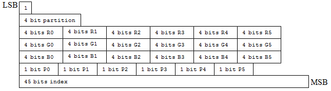
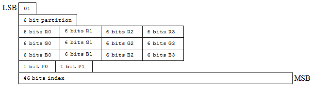
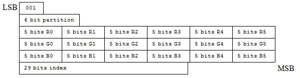
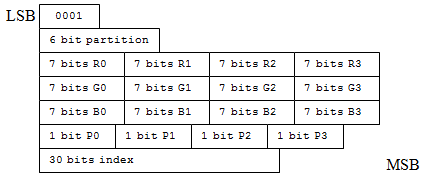
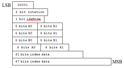
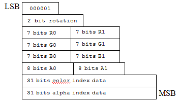
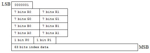
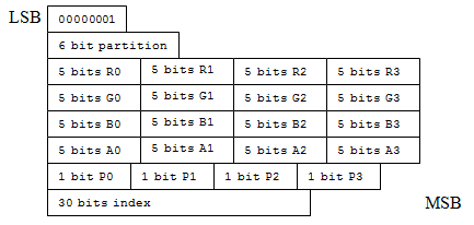
Mode 8 (LSB 0x00) is reserved and should not be used by the encoder. If this mode is given to the hardware, an all 0 block will be returned.
As previously discussed, in some block modes the endpoint representation is encoded in a form called RGBP – in these cases the P bit represents a shared LSB for the components of the endpoint. For example, if the endpoint representation for the format was RGBP 5.5.5.1 then the endpoint would be interpreted as an RGB 6.6.6 value, with the LSB of each component being taken from the state of the P bit. If the representation was RGBAP 5.5.5.5.1 then the endpoint would be interpreted as an RGBA 6.6.6.6 value. Depending on the block mode the shared LSB may either be specified for both endpoints of a subset individually (2 P-bits per subset), or shared between the endpoints of the subset (1 P-bit per subset)
In BC7, alpha can be encoded in several different ways:
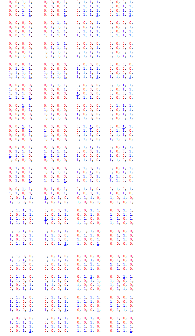
In the table of partitions above, the bolded, underlined entry is the location of the fix-up index for subset 1 which is specified with one less bit. The fix-up index for subset 0 is always index 0 (the partitioning is arranged so that index 0 is always in subset 0). Partition order goes from top-left to bottom right, walking left-to-right, then top-to-bottom.
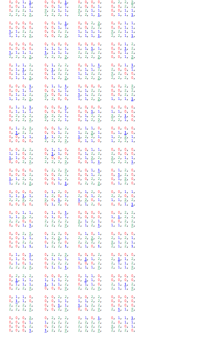
For this table of partitions, underneath the entry in each subset, printed in bold and underlined, is the location of the fix-up index which is specified with one less bit. Index 0 always contains the fixed index bit for subset 0. Partition order goes from top-left to bottom right, walking left-to-right, then top-to-bottom.
Three formats were added back to D3D11 which all existing GPUs support:
	1) DXGI_FORMAT_B5G6R5_UNORM
	2) DXGI_FORMAT_B5G5R5A1_UNORM
	3) DXGI_FORMAT_B4G4R4A4_UNORM
Required support for these formats depending on the hardware feature level:
| Capability | Feature Level 9_x | Feature Level 10.0 | Feature Level 10.1 | Feature Level 11+ |
| Typed Buffer | no | optional | optional | optional |
| Input Assembler Vertex Buffer | no | optional | optional | optional |
| Texture1D | no | req | req | req |
| Texture2D | req | req | req | req |
| Texture3D | no | req | req | req |
| TextureCube | req | req | req | req |
| Shader ld* | yes (point sample) | req | req | req |
| Shader sample* (with filtering) | req | req | req | req |
| Shader gather4 | no | no | no | req |
| Mipmap | req | req | req | req |
| Mipmap Auto-Generation | req for 565, no for 4444, 5551 |
req for 565, opt for 4444, 5551 |
req for 565, opt for 4444, 5551 |
req for 565, opt for 4444, 5551 |
| RenderTarget | req for 565, no for 4444, 5551 |
req for 565, opt for 4444, 5551 |
req for 565, opt for 4444, 5551 |
req for 565, opt for 4444, 5551 |
| Blendable RenderTarget | req for 565, no for 4444, 5551 |
req for 565, opt for 4444, 5551 |
req for 565, opt for 4444, 5551 |
req for 565, opt for 4444, 5551 |
| UAV Typed Store | no | no | no | optional |
| CPU Lockable | req | req | req | req |
| 4x MSAA | optional | optional | req for 565, opt for 4444, 5551 |
req for 565, opt for 4444, 5551 |
| 8x MSAA | optional | optional | optional | req for 565, opt for 4444, 5551 |
| Other MSAA Sample Count | optional | optional | optional | optional |
| Multisample Resolve | req (if MSAA supported) for 565, no for 4444, 5551 |
req (if MSAA supported) for 565, opt for 4444, 5551 |
req for 565, opt for 4444, 5551 |
req for 565, opt for 4444, 5551 |
| Multisample Load | no | req (if MSAA supported) for 565, opt for 4444, 5551) |
req for 565, opt for 4444, 5551 |
req for 565, opt for 4444, 5551 |
TODO
Chapter Contents
(back to top)
20.1 Pipeline statistics
20.2 Predicated Primitive Rendering
20.3 Query Manipulation
20.4 Query Type Descriptions
20.5 Performance Monitoring and Counters
Summary of Changes in this Chapter from D3D10 to D3D11.3
Back to all D3D10 to D3D11.3 changes.(25.2)
There exists the need to retrieve other data from the graphics accelerator, other than an output RenderTarget or output vertex buffer. Considering the graphics accelerator executes in parallel with the CPU, an API is necessary to expose the asynchronous nature of communication with the graphics accelerator efficiently. As a degenerate case, any data retrieval which needs to occur in a synchronous fashion can use the same API.
The basic resource related to the asynchronous notification API is the Query. Each Query object instance will be in one of three states: "signaled", "issued", and "building". Transitions to "building" and "issued" are achieved by the application with the use of the Issue(20.3.4) command. Transitions back to the "signaled" state are detected by the driver during the GetData(20.3.5) command. When the Query is in the "signaled" state, the data is available to pass back to the application.
Well-defined statistics for the Pipeline stages will be continuously calculated throughout the usage of the graphics accelerator. This typically indicates the need for hardware counters for each stage of the Pipeline. Such counters would be associated with the graphics context, so they require the ability to be context switched. Typically, drivers use the standard graphics Pipeline available on the graphics accelerator in order to implement some sort of functionality. For example, a Blt may actually be implemented as a textured quad rendering. In such a case, the graphics accelerator should not calculate statistics for such an operation. For example, such an emulated Blt operation should not appear to draw 2 triangles. This indicates the graphics accelerator needs to be able to toggle actual statistics calculation in an efficient manner. Most important, the graphics Pipeline should run at the same speed regardless of whether statistics are calculated or not; as the hardware counters will be expected to always be tabulating (except as previously mentioned, where the tabulation should be muted when performing emulation). The Pipeline statistics will be collected through the asynchronous notification mechanism. Note that D3D11_QUERY_OCCLUSION and D3D11_QUERY_SO_STATISTICS are considered to be well-defined Pipeline statistics, even though it is kept separate from D3D11_QUERY_DATA_PIPELINE_STATISTICS.
Rendering and draw operations are able to be predicated from the command stream, including Clear, UpdateSubresourceUP, CopySubresourceRegion, CopyResource. During Query creation, the Predicate Query is specified as to whether future predication must be guaranteed to execute by the presence of a flag. So, there are guaranteed predicates and separate predication hints. Allowing a guaranteed predicated rendering operation to proceed because of timing issues is unacceptable. However, a predicated rendering operation can proceed because of timing issues if a predication hint is used. In addition, hints will not be able to return any data to the application, like other queries and predicates will. Predicate Queries are introduced through the asynchronous notification mechanism, and all have the same data type: BOOL. In general, Predicates use the bracketing mechanism of Queries to generate a predicate BOOL value. This value can then be used to predicate drawing commands. It should be noted that one can generate a predicate value with a predicated rendering operation, as long as the Predicates involved are not the same. However, the Issue command is not able to be predicated. In addition, state modification operations, Present, Map/ Lock, and naturally Creates are not affected by the predication, so something like changing the RenderTarget always occurs even if within a predication range.
Here's a comprehensive list of operations that honor predication:
All the rest of the operations do not honor predication. Here's a non-comprehensive list of such operations, for clarity:
Section Contents
(back to chapter)
20.3.1 enum D3D11_QUERY
20.3.2 HRESULT CreateQuery( DWORD QueryHandle,
D3D11_QUERY Type, DWORD CreateQueryFlags )
20.3.3 HRESULT DeleteQuery( DWORD QueryHandle )
20.3.4 HRESULT Issue( DWORD QueryHandle, DWORD IssueFlags )
20.3.5 HRESULT GetData( DWORD QueryHandle, void* pData, SIZE_T DataSize )
20.3.6 HRESULT SetPredication( DWORD QueryHandle, BOOL bPredicateValue )
enum D3D11_QUERY
// This is not necessarily representative of the actual ordering of the entries
// in the code.
{
  D3D11_QUERY_EVENT, /* sizeof(BOOL); D3DISSUE_END */
  D3D11_QUERY_OCCLUSION, /* sizeof(UINT64); D3DISSUE_BEGIN and D3DISSUE_END */
  D3D11_QUERY_TIMESTAMP, /* sizeof(UINT64); D3DISSUE_END */
  D3D11_QUERY_TIMESTAMP_DISJOINT, /* sizeof(D3D11_TIMESTAMP_DISJOINT); D3DISSUE_BEGIN and D3DISSUE_END */

  D3D11_QUERY_DEVICEREMOVED, /* sizeof(BOOL); D3DISSUE_END */

  D3D11_QUERY_DATA_PIPELINE_STATISTICS, /* sizeof(D3D11_QUERY_DATA_PIPELINE_STATISTICS); D3DISSUE_BEGIN and D3DISSUE_END */
  D3D11_QUERY_OCCLUSION_PREDICATE, /* sizeof(BOOL); D3DISSUE_BEGIN & D3DISSUE_END */
  D3D10_QUERY_SO_STATISTICS, /* (synonym for _STREAM0 below) sizeof(D3D11_QUERY_DATA_SO_STATISTICS); D3DISSUE_BEGIN and D3DISSUE_END */
  D3D11_QUERY_SO_STATISTICS_STREAM0, /* sizeof(D3D11_QUERY_DATA_SO_STATISTICS); D3DISSUE_BEGIN and D3DISSUE_END */
  D3D11_QUERY_SO_STATISTICS_STREAM1, /* sizeof(D3D11_QUERY_DATA_SO_STATISTICS); D3DISSUE_BEGIN and D3DISSUE_END */
  D3D11_QUERY_SO_STATISTICS_STREAM2, /* sizeof(D3D11_QUERY_DATA_SO_STATISTICS); D3DISSUE_BEGIN and D3DISSUE_END */
  D3D11_QUERY_SO_STATISTICS_STREAM3, /* sizeof(D3D11_QUERY_DATA_SO_STATISTICS); D3DISSUE_BEGIN and D3DISSUE_END */
  D3D11_QUERY_SO_OVERFLOW_PREDICATE, /* sizeof(BOOL); D3DISSUE_BEGIN & D3DISSUE_END */
  D3D11_QUERY_SO_OVERFLOW_PREDICATE_STREAM0, /* sizeof(BOOL); D3DISSUE_BEGIN & D3DISSUE_END */
  D3D11_QUERY_SO_OVERFLOW_PREDICATE_STREAM1, /* sizeof(BOOL); D3DISSUE_BEGIN & D3DISSUE_END */
  D3D11_QUERY_SO_OVERFLOW_PREDICATE_STREAM2, /* sizeof(BOOL); D3DISSUE_BEGIN & D3DISSUE_END */
  D3D11_QUERY_SO_OVERFLOW_PREDICATE_STREAM3, /* sizeof(BOOL); D3DISSUE_BEGIN & D3DISSUE_END */
};
QueryHandle is a non-zero handle which indicates the handle of a newly created Query. During creation, each Query is associated with a Type (D3D11_QUERY) parameter which defines what type of Query to make, for the entire lifetime of the Query. The QueryType indicates which question is being asked of the graphics accelerator or driver. It determines the size and type of data that will be returned to the application. It also determines which D3DISSUE flags can be used, along with whether the Query can be used for predication(20.2). Since Query creation implies memory allocation, the application is expected to optimize and reuse Query objects. Infinite Queries instances need to be supported. Realistically, the number of outstanding Queries will probably be limited more by video & AGP memory size than by system memory. CreateQueryFlags is typically zero. It can have a bit set (D3DCREATEQUERY_PREDICATEHINT) when the Type is a PREDICATE, in order to indicate that the Predicate is a hint. The driver should return the appropriate failure if there is insufficient resources for the Query, or if the any of parameters are invalid. A newly created Query will start out in the "signaled" state.
QueryHandle is a non-zero handle and has previously been "created" and indicates that all resources associated with the Query are to be destroyed. A Query can be deleted while in any state. When the Query is in the "building" or "issued" states and is deleted, the Query is referred to as abandoned.
QueryHandle is a non-zero handle and has previously been "created". Issue is used by application to cause transitions to the "building" and "issued" states. Passing IssueFlags with the D3DISSUE_END bit set causes the Query to enter the "issued" state. From the "issued" state, the driver and graphics accelerator can cause the transition back to the "signaled" state. Passing IssueFlags with only the D3DISSUE_BEGIN bit set causes the Query to enter the "building" state (regardless of whatever state it was in before). A second D3DISSUE_BEGIN will result in the range being reset (the first D3DISSUE_BEGIN is effectively discarded/ ignored). Some Query Types only support D3DISSUE_END. When the Query is in the "signaled" state, the Query Type supports D3DISSUE_BEGIN, and Issue is invoked with just the D3DISSUE_END flag: it is equivalent to invoking Issue with both D3DISSUE_BEGIN and D3DISSUE_END bits set, as well as being equivalent to an invocation of Issue with D3DISSUE_BEGIN followed immediately by another invocation of Issue with D3DISSUE_END. Issue with no IssueFlags bits set is invalid.
The valid usage of the IssueFlags (BEGIN and END) define a bracketing of graphics commands. Bracketings of Queries are allowed to overlap and nest.
GetData asks the driver what state the Query is in, typically to detect when the Query transitions from the "issued" state to the "signaled" state. Returning S_OK indicates the Query is "signaled", while returning S_FALSE indicates the Query is still in the "issued" state. If the Query is "signaled", the data associated with the Query is expected to be returned/ copied out through the pData parameter.
Note: GetData must also not block until query reaches a "signaled" sate. It should return immediately indicating the "issued" state if the query is not yet "signaled". WGF11Async helps validate this behavior.
Furthermore, all Queries of the same D3D11_QUERY are FIFO (first-in, first-out); however, queries of different types can complete or signal in an overlapping order. For example, a Query of type EVENT can complete before a Query of type OCCLUSION, even if the EVENT were issued after the OCCLUSION was issued. But, all Queries of type EVENT (or any other D3D11_QUERY) complete in FIFO order based off of their issued order.
SetPredication is used to denote that the following drawing commands are predicated if the result of the Query associated with the QueryHandle is equal to the passed-in bPredicateValue. This allows an application to predicate rendering when the predicate results either in TRUE or FALSE. A QueryHandle of zero is reserved to indicate "no predication", and is the default state after Device creation. The bPredicateValue parameter is ignored when designating "no predication". The Query associated with the QueryHandle must be in the "issued" or "signaled" state; and while the Query is set for predication, Issue commands against it are invalid.
Section Contents
(back to chapter)
20.4.1 Overview
20.4.2 D3D11_QUERY_EVENT
20.4.3 D3D11_QUERY_TIMESTAMP
20.4.4 D3D11_QUERY_TIMESTAMP_DISJOINT
20.4.5 D3D11_QUERY_DEVICEREMOVED
20.4.6 D3D11_QUERY_OCCLUSION
20.4.7 D3D11_QUERY_DATA_PIPELINE_STATISTICS
20.4.8 D3D11_QUERY_OCCLUSION_PREDICATE
20.4.9 D3D11_QUERY_SO_STATISTICS_*
20.4.10 D3D11_QUERY_SO_OVERFLOW_PREDICATE*
The following is the list of queries that must be supported:
This type provides a synchronization primitive that many of the following Queries mimic to deal with the asynchronous nature of the GPU. An issued EVENT becomes "signaled" after the GPU is finished with all of the previously issued commands, generally from the backend of the graphics Pipeline. The data associated with this Query is a BOOL, but the BOOL value is redundant, as whenever an EVENT query is "signaled", the value of the BOOL is always TRUE. The driver should always send back the BOOL data value of TRUE when signaling the EVENT.
TIMESTAMP functions similar to EVENT, as it is another type of synchronization primitive. Like EVENT, TIMESTAMP should become "signaled" when the GPU is finished with all the previously issued workload. However, TIMESTAMP differs from EVENT by returning a 64-bit timestamp value. This 64-bit timestamp value should be sampled from a GPU counter, which increments at a consistent frequency. The value should be sampled at the instant that the GPU is finished with all the preceding workload. The GPU need not ensure that all caches are flushed to memory to realize work as "done". This is so that satisfying multiple high-frequency TIMESTAMPs does not heavily disturb the pipeline. However, attention to well-defined memory write-ordering should be given between the CPU and GPU, especially when thinking of supporting EVENT. If the CPU were to realize that the GPU wrote a certain value (especially a fence value), the CPU would assume all previous memory writes issued prior to the fence write should be flushed to memory and able to be seen immediately by the CPU. The type of flush that may be required to get data out of GPU caches and into CPU visible memory should not need to be done every TIMESTAMP; but probably more at the end of every command buffer.
The frequency of the counter is provided within the context of a TIMESTAMP_DISJOINT Query. The frequency of this counter should be greater than 10 MHz, and be resistant to high-frequency dynamic throttling of the GPU. See TIMESTAMP_DISJOINT for more details. The counter should be global, so does not need to take into account the GPU time slicing of contexts.
The initial value of the counter is unspecified, so the absolute value of the counter is generally meaningless by itself. However, the relative value generated from the difference of two absolute values quantifies an elapsed amount of time. The difference of two timestamp values is only accurate when the two TIMESTAMP Queries are bracketed within a TIMESTAMP_DISJOINT range; and the Query Disjoint value of the TIMESTAMP_DISJOINT Query returns FALSE.
typedef struct D3D11_TIMESTAMP_DISJOINT {
  UINT64 Frequency;
  BOOL Disjoint;
} D3D11_TIMESTAMP_DISJOINT;
TIMESTAMP_DISJOINT allows a bracketing to be defined by the application to not only request the frequency of the TIMESTAMP clock, but also to detect if that frequency were consistent throughout the entire bracketed range of graphics commands. The Disjoint member variable, essentially, detects when something has caused the TIMESTAMP counter to become discontinuous or disjoint. A few examples of an event which should trigger TIMESTAMP_DISJOINT are a power down, or throttling up/ down due to laptop power saving events, an unplugged AC cord, or overheating. Such occurrences should be rare enough during a steady graphics application execution state to be avoided by controlling the system execution environment. Keep in mind that if such events occur, they effectively reduce the usefulness of the TIMESTAMP functionality. After an event which would trigger a TIMESTAMP_DISJOINT query, proceeding TIMESTAMP queries after such an event are not expected to be meaningful compared to TIMESTAMP queries preceding such an event. The value associated with the Disjoint member variable is a BOOL, which should be TRUE if the values from TIMESTAMP queries cannot be guaranteed to be continuous throughout the duration of the TIMESTAMP_DISJOINT query. Otheriwse, the result should be FALSE. Naturally, the value of the Frequency member variable should be equal to the frequency of the TIMESTAMP clock.
A new type of EVENT Query is introduced: DEVICEREMOVED. DEVICEREMOVED will function similar to EVENT, as it is another type of synchronization primitive. Like EVENT, DEVICEREMOVED should become "signaled" when the GPU is effectively removed from the system. Since the physical device has been removed from the system, it can no longer be utilized; and resources may no longer be able to be accessed (since they may have existed in video memory). While the software objects associated with this device will appear to continue to operate normally, they will all be in the state of silent failure. Only a few entry points will actually return this type of status as an error condition, specifically when an application should be made aware of the fact.
The data associated with this Query Type is a UINT64. This value contains the number of multisamples which passed depth and stencil testing, also known as "visible" multisamples, for all primitives since the creation of the device context. If the rendertarget is not multisampled, then the counter, naturally is incremented by the number of whole pixels that are "visible". The counter should wrap around when it overflows. Note that this statistic can be requested at any time, so it must be continually calculated accurately. See Pipeline Statistics(20.1). Naturally, though, only the difference between two independant statistic requests will provide meaningful information; and the driver will be asked to calculate the difference between two requests (one request for Issue( BEGIN ), and one request for Issue( END )).
For the purposes of calcuating visible multisamples, disabled depth tests or stencil tests should behave as if the multisamples "passes" the disabled test. This produces equivalent results as if the test units were enabled with the test function set to "always". In addition, these values should be tabulated as normal even if there are no render targets bound. Since the Depth and Stencil tests logically occur in the Output Merger stage of the pipeline, pixels which are discarded during Pixel Shader execution, naturally, do not increment this counter. Discarded pixels, logically, do not even reach the Output Merger. There are pipeline configurations where the only effective results that are produced from the pipeline is the tabulation of the occlusion counter. This is intentional.
If ForcedSampleCount(3.5.6.1) is used (> 0) recall that the pass count reflects how many rasterizer samples are covered (indepenent of the output sample count). If SampleMask (which applies to the output) is configured to turn off output writes (or pixel discard, output coverage mask or alpha-to-coverage turns off all output samples), the count of samples recorded into the query may be either 0 or the number of rasterizer samples covered, as the specific behavior was never tightly specified. It is recommended for implementations to count 0 in this case for consistency with known implementations.
typedef struct D3D11_QUERY_DATA_PIPELINE_STATISTICS {
  UINT64 IAVertices; /* Number of vertices IA generated (not subtracting any caching) */
  UINT64 IAPrimitives; /* Number of primitives IA generated */
  UINT64 VSInvocations; /* Number of times Vertex Shader stage is executed */
  UINT64 HSInvocations; /* Number of patches for which Hull Shader has executed. */
  UINT64 DSInvocations; /* Number pf points generated by the Tessellator
                           for which the Domain Shader has executed.*/
  UINT64 GSInvocations; /* Number of times GS is executed */
  UINT64 GSPrimitives; /* Number of primitives GS generated */
  UINT64 CInvocations; /* Number of times clipper executed */
  UINT64 CPrimitives; /* Number of primitives clipper generated */
  UINT64 PSInvocations; /* Number of times PS is executed */
  UINT64 CSInvocations; /* Number of individual Compute Shader threads invoked */
} D3D11_QUERY_DATA_PIPELINE_STATISTICS, *LPD3D11_QUERY_DATA_PIPELINE_STATISTICS;
The data associated with this Query Type is D3D11_QUERY_DATA_PIPELINE_STATISTICS. This structure contains statistics for each stage of the graphics Pipeline. For each stage, the value for number of invocations must fall between two numbers: infinite cache & no cache. The clipper will appear to behave as the GS. The clipper will execute for each triangle. For each invocation, 0 primitives will be generated if the original triangle is fully clipped, 1 primitive will be generated if the original triangle is not clipped at all (or the clipping results in only 1 triangle), 2 primitives will be generated if the original triangle were clipped and resulted in 2 triangles, etc. In typical configurations of the pipeline, GSPrimitives would be equal to CInvocations. If rasterization is disabled(15.2) and the pipeline is configured to only send primitives to Stream Output, GSPrimitives would naturally deviate from CInvocations, since CInvocations would not increment.
The clipping stats will be flexible with regards to guard band implementations. So, when rendering triangles that extend beyond the viewport, the tests will ensure clipping falls between a range of values (numbers assuming an infinite guard band; and numbers assuming a tight clipping rect around the viewport). All the values contain the number of events since the creation of the device context. Note that these statistics can be requested at any time, so it must be continually calculated accurately. See Pipeline Statistics(20.1). Naturally, though, only the difference between two independant statistic requests will provide meaningful information; and the driver will be asked to calculate the difference between two requests (one request for Issue( BEGIN ), and one request for Issue( END )).
Here's some examples of the interaction between the IAVertices, IAPrimitives, and VSInvocations with respect to Post-VS caching
Partial primitives will be allowed to fall within range of values, similar to the way vertex caching behaves. So, when partial primitives are possible, statistics should fall between a pipeline that clips them as soon as possible (before even the IA counts them), or as late as possible (post clipper/ pre-PS). Stream Output and a NULL GS is flexible as to whether it actually causes GS invocations to occur or not.
The value of PSInvocations may include or exclude helper pixels(3.5.7) for 2x2 stamps.
With respect to PSInvocations, early Depth/ Stencil optimizations may or may not prevent the work from the pixel shader from being realized. So, when pixels fail the depth tests, PSInvocations may or may not be incremented depending on where the Depth test is actually occuring in the pipeline. If the Pixel Shader outputs depth, then PSInvocations must increment as expected, even if the output depth fails. The following is an example of how PSInvocations will be tested: Consider the quantities DSP (number of pixels that pass the Depth and Stencil tests) and DSF (number of pixels that fail either the Depth or Stencil tests). DSP is roughly equivalent to the OCCLUSION Query, except that OCCLUSION measures multi-samples (not pixels). In all cases, DSP <= PSInvocations <= ( DSP + DSF ). When the Pixel Shader outputs depth, PSInvocations = ( DSP + DSF ). In addition, when a NULL pixel shader is bound to the pipeline, PSInvocations does not increment.
With respect to IAVertices and VSInvocations, adjacent vertex processing may be optimized out if the GS does not declare the adjacency vertices as inputs to the GS. So, when the GS does not declare adjacent vertices as inputs, IAVertices and VSInvocations may or may not reflect the work implied by the adjacent vertices. If the GS declares adjacent vertices, then the IAVertices should include the adjacent vertices (with no regard to any post-VS caching); and VSInvocations should include the adjacent vertices (along with any effects of post-VS caching).
HSInvocations increments once per patch that causes the Hull Shader to run.
For the DSInvocations statistic, note that hardware may generate identical points in a patch multiple times in the course of tessellating the domain, and each repeated point counts as an additional DSInvocation. If the Tessellator's output primitive is points (as opposed to triangles or lines), that scenario requires only unique points within a patch to be generated, so the DSInvocations count will increment by exactly the number of unique points tessellated for the patch. The one exception is points that are on the threshold of merging, if TessFactors were to incrementally decrease, may appear in the system as duplicated points (with the same U/V coords) in an implementation dependent way.
CSInvocations: For example, if a Compute Shader is declared with a thread group size of (3,4,5), a Dispatch(2,1,1) call would increment the CSInvocations value by 3*4*5*2*1*1=120.
CSInvocations must honor Compute Shader invocations from both Dispatch() and DispatchIndirect() APIs.
Since the Compute Shader honors predicated rendering, if a Dispatch() or DispatchIndirect() call is predicated off, then CSInvocations will not increment, given the Compute Shader will not be invoked.
The data associated with this Query Type is a BOOL. This Predicate mirrors the specification for the OCCLUSION Query. If the OCCLUSION Query for the same bracketed range would return 0, the OCCLUSION Predicate would return FALSE. Otherwise, the OCCLUSION Predicate would return TRUE, indicating that at least one multisample is "visible". If the Predicate has been indicated to be a hint versus guaranteed, then no result is ever propagated back to the application. This Query is a Predicate and can be used to predicate rendering commands.
Pseudo code and usage of guaranteed predication:
IQuery* pOcclusionP;
pD3DDevice->CreateQuery( D3D11_QUERY_OCCLUSION_PREDICATE, 0, &pOcclusionP );

// Bracket a box rasterization at the light source to query for occlusion.
pOcclusionP->Issue( D3DISSUE_BEGIN );
// Draw box at light source to see if it’s occluded.
pOcclusionP->Issue( D3DISSUE_END );


...

// Some time later:
// Last point that app cares to check result of occlusion query:
BOOL bOccluded = FALSE;
HRESULT hrQ = pOcclusionP->GetData( &bOccluded, sizeof( bOccluded ) );

// if 'S_OK' equals 'hrQ', the occlusion results have made it all the
// way back to the application, to allow CPU-side culling even of the
// state-change. Else, application will predicate the operation, in
// the hopes that rendering will be skipped by the hardware.
if( S_OK != hrQ )
{
        // Begin Predication:
        pD3DDevice->SetPredication( pOcclusionP );
}
else if( bOccluded )
        goto Occluded;

// Switch Device state & draw lens flare:
pStateBlock->Apply();
pD3DDevice->Draw( ... );

if( S_OK != hrQ )
{
        // End Predication
        pD3DDevice->SetPredication( NULL );
}
Occluded: ;
Pseudo code and usage of predication hint:
IQuery* pOcclusionP;
pD3DDevice->CreateQuery( D3D11_QUERY_OCCLUSION_PREDICATE, D3DCREATEQUERY_PREDICATEHINT, &pOcclusionP );

// Bracket a box rasterization at the light source to query for occlusion.
pOcclusionP->Issue( D3DISSUE_BEGIN );
// Draw box at light source to see if it’s occluded.
pOcclusionP->Issue( D3DISSUE_END );

...

// Some time later:

// Designate hint to hardware.
pD3DDevice->SetPredication( pOcclusionP );

// Switch Device state & draw lens flare:
pStateBlock->Apply();
pD3DDevice->Draw( ... );

pD3DDevice->SetPredication( NULL );
typedef struct D3D11_QUERY_DATA_SO_STATISTICS {
  UINT64 NumPrimitivesWritten; /* Number of primitives written to the stream output resource */
  UINT64 PrimitiveStorageNeeded; /* Number of primitives that would have been written to the stream output resource, if big enough */
} D3D11_QUERY_DATA_SO_STATISTICS, *LPD3D11_QUERY_DATA_SO_STATISTICS;
The data associated with each of the Query Types D3D10_QUERY_SO_STATISTICS, D3D11_QUERY_SO_STATISTICS_STREAM0... _STREAM3 is D3D11_QUERY_DATA_SO_STATISTICS. D3D10_QUERY_SO_STATISTICS is a synonym for D3D11_QUERY_SO_STATISTICS_STREAM0 (in D3D10 there was only a single stream, so going forward it is equivalent to _STREAM0). This structure contains statistics for monitoring the amount of data streamed out to the given Stream at the Stream Output(14) stage of the Pipeline. Only complete primitives (e.g. points, lines or triangles) are Streamed Out, as counted by these stats. Should the primitive type change (e.g. lines to triangles), the counting is not adjusted in any way; the count is always total primitives, regardless of type. Note that these statistics can be requested at any time, so it must be continually calculated accurately. See Pipeline Statistics(20.1). Naturally, though, only the difference between two independant statistic requests will provide meaningful information; and the driver will be asked to calculate the difference between two requests (one request for Issue( BEGIN ), and one request for Issue( END )).
The data associated with each Query Type D3D11_QUERY_SO_OVERFLOWPREDIATE, and D3D11_QUERY_SO_OVERFLOW_PREDICATE_STREAM0 ... SO_OVERFLOW_PREDICATE_STREAM3 is a BOOL. This BOOL will be TRUE if the given stream (_STREAM#) overflowed, or in the case of SO_OVERFLOW_PREDICATE the BOOL is TRUE if any of the 4 Streams overflowed. If two D3D11_QUERY_SO_STATISTICS_* were used to simultaneously monitor the same bracketed range as an OVERFLOW_PREDICATE*, the PrimitiveStorageNeeded difference would have resulted in a larger difference than the NumPrimitivesWritten difference. The OVERFLOW_PREDICATE Predicate type does not support the ability to be used as a hint; so must be guaranteed. Naturally, this Query is a Predicate and can be used to predicate rendering commands, preventing what is probably a garbage frame from being shown to the application.
Hardware always writes complete primitives to Buffers. If multiple Buffers are bound to a Stream and an output primitive will not fit into any one of the Buffers, writes to all of the Buffers bound to that Stream are stopped, while counters continue indicating how much storage would have been needed continue to increment. If multiple Streams are being used, and output to a given Stream’s Buffers have been halted because one of its Buffers is full, this does not affect output to other Streams.
Section Contents
(back to chapter)
20.5.1 Overview
20.5.2 Counter IDs
20.5.3 Simultaneously Active Counters
20.5.4 Single Device Context Exclusivity
20.5.5 High Performance Timing Data
In general, the following optional features exist to help quickly determine bottlenecks and identify the performance characteristics of an application running on a particular graphics adapter. These optional features expect to leverage any hardware counters that can divulge any interesting performance information. Since the existance of these counters and what they actually measure is also highly dependent on the graphics adapter, they are exposed in a flexible manner, where the primary consumer is expected to be some type of profiling application. The profiling application will then present such information to the user. The mechanism for using counters will most likely be exposed in the Asynchronous Notification, as optional statistics with special properties.
Counter IDs, like Asynchronous Notification Query IDs, uniquely identify each type of counter. However, the driver publishes it's own Counter IDs, along with describing what the counter measures, in what units, and what data type and size the counter is.
It is not expected that it is possible for an application to measure from each and every Counter ID simultaneously. For example, an architecture may have hundreds of different possible native counters to measure; but only two of these hundreds may actually be monitored simultaneously. The number of Simultaneously Active Counters is published by the driver as part of the adapter capabilities. Additionally, the driver must indicate the number of active counters used by monitoring each supported Counter ID. For example, the driver may indicate that monitoring FillRateUtilized requires three of the maximum four Simultaneously Active Counters. The application may try to also monitor another Counter ID, as long as the number of active counters it requires is one or less. If a Counter ID may always be monitored (and does not interfere with monitoring any other Counter IDs), the number of simultaneous active counters required by the Counter ID may be zero to indicate such.
Only one Device Context may monitor any Counter IDs that require one or more of the Simultaneously Active Counters. The first creation of a Counter ID that requires one or more of the Simultaneously Active Counters denotes the request for Counter ID exclusivity. If another Device Context is currently monitoring Counters, the driver may fail with an error indicating such a condition. The actual DDI may actually assist the user mode driver with this concept.
This feature tries to solve the problem of enabling “real-time, low overhead” GPU performance data gathering and at the same time, provide enough information to measure when an API call was made by an application and exactly when it was rendered on the GPU, even using multiple engines. The goal is to also have enough information to reconstruct the exact order of operations executed by the GPU, so that tools can accurately identify shared surface ownership and potential synchronization issues in D3D applications.
Out of the following set of goals, the Priority 1 goals were addressed initially, and the Priority 2 goals are ideals (possibly for future releases).
| Goal | Priority |
|---|---|
| Real-time, high resolution, per draw call timings is available across the entire system. | 1 |
| Accurate tracking of API calls made by the application, with CPU and GPU timestamps for when these calls are submitted and the work is executed on the GPU | 1 |
| The ability to extend tools like GPUView by being able to “see inside” a DMA packet and see all the primitives it contains and associate these with the original API calls. | 1 |
| An architecture that can potentially capture an application submitting 100,000 draw calls at 60 frames per second with ~100MB/s of profiling data generated. | 2 |
| GPU debugging tools that can leverage light-weight GPU hardware features to compress the amount of data they generate. | 2 |
Microsoft may drive toward these goals by enforcing greater capabilities using methods like the addition of feature levels over future Windows releases and HCK tests.
These requirements apply to all WDDM 1.3 drivers.
Microsoft may drive toward these goals by enforcing greater capabilities using methods like the addition of feature levels over future Windows releases and HCK tests.
Summary of Changes in this Chapter from D3D10 to D3D11.3
Back to all D3D10 to D3D11.3 changes.(25.2)
This section lists several numerical system limits in the D3D11.3 graphics system. It is not an exhaustive list yet (some limits are inherently implied by other parts of the spec, such as the tables describing the registers available in the shaders, though in a few cases they show up duplicated in this section).
| Resource | Minimum Level of Support Required |
|---|---|
| # Elements in ConstantBuffer | 4096 |
| # Texels (independent of struct size) in Buffer | 227 Texels |
| Texture1D U Dimension | 16384 |
| Texture1D Array Dimension | 2048 Array Slices |
| Texture2D U/V Dimension | 16384 |
| Texture2D Array Dimension | 2048 Array Slices |
| Texture3D U/V/W Dimension | 2048 |
| TextureCube Dimension | 16384 |
| Resource Size in MB for any of the above Resources | min(max(128,0.25f * (Amount of Dedicated VRAM)),2048) MB |
| Anisotropic Filtering MaxAnisotropy | 16 |
| Resource Dimension Addressable by Filtering Hardware | 16384 per dimension |
| Resource size in MB addressable by IA Input or Vertex Data or VS/GS/PS Point Sample | max(128,0.25f * (Amount of Dedicated VRAM)) MB |
| Total # Resource Views Per Context (Arrays count as only 1) (all view types have shared limit) | 220 |
| Buffer Structure Size (Multi-Element) | 2048 Bytes |
| Stream Output Size | Same as # Texels in Buffer above |
| Draw[Instanced]() Vertex Count (incl. instancing) | 232 |
| DrawIndexed[Instanced]() Vertex Count (incl. instancing) | 232 |
| GS Invocation Output Data (components * vertices) | 1024 |
| Total # Sampler Objects per context | 4096 |
| Total # Viewport/Scissor Objects per Pipeline | 16 |
| Total # Clip/Cull Distances Per Vertex | 8 |
| Total # Blend Objects per context | 4096 |
| Total # Depth/Stencil Objects per context | 4096 |
| Total # Rasterizer State Objects per context | 4096 |
| Maximum sample count per-pixel in a multisample mode | 32 |
| Nonexhaustive selection of Shader stage related resources: | |
| (32-bit*4-component) Vertex Element Count | 32 |
| Common Shader (32-bit*4-component) Temp Register Count (r# + indexable x#[n]) | 4096 |
| Common Shader Constant Buffer Slots | 15 (+1 set aside for an Immediate Constant Buffer in Shaders) |
| Common Shader Input Resource Slots | 128 |
| Common Shader Sampler Slots | 16 |
| Common Shader Subroutine Nesting Limit | 32 |
| Common Shader Flow Control Nesting Limit | 64 |
| Vertex Shader (32-bit*4-component) Input Register Count | 32 |
| Vertex Shader (32-bit*4-component) Output Register Count | 32 |
| Geometry Shader (32-bit*4-component) Input Register Count | 32 |
| Geometry Shader (32-bit*4-component) Output Register Count | 32 |
| Pixel Shader (32-bit*4-component) Input Register Count | 32 |
| Pixel Shader (32-bit*4-component) Output Register Count | 8 |
| Pixel Shader (32-bit*1-component) Output Depth Register Count | 1 |
| Input Assembler Index Input Resource Slots | 1 |
| Input Assembler Vertex Input Resource Slots | 32 |
Note about the number of texels in a Buffer (listed above as 227 Texels). Since the format type which defines and element, or texel, is only assigned when a View of a Buffer is created, this limit only applies to the creation of Views. D3D11 has a couple of new classes of Buffers – Raw and Structured(5.1.3) buffers. Structured buffer Views are held the the 227 limit (how many structures are allowed in the view). Raw Buffer Views, however, are not subject to the 227 texel limit – Raw views, which have no type, but are addressed at 32-bit granularity, can span the entire size of a Buffer – where the size of a Buffer is only constrained by the maximum resource size formula above.
Chapter Contents
(back to top)
22.1 Instructions By Stage
22.2 Header
22.3 Initial Statements
22.4 Resource Access Instructions
22.5 Raster Instructions
22.6 Condition Computing Instructions
22.7 Control Flow Instructions
22.8 Topology Instructions
22.9 Move Instructions
22.10 Floating Point Arithmetic Instructions
22.11 Bitwise Instructions
22.12 Integer Arithmetic Instructions
22.13 Type Conversion Instructions
22.14 Double Precision Floating Point Arithmetic Instructions
22.15 Double Precision Condition Computing Instructions
22.16 Double Precision Move Instructions
22.17 Double Precision Type Conversion Instructions
22.18 Source Operand Modifiers
22.19 Instruction Result Modifiers
Summary of Changes in this Chapter from D3D10 to D3D11.3
Back to all D3D10 to D3D11.3 changes.(25.2)
New instructions for D3D11:
Changed instructions for D3D11:
New instructions for D3D11.1:
Changed instructions for D3D11.1:
Section Contents
(back to chapter)
22.1.1 Summary of All Stages
22.1.2 Instructions Common to All Stages
Constant Buffer Declaration Statement(22.3.3)
Immediate Constant Buffer Declaration Statement(22.3.4)
Input Resource Declaration Statement(22.3.12)
Input/Output Indexing Range Declaration(22.3.30)
Sampler Declaration Statement(22.3.34)
Temporary Register Declaration Statement(22.3.35)
Indexable Temporary Register Array Declaration Statement(22.3.36)
Global Flags Declaration Statement(22.3.2)
dcl_uav_typed[_glc] (Typed UnorderedAccessView (u#) Declaration)(22.3.42)
dcl_uav_raw[_glc] (Raw UnorderedAccessView (u#) Declaration)(22.3.43)
dcl_uav_structured[_glc] (Structured UnorderedAccessView (u#) Declaration)(22.3.44)
dcl_resource_raw (Raw Input Resource (Shader Resource View, t#) Declaration)(22.3.47)
dcl_resource_structured (Structured Input Resource (Shader Resource View, t#) Declaration)(22.3.48)
dcl_input vCycleCounter (debug only)(22.3.29)
dcl_function_body (Function Body Declaration)(22.3.49)
dcl_function_table (Function Table Declaration)(22.3.50)
dcl_interface/dcl_interface_dynamicindexed (Interface Declaration)(22.3.51)
bufinfo(22.4.1)
gather4(22.4.2)
gather4_c(22.4.3)
gather4_po(22.4.4)
gather4_po_c(22.4.5)
ld(22.4.6)
ld2dms(22.4.7)
ld_raw (Load Raw)(22.4.10)
ld_structured (Load Structured)(22.4.12)
ld_uav_typed (Load UAV Typed)(22.4.8)
store_uav_typed (Store UAV Typed)(22.4.9)
store_raw (Store Raw)(22.4.11)
store_structured (Store Structured)(22.4.13)
resinfo(22.4.14)
sample_l(22.4.18)
sample_d(22.4.17)
sample_c_lz(22.4.20)
sampleinfo(22.4.21)
samplepos(22.4.22)
check_access_mapped (interpret status result from a resource access)(22.4.26)
eq (equality comparison)(22.6.1)
ge (greater-equal comparison)(22.6.2)
ilt (integer less-than comparison)(22.6.5)
ige (integer greater-equal comparison)(22.6.3)
ine (integer not-equal comparison)(22.6.6)
ieq (integer equality comparison)(22.6.4)
lt (less-than comparison)(22.6.7)
ne (not-equal comparison)(22.6.8)
uge (unsigned integer greater-equal comparison)(22.6.9)
ult (unsigned integer less-than comparison)(22.6.10)
break(22.7.8)
breakc (conditional)(22.7.9)
call(22.7.10)
callc (conditional)(22.7.11)
case(22.7.12)
continue(22.7.6)
continuec (conditional)(22.7.7)
default(22.7.13)
if(22.7.1)
else(22.7.2)
endif(22.7.3)
endloop(22.7.5)
endswitch(22.7.14)
label(22.7.15)
loop(22.7.4)
ret(22.7.16)
retc (conditional)(22.7.17)
switch(22.7.18)
fcall fp#[arrayIndex][callSite](22.7.19)
"this" Register(22.7.20)
mov(22.9.1)
movc (conditional select)(22.9.2)
swapc (conditional select)(22.9.3)
add(22.10.1)
dp2(22.10.3)
dp3(22.10.4)
dp4(22.10.5)
div(22.10.2)
exp(22.10.6)
frc(22.10.7)
log(22.10.8)
mad(22.10.9)
max(22.10.10)
min(22.10.11)
mul(22.10.12)
nop(22.10.13)
round_ne(22.10.14)
round_ni(22.10.15)
round_pi(22.10.16)
round_z(22.10.17)
rcp(22.10.18)
rsq(22.10.19)
sincos(22.10.20)
sqrt(22.10.21)
and(22.11.1)
bfi(22.11.2)
bfrev(22.11.3)
countbits(22.11.4)
firstbit(22.11.5)
ibfe(22.11.6)
ishl(22.11.7)
ishr(22.11.8)
not(22.11.9)
or(22.11.10)
ubfe(22.11.11)
ushr(22.11.12)
xor(22.11.13)
iadd(22.12.1)
imad(22.12.3)
imax(22.12.4)
imin(22.12.5)
imul(22.12.6)
ineg(22.12.7)
uaddc(22.12.8)
udiv(22.12.9)
umad(22.12.10)
umax(22.12.11)
umin(22.12.12)
umul(22.12.13)
usubb(22.12.14)
msad(22.12.15)
f16tof32(22.13.1)
f32tof16(22.13.2)
ftoi(22.13.3)
ftou(22.13.4)
itof(22.13.5)
utof(22.13.6)
dadd(22.14.1)
dmax(22.14.2)
dmin(22.14.3)
dmul(22.14.4)
drcp(22.14.5)
ddiv(22.14.6)
dfma(22.14.7)
deq(22.15.1)
dge(22.15.2)
dlt(22.15.3)
dne(22.15.4)
dtof(22.17.1)
ftod(22.17.2)
dtoi(22.17.3)
dtoi(22.17.4)
itod(22.17.5)
itod(22.17.6)
sync[_uglobal|_ugroup][_g][_t] (Synchronization)(22.17.7)
atomic_and (Atomic Bitwise AND To Memory)(22.17.8)
atomic_or (Atomic Bitwise OR To Memory)(22.17.9)
atomic_xor (Atomic Bitwise XOR To Memory(22.17.10)
atomic_cmp_store (Atomic Compare/Write To Memory)(22.17.11)
atomic_iadd (Atomic Integer Add To Memory)(22.17.12)
atomic_imax (Atomic Signed Max To Memory)(22.17.13)
atomic_imin (Atomic Signed Min To Memory)(22.17.14)
atomic_umax (Atomic Unsigned Max To Memory)(22.17.15)
atomic_umin (Atomic Unsigned Min To Memory)(22.17.16)
imm_atomic_alloc (Immediate Atomic Alloc)(22.17.17)
imm_atomic_consume (Immediate Atomic Consume)(22.17.18)
imm_atomic_and (Immediate Atomic Bitwise AND To/From Memory)(22.17.19)
imm_atomic_or (Immediate Atomic Bitwise OR To/From Memory)(22.17.20)
imm_atomic_xor (Immediate Atomic Bitwise XOR To/From Memory(22.17.21)
imm_atomic_exch (Immediate Atomic Exchange To/From Memory)(22.17.22)
imm_atomic_cmp_exch (Immediate Atomic Compare/Exchange To/From Memory)(22.17.23)
imm_atomic_iadd (Immediate Atomic Integer Add To/From Memory)(22.17.24)
imm_atomic_imax (Immediate Atomic Signed Max To/From Memory)(22.17.25)
imm_atomic_imin (Immediate Atomic Signed Min To/From Memory)(22.17.26)
imm_atomic_umax (Immediate Atomic Unsigned Max To/From Memory)(22.17.27)
imm_atomic_umin (Immediate Atomic Unsigned Min To/From Memory)(22.17.28)
Input Attribute Declaration Statement(22.3.10)
Input Attribute Declaration Statement w/System Interpreted/Generated Value(22.3.11)
Output Attribute Declaration Statement w/System Interpreted Value(22.3.32)
Output Attribute Declaration Statement(22.3.31)
emit(22.8.3)
cut(22.8.1)
emitThenCut(22.8.5)
emit_stream(22.8.4)
cut_stream(22.8.2)
emitThenCut_stream(22.8.6)
GS Input Primitive Declaration Statement(22.3.6)
GS Output Topology Declaration Statement(22.3.8)
Output Stream Declaration(22.3.9)
GS Maximum Output Vertex Count Declaration(22.3.5)
Input Attribute Declaration Statement(22.3.10)
Input Attribute Declaration Statement w/System Interpreted Value(22.3.11)
Input GS Instance ID (GS Instancing) Declaration Statement(22.3.7)
Input Primitive ID Declaration Statement(22.3.13)
Output Attribute Declaration Statement(22.3.31)
Output Attribute Declaration Statement w/System Interpreted Value(22.3.32)
Output Attribute Declaration Statement w/System Generated Value(22.3.33)
Input Attribute Declaration Statement(22.3.10)
Input Attribute Declaration Statement w/System Interpreted/Generated Value(22.3.11)
Output Attribute Declaration Statement(22.3.31)
Output Depth Register Declaration Statement(22.3.37)
Output Mask Register Declaration Statement(22.3.39)
sample(22.4.15)
sample_b(22.4.16)
sample_c(22.4.19)
eval_snapped(22.4.25)
eval_sample_index(22.4.23)
eval_centroid(22.4.24)
discard(22.5.1)
deriv_rtx_coarse(22.5.2)
deriv_rtx_fine(22.5.4)
deriv_rty_coarse(22.5.3)
deriv_rty_fine(22.5.5)
lod(22.5.6)
dcl_thread_group (Thread Group Declaration))(22.3.40)
dcl_input vThread* (Compute Shader Input Thread/Group ID Declarations)(22.3.41)
dcl_tgsm_raw (Raw Thread Group Shared Memory (g#) Declaration)(22.3.45)
dcl_tgsm_structured (Structured Thread Group Shared Memory (g#) Declaration)(22.3.46)
Token Format:   1 version token

Instruction:    vs_5_0 == 0xFFFE0500
                gs_5_0 == 0xFFFD0500
                ps_5_0 == 0xFFFF0500

Stage(s):       All(22.1.1)

Description:    Indicates version 5_0 Shader.

Restrictions:   1) Must be the first token in Shader.
Section Contents
(back to chapter)
22.3.1 Overview
22.3.2 Global Flags Declaration Statement
22.3.3 Constant Buffer Declaration Statement
22.3.4 Immediate Constant Buffer Declaration Statement
22.3.5 GS Maximum Output Vertex Count Declaration
22.3.6 GS Input Primitive Declaration Statement
22.3.7 GS Instance ID (GS Instancing) Declaration Statement
22.3.8 GS Output Topology Declaration Statement
22.3.9 GS Stream Declaration Statement
22.3.10 Input Attribute Declaration Statement
22.3.11 Input Attribute Declaration Statement w/System Interpreted or System Generated Value
22.3.12 Input Resource Declaration Statement
22.3.13 Input Primitive Data Declaration Statement
22.3.14 HS Declarations Phase Start
22.3.15 Tessellator Output Primitive Declaration
22.3.16 Tessellator Domain Declaration
22.3.17 Tessellator Partitioning Declaration
22.3.18 Hull Shader Input Control Point Count Declaration
22.3.19 Hull Shader Output Control Point Count Declaration
22.3.20 MaxTessFactor Declaration
22.3.21 HS Control Point Phase Start
22.3.22 HS Input OutputControlPointID Declaration
22.3.23 HS Fork Phase Start
22.3.24 HS Input Fork Phase Instance Count
22.3.25 HS Input Fork Instance ID Declaration
22.3.26 HS Join Phase Start
22.3.27 HS Input Join Phase Instance Count
22.3.28 HS Input Join Instance ID Declaration
22.3.29 Input Cycle Counter Declaration (debug only)
22.3.30 Input/Output Indexing Range Declaration
22.3.31 Output Attribute Declaration Statement
22.3.32 Output Attribute Declaration Statement w/System Interpreted Value
22.3.33 Output Attribute Declaration Statement w/System Generated Value
22.3.34 Sampler Declaration Statement
22.3.35 Temporary Register Declaration Statement
22.3.36 Indexable Temporary Register Array Declaration Statement
22.3.37 Output Depth Register Declaration Statement
22.3.38 Conservative Output Depth Register Declaration Statement
22.3.39 Output Mask Register Declaration Statement
22.3.40 dcl_thread_group (Thread Group Declaration))
22.3.41 dcl_input vThread* (Compute Shader Input Thread/Group ID Declarations)
22.3.42 dcl_uav_typed[_glc] (Typed UnorderedAccessView (u#) Declaration)
22.3.43 dcl_uav_raw[_glc] (Raw UnorderedAccessView (u#) Declaration)
22.3.44 dcl_uav_structured[_glc] (Structured UnorderedAccessView (u#) Declaration)
22.3.45 dcl_tgsm_raw (Raw Thread Group Shared Memory (g#) Declaration)
22.3.46 dcl_tgsm_structured (Structured Thread Group Shared Memory (g#) Declaration)
22.3.47 dcl_resource_raw (Raw Input Resource (Shader Resource View, t#) Declaration)
22.3.48 dcl_resource_structured (Structured Input Resource (Shader Resource View, t#) Declaration)
22.3.49 dcl_function_body (Function Body Declaration)
22.3.50 dcl_function_table (Function Table Declaration)
22.3.51 dcl_interface/dcl_interface_dynamicindexed (Interface Declaration)
The following statement types must precede other instructions.
Instruction:    dcl_globalFlags {flags}

Stage(s):       All(22.1.1)

Description:    This optional declaration sets flags that affect the current shader globally.

                Flag Definitions:

                REFACTORING_ALLOWED

                Presence of the flag permits driver to refactor arithmetic operations in the process
                of optimizing the given shader.

                Refactored operations must individually continue to follow the arithmetic precision
                rules, but the overall results are permitted to differ from the default rule,
                which is to strictly follow ordering of operations specified by the shader.

                After refactoring, symbolic arithmetic must remain equivalent to the original,
                albeit without having to respect limits such as where NaN or INF may be produced
                as a byproduct of the order of operations.

                As an example of refactoring, suppose the program specifies the expression
                a = b*c + b*d + b*e + b*f, where the multiplies are listed separately followed by
                a sequence of adds.

                Without this flag being declared, the instructions must be executed in the order listed,
                following the arithmetic rules in this spec.

                With this flag, the instructions may be refactored into something
                symbolically equivalent, such as a = b*(c+d+e+f) or a = dot4((b,b,b,b), (c,d,e,f)).

                Even though the resulting operations must follow the arithmetic precision rules in
                this spec, the refactoring can produce significantly different output from the
                original program.

                As a useful example, note that for double-precision floating-point support there
                is no DMAD operation specified. However, the presence of the REFACTORING_ALLOWED flag
                enables implementations with double support to refactor relevant operations into the
                DMAD (Double-precision Multiply-add) operation if desired.

                When REFACTORING_ALLOWED is used on a shader, individual instructions can opt out
                by using the precise(22.19.2) modifier.

                If "REFACTORING_ALLOWED" has not been specified, the precise modifier
                is not allowed (not needed since everything is precise).

                The precise modifier affects any operation, not just arithmetic.
                An example is provided in the decription of the
                precise(22.19.2) modifier.


                ENABLE_RAW_AND_STRUCTURED_BUFFERS

                Certain downlevel (version 4_x) shader versions used with D3D11, described here(18.7.3.2)
                can specify the ENABLE_RAW_AND_STRUCTURED_BUFFERS flag on the D3D11 API to
                enable additional functionality that is not available in the D3D10.x APIs.

                This flag isn't needed for 5_x shaders or beyond.
Instruction:    dcl_constantBuffer cb#[size], {dynamicIndexed|immediateIndexed}

Stage(s):       All(22.1.1)

Description:    Declare a ConstantBuffer.

Operation:      Each constant buffer to be used in the Shader must be declared.  The '#' field
                is a zero-based integer indicating one of the 15 constant buffer slots.
                The 'size' field is an integer that defines how many elements are in the
                constant buffer.  A size of zero indicates that the indicated constant buffer
                is of unknown length.

                dynamicIndexed indicates the contents of the constant buffer
                could be dynamically indexed from the shader (e.g. cb3[r1.x]). Otherwise
                all accesses to the constant buffer will be via literal index only
                (e.g. cb3[4])


                Example:
                dcl_constantBuffer cb3[128], dynamicIndexed

                ...
                mul r1.xz, cb3[r1.x].xww, [0.5f,0,0.1f,0]
                               ; Fetch ConstantBuffer cb3's Element
                                 at offset r1.x (integer), and multiply
                                 the .xw components of the retrieved
                                 value by immediate values 0.5f and 0.1f
                                 respectively, placing the result in r1.xz.
Instruction:    dcl_immediateConstantBuffer list of 4-tuples

Stage(s):       All(22.1.1)

Description:    Declare an Immediate Constant Buffer.

Operation:      A shader can have one Immediate Constant Buffer defined, with
                up to 4096 4-tuples of data.

                The Immediate Constant Buffer (icb) can be accessed in
                shaders the same way as Constant Buffers(7.5)
                with dynamic indexing.
Instruction:    dcl_maxOutputVertexCount count

Stage(s):       Geometry Shader(22.1.6)

Description:    Declare the maximum number of vertices that a single
                invocation of the Geometry Shader will emit.

Operation:      Some implementations may be able to make optimizations
                that take advantage of knowing the maximum number of
                vertices a single GS invocation will emit (i.e. for a single
                input primitive).  This required declaration sets
                the maximum output vertex count for a Geometry Shader.

                The upper bound on the number of vertices that a Geometry
                Shader can produce depends on how large each vertex is.
                The sum of the number of components in each declared(22.3.31) Geometry
                Shader output register defines how many 32-bit values
                are present in a single vertex.  The total amount of data that a
                Geometry Shader program can produce is 1024 32-bit values.

                For example, if a Geometry Shader declares that it outputs
                a single 4-component position, plus a 3-component
                color per vertex, then the maximum number of vertices that
                can be declared for output by a single invocation
                is floor(1024 / 7).

                Or, if a Geometry Shader declares that it outputs 32 4-component
                vectors, then the maximum number of vertices that can be declared
                for output by a single invocation is floor(1024 / 128).

                When the declared number of vertices has been reached by
                a GS invocation, execution of that invocation terminates,
                as if the program had ended.

                A GS invocation may reach the end of its program before
                reaching the declared output vertex limit (including
                outputting 0 vertices if desired); the limit merely sets an
                upper bound on its output.

                The amount of vertices generated by a GS invocation is
                simply the total number of "emit*" instructions executed
                in an invocation.

                If GS Instancing(13.2.1) is being used, this
                output vertex count declaration applies to each individual
                instance.

                If a vertex is output to a Stream where there happens to
                be no output Buffers bound, while the vertex gets dropped,
                it still counts against the vertex output limit.

Restrictions:   1) Only valid in a Geometry Shader.
                2) The count parameter is a 32-bit unsigned integer
                   with legal range [1...n], where n is dependent on
                   the total number of declared(22.3.31) outputs.
                   n * #declared-outputs <= 1024
                3) This instruction is required in a Geometry Shader.
Instruction:    dcl_inputPrimitive {point|line|triangle|line_adj|triangle_adj|patch1-32}

Stage(s):       Geometry Shader(22.1.6)

Description:    Declare what input primitive the Geometry Shader will be
                invoked with.  Geometry Shaders must contain this
                declaration.

Operation:      See the Geometry Shader Input Register Layout(13.10) section.

                Example:
                dcl_inputPrimitive triangle

Restrictions:   1) Only valid in a Geometry Shader.
                2) The only topologies available for GS input are:
                   point, line, triangle, line_adj and triangle_adj,
                   patch1-32 (the number is how many control points).
                3) This instruction is mandatory in
                   a Geometry Shader.
                4) The primitive type being provided from above in the Pipeline
                   must be compatible with the primitive type declared as input
                   into the GS, otherwise an error will result.
Instruction:    dcl_input vGSInstanceID, instanceCount

Stage(s):       Geometry Shader(22.1.6)

Description:    Enable GS instancing(13.2.1).

Operation:      The instanceCount parameter of the declaration specifies
                how many instances the GS should execute for each input
                primitive. The maximum value for instanceCount is 32.

                The maximum number of vertices declared for output, via
                dcl_maxOutputVertexCount, applies individually to each instance.
                The instance count in this declaration multiplied by the
                max vertex count per instance via dcl_maxOutputVertexCount
                must be <= 1024.

                The amount of data that a given GS instance can emit
                is (still) 1024 scalars maximum – validated by counting up
                all scalars declared for input and multiplying by the
                declared output vertex count.

                So use of Geometry Shader instancing effectively increases
                the total amount of data that can be emitted per
                input primitive – 1024 scalars for a single instance
                yields up to 1024*32 scalars of output data across all GS
                instances for a single input primitive.  However the
                the more instances, the fewer vertices each instance can emit –
                a single instance (no instancing) can emit 1024 vertices, but
                at the other extreme, declaring *32 instances means each instance
                can only output 1024/32 = 32 vertices.

                The GS instancing declaration makes available to the
                program a standalone 32-bit integer input register,
                vGSInstanceID. Each GS instance is identified by the
                value contained in vGSInstanceID [0,1,2...].

                To be clear, vGSInstanceID is NOT part of the GS input
                vertex array (e.g. 3 vertices when inputting a triangle).
                The vGSInstanceID register stands on its own, like vPrimitiveID.

                When each GS instance ends, there is an implicit cut
                in the output topology, so consecutive instances do
                not depend on each other.

                While hardware may execute each GS instance in parallel,
                the output of all instances at the end is serialized as
                if all the instanced GS invocations ran sequentially in a
                loop iterating vGSInstanceID from 0 to instanceCount-1, with
                implicit output topology cuts at the end of each instance.
Instruction:    dcl_outputTopology {pointlist|linestrip|trianglestrip}

Stage(s):       Geometry Shader(22.1.6)

Description:    Declare what primitive topology the Geometry Shader will
                generate as output.  Geometry Shaders must contain this
                declaration.

Operation:      The Geometry Shader can only emit a single primitive
                topology in from a given Shader, and the choices available
                are only: pointlist, linestrip or trianglestrip.  This
                declaration instruction chooses one of those topologies
                as the output for the Geometry Shader.

                Example:
                dcl_outputTopology trianglestrip

                Note that for strip topologies, a single invocation of the
                Geometry Shader can emit multiple strips, by using the
                cut(22.8.1) instruction.

Restrictions:   1) Only valid in a Geometry Shader.
                2) Only 3 topologies are available for GS output:
                   pointlist, linestrip and trianglestrip.
                3) This instruction is mandatory in
                   a Geometry Shader.
Instruction:    dcl_stream m#

Stage(s):       Geometry Shader(22.1.6)

Description:    Declare a GS output stream.

Operation:      Declare stream 0..3 (m0..m3).

                A given stream can only be declared at most once.

                If no streams are declared, output and
                output topology declarations are assumed to be
                for stream 0.

                The first dcl_stream cannot appear after
                any dcl_output or dcl_outputTopology statements.

                Any dcl_output or dcl_outputToplogy statements
                after any give dcl_stream m# statement define
                the outputs for stream m#.

                See the Geometry Shader Output Streams(13.5) section for more
                detail.
Instruction:    dcl_input v#[.mask][, interpolationMode]

Stage(s):       All(22.1.1)

Description:    Declare an input register to be used by a Shader.

Operation:      Example:
                dcl_input v[3].xyz

                The interpolationMode is only applicable to
                Pixel Shaders.  See Rasterizer / Pixel Shader Attribute Interpolation Modes(16.4)
                for a description of all of the modes available.
                e.g:
                dcl_input v[0].x, linearCentroid

                In the Hull Shader(10)
                Control Point Phase, the inputs are the patch control points,
                a 2D array: v[A][#].mask, where in this declaration A must match the
                declared(22.3.18) input control point count,
                and # is the particular attribute being declared for all the
                control points (an individual control point is like a 'vertex').

                In a Hull Shader(10)
                Fork Phase, the inputs that can be declared with this
                declaration are the input control points vcp[][] like the
                v[][] above, and vocp[A][#], which are the Control Point
                Phase's Output Control Points.  [A] must match the
                declared(22.3.19) output control point count.

                In a Hull Shader(10)
                Join Phase, the same inputs as the Fork Phase can declare above
                are available.  Additionally, the Patch Constant data defined so far
                by the Fork Phase(s) can be declared for input: vpc[#].

                In the Domain Shader(12),
                the Hull Shader's output control points can be declared for
                input, vcp[A][#], where in the declaration A must match
                the Domain Shader's declared(22.3.18) input
                control point count, and # is the particular attribute in all the control points
                being declared.  The Domain Shader also uses this declaration to declare input
                Patch Constants output by the Hull Shader, vpc[#].

Restrictions:   1) The component mask can be any subset of
                   [xyzw], however leaving gaps between
                   components simply wastes space.
                2) It is legal to declare a subset of the component mask
                   in a declaration from what is output by the previous Shader
                   in the Pipeline for that register.  However mutually
                   exclusive masks are not allowed (i.e. Vertex Shader
                   outputting o3.xy, means the Pixel Shader inputting
                   v3.z is invalid, but v3.x or v3.y or v3.xy
                   would be valid.
Instruction:    dcl_input_sv v#[.mask], systemValueName[, interpolationMode]

Stage(s):       All(22.1.1)

Description:    Declare an input register that expects a System Interpreted Value(4.4.5)
                or System Generated Value(4.4.4) to be provided from the upstream Stage.

Operation:      Example:
                dcl_input_sv v[3].xyz, clipDistance

                The interpolationMode parameter is only used in the Pixel Shader,
                and it is only used for System Generated Values(4.4.4),
                and available options depend on the particular
                System Interpreted/Generated Value being declared.

Restrictions:   1) For System Interpreted Values, the component mask can be any subset of [xyzw] appropriate
                   to the particular System Interpreted Value(4.4.5).
                   Sometimes, if the particular System Interpreted Value being
                   identified is a scalar (such as clipDistance(15.4.1)), having more than one component in the mask
                   simply implies more than one separate System Interpreted Value
                   (with the same interpretation) is being declared (such as
                   multiple distinct clipDistances).  These can also be
                   declared with multiple dcl_input_sv statements,
                   equivalently.
                   The mask for System Generated Values(4.4.4) must have one component only, as are all scalars.

                2) The choice of register may be the same as other input
                   declarations(22.3.10) or System Value input declarations(22.3.11)
                   in the shader.  However, the component mask cannot overlap
                   any other declarations, and the set of components must be
                   "to the right" (in xyzw order) of all components in any
                   standard input declaration(22.3.10)
                   on that Element.

                   i.e. This is valid:
                   dcl_input v[0].y, linear
                   dcl_input_sv v[0].w, clipDistance
                   dcl_input_sv v[0].z, cullDistance

                   But this is invalid:
                   dcl_input v[0].y, linear
                   dcl_input_sv v[0].x, clipDistance  // must be to right!

                   This is invalid because of mismatched interpolation mode
                   (in Pixel Shader):
                   dcl_input v[0].y, linearNoPerspective
                   dcl_input_sv v[0].z, renderTargetArrayIndex, constant

                3) For the Domain Shader(12),
                   TessFactors have constraints about how they can be laid
                   out with respect to each other, described here(10.10)
                   (in the Hull Shader section, but the constraints are the same since
                   the data the DS is inputting is what the HS output).
Instruction:    dcl_resource t#, resourceType, returnType(s)

Stage(s):       All(22.1.1)

Description:    Declare a shader input resource and assign it to a t#
                (placeholder register for the resource).

Operation:      resourceType identifies the type of the Resource for
                the purposes of this declaration.  The set of resource
                types for declarations is: Buffer, Texture1D, Texture1DArray,
                Texture2D, Texture2DArray, Texture3D and TextureCube.

                Texture2D and Texture2DArray can be optionally declared as
                multisample resources, the t# for which can only be used with the
                ld(22.4.6) instruction.  In this case the declaration syntax is
                Texture2D[Array]MS#, where the # must match the number of samples
                in a multisample resource bound at this slot.

                The only way to access an Buffer is the ld(22.4.6)
                instruction.  On the other hand, Texture* resources
                can be accessed by both ld and the sample* instructions.

                returnType(s) identifies what data type should be returned
                into the Shader when fetched from the input buffer.
                Return-types are specified on a per-component basis, though
                only one need be specified if all 4 components are the same.
                When a resource is bound to slot # at the Shader Stage, the format
                type for that Resource Element is validated by the runtime to support
                interpretation using the return types identified in this declaration.
                See the Formats(19.1) section for a description of format interpretations.

                Example:
                dcl_resource t3, Buffer,UNORM

                ...
                ld r0, r1, t3  ;r1 contains the texcoords
                               ;t3 represents the texture to sample
                               ;r0 receives sample result.

Restrictions:   1) resourceType must one of: Buffer, Texture1D, Texture1DArray,
                   Texture2D[MS#], Texture2DArray[MS#], Texture3D or TextureCube.
                2) Return-type must be one or 4 entries (if specifying on a
                   per-component level) out of: UNORM, SNORM, SINT, UINT, or
                   FLOAT.  See the Formats(19.1) section
                   for descriptions of these types.  Note that SRGB is not
                   included in this list because that is just information about
                   how data is stored in the source memory, and does not affect
                   how the Shader sees the data.  If data with a format such
                   as B8G8R8A8_UNORM_SRGB is bound to a Shader stage, this
                   is compatible with a Shader program bound to that stage that
                   requests the data to be returned to the Shader as UNORM.
                3) The resource create uses a different resource type enumeration in
                   which the 'Array' aspect is not an explicit distinction.  (This
                   is the resource type enumeration associated with each created resource.)
                   The resource create type enumeration has: Buffer, Texture1D, Texture2D,
                   Texture3D, and TextureCube.

                   The following describes which (created) resources are permitted to be
                   bound to the t# for each declaration resourceType:
                       declaration 'Buffer':              resource 'Buffer'
                       declaration 'Texture1D':           resource 'Texture1D' with array length == 1
                       declaration 'Texture1DArray':      resource 'Texture1D' with array length >= 1
                       declaration 'Texture2D[MS#]':      resource 'Texture2D' with array length == 1
                       declaration 'Texture2DArray[MS#]': resource 'Texture2D' with array length >= 1
                       declaration 'Texture3D':           resource 'Texture3D'
                       declartionn 'TextureCube':         resource 'TextureCube'

                   Note that cross-resource mappings are not permitted for shader
                   inputs (i.e. one cannot make a Texture2DArray view of a TextureCube
                   for the purposes of shader input).
Instruction:    dcl_input vPrim

Stage(s):       Hull Shader(22.1.4)
                Domain Shader(22.1.5)
                Geometry Shader(22.1.6)

Description:    Declare that the HS/DS/GS intends to use its
                scalar input register vPrim.

                For the Hull Shader(any phases), Domain Shader or Geometry
                Shader, input Primitive Data only comes in the
                form of a scalar (vPrim, no mask).

                Also, there is no Primitive Data for adjacent primitives
                available in a Geometry Shader invocation.

Operation:      For GS specific details see the
                Geometry Shader(13) section.
Instruction:    hs_decls

Stage(s):       Hull Shader(22.1.4)

Description:    In a Hull Shader(10), start the declarations
                phase.

Operation:      See the Hull Shader Structure Summary(10.6).
                Also see the Tessellator State(11.7.15) section.
Instruction:    dcl_tessellator_output_primitive
                                {output_point | output_line |
                                 triangloutput_e_cw | output_triangle_ccw}

Stage(s):       Hull Shader(22.1.4), Declarations Section

Description:    In a Hull Shader(10) Declaration Section,
                declare the tessellator output primitive type.

Operation:      See the Tessellator State(11.7.15).
Instruction:    dcl_tessellator_domain {domain_isoline | domain_tri | domain_quad}

Stage(s):       Hull Shader(22.1.4), Declarations Section
                Domain Shader(22.1.5)

Description:    In a Hull Shader(10) Declaration Section,
                and the Domain Shader(12), declare the
                tessellator domain.

                Behavior is undefined if the HS and DS provide mismatching
                domains (or any other conflicting decalarations).

Operation:      See the Tessellator State(11.7.15).
Instruction:    dcl_tessellator_partitioning {partitioning_integer|
                                partitioning_pow2|partitioning_fractional_odd|
                                partitioning_fractional_even}

Stage(s):       Hull Shader(22.1.4), Declarations Section

Description:    In a Hull Shader(10) Declaration Section,
                declare the tessellator partitioning.

                Note that from the hardware point of view, _pow2 behaves
                just like _integer.  It is up to the HLSL shader author and/or
                compilercode to round TessFactors to powers of 2.

Operation:      See the Tessellator State(11.7.15).
                Also see the Tessellation Pattern(11.7) section.
Instruction:    dcl_input_control_point_count {1..32}

Stage(s):       Hull Shader(22.1.4), Declarations Section

Description:    In a Hull Shader(10) Declaration Section,
                declare the Hull Shader input control point count.

                At least 1 input control point is required, though it can be empty
                if it is not needed.

Operation:      See the Tessellator State(11.7.15).
Instruction:    dcl_output_control_point_count {0..32}

Stage(s):       Hull Shader(22.1.4), Declarations Section

Description:    In a Hull Shader(10) Declaration Section,
                declare the Hull Shader output control point count.

                Note that the Hull Shader can output 0 control points if they are not
                needed.

Operation:      See the Tessellator State(11.7.15).
Instruction:    dcl_hs_max_tessfactor n

Stage(s):       Hull Shader(22.1.4)

Description:    Declare the maxTessFactor for the patch.

Operation:      The maxTessFactor is a float32 value
                in the range {1.0 ... 64.0}.

                For details about the meaning of this
                optional Hull Shader declaration,
                see the discussion MaxTessFactor Declaration(10.13) here.
                Also see the Tessellator State(11.7.15).
Instruction:    hs_control_point_phase

Stage(s):       Hull Shader(22.1.4)

Description:    In a Hull Shader(10), start the control point
                phase.

Operation:      See the Hull Shader Structure Summary(10.6).
                Also see the HS Control Point Phase(10.4) section.
Instruction:    dcl_input vOutputControlPointID

Stage(s):       Hull Shader(22.1.4), Control Point Phase

Description:    In a Hull Shader(10) Control Point Phase, declare
                the vOutputControlPointID(23.7) input.

Operation:      See the Control Point Phase(10.4) section.
Instruction:    hs_fork_phase

Stage(s):       Hull Shader(22.1.4)

Description:    In a Hull Shader(10), start the Fork
                phase.

Operation:      See the Hull Shader Structure Summary(10.6).
                Also see the HS Fork Phase(10.5.2) section.
Instruction:    dcl_hs_fork_phase_instance_count {1...max 32-bit UINT}

Stage(s):       Hull Shader(22.1.4), Fork Phase

Description:    In a Hull Shader(10) Fork Phase, declare
                the Fork Phase instance count.

Operation:      See the Fork Phase(10.5.2) section.
Instruction:    dcl_input vForkInstanceID

Stage(s):       Hull Shader(22.1.4), Fork Phase

Description:    In a Hull Shader(10) Fork Phase, declare
                the vForkInstanceID(23.8) input.

Operation:      See the Fork Phase(10.5.2) section.
Instruction:    hs_join_phase

Stage(s):       Hull Shader(22.1.4)

Description:    In a Hull Shader(10), start the Join
                phase.

Operation:      See the Hull Shader Structure Summary(10.6).
                Also see the HS Join Phase(10.5.3) section.
Instruction:    dcl_hs_join_phase_instance_count {1... max 32-bit UINT}

Stage(s):       Hull Shader(22.1.4), Join Phase

Description:    In a Hull Shader(10) Join Phase, declare
                the Join Phase instance count.

Operation:      See the Join Phase(10.5.3) section.
Instruction:    dcl_input vJoinInstanceID

Stage(s):       Hull Shader(22.1.4), Join Phase

Description:    In a Hull Shader(10) Join Phase, declare
                the vJoinInstanceID(23.9) input.

Operation:      See the Join Phase(10.5.3) section.
Instruction:    dcl_input vCycleCounter.{x|xy}

Stage(s):       All(22.1.1)

Description:    Declare the debug only cycle counter input register.

Operation:      For details see the Shader-Internal Cycle Counter(7.15) section.
Instruction:    dcl_indexRange minReg, maxReg

Stage(s):       All(22.1.1)

Description:    Declare a range of input or output registers that
                are to be indexed in the Shader code. The range
                is specified by indicating the minimum register
                and maximum register (minReg and maxReg).

Operation:      Shader input and output registers can only
                be indexed (via integer value computed in the Shader)
                if the maximum range of index values is declared.
                Indexing out of a declared span produces undefined
                results.  A given register type can have multiple
                index ranges declared, provided they do no not
                overlap.  If they need to overlap, a single declaration
                should specify the union of the ranges.

                In the Geometry Shader, where the input registers
                have 2 dimensions (vertex axis, followed by attribute
                axis), the index range declaration only applies to the
                attribute axis and not the vertex axis.  It is
                always assumed that the vertex axis in Geometry
                Shader inputs is fully indexable, so no declaration
                is needed for that axis.  For declarations of
                index range for GS input attributes, the minReg
                and maxReg parameter's vertex # is meaningless,
                as only the element # is useful in describing
                the index range endpoints.

                Example range declarations that might appear in a
                Vertex Shader, Geometry Shader or Pixel Shader
                (except PS outputs aren't indexable):

                dcl_indexRange v1, v3
                dcl_indexRange v4, v9
                dcl_indexRange o0, o4 // this line can't be used in PS

                When registers declared for indexing are referenced
                within the body of the shader, the immediate base
                index must be within the range of the particular
                index range being referenced.  This allows drivers
                to identify which index range is being used. For example
                suppose an index range is declared from v0 to v4, and another
                index range is declared from v5 to v7.  The following
                are some examples of legal and illegal references to the
                registers within shader code:

                v[0+r0.x] // legal because 0 is in the index range [0..4]
                v[r0.x] // same as above (0 assumed)
                v[3+r0.x] // legal because 4 is in the index range [0..4]
                v[6+r0.x] // legal because 6 is in the index range [5..7]
                v[8+r0.x] // illegal because 8 is not in any declared
                          // index range.


Restrictions:   1) minReg must be an input register (v*#) or
                   an output register (o*#).  In the Pixel Shader,
                   o# registers can't be indexed.
                2) minReg and maxReg must be of the same register
                   type, and minReg# < maxReg#.
                3) Multiple range declarations in a given Shader
                   cannot specify overlapping ranges.
                4) The component masks declared for all the registers
                   need not be the same, but reading or writing
                   undeclared components through indexing is undefined.
                5) None of the registers in the range can contain
                   System Generated Values(4.4.4) or System Interpreted Values(4.4.5),
                   except System Interpreted Values for the Tessellator.
                6) In the Pixel Shader, the Interpolation Mode(16.4)
                   for all registers in the range must be identical.
                7) In the Geometry Shader, index range declarations
                   apply to the union of all declared output Streams.
                   No System Interpreted Values or System Generated
                   Values can be declared in an index range in any
                   Stream.
Instruction:    dcl_output o#[.mask]

Stage(s):       Vertex Shader(22.1.3)
                Hull Shader(22.1.4) (all phases)
                Domain Shader(22.1.5)
                Geometry Shader(22.1.6)
                Pixel Shader(22.1.7)

Description:    Declare an output register to be written by the shader.

Operation:      Example:
                dcl_output o[3].xyz

Restrictions:   1) The component mask can be any subset of [xyzw], however
                   leaving gaps between components simply wastes space.
                2) It is legal to declare a superset of the component mask
                   declared for input by the next stage.  However mutually
                   exclusive masks are not allowed (i.e. Vertex Shader
                   outputting o3.xy, means the Pixel Shader inputting
                   v3.z is invalid, but v3.x or v3.y or v3.xy
                   would be valid.
Instruction:    dcl_output_siv o#[.mask], systemInterpretedValueName

Stage(s):       Vertex Shader(22.1.3)
                Geometry Shader(22.1.6)
                Hull Shader(22.1.4) (all phases)
                Domain Shader(22.1.5)

Description:    Declare an output to be written that represents a
                System Interpreted Value(4.4.5).

Operation:      Example:
                dcl_output_siv o[3].xyzw, position
                dcl_output_siv o[4].xy, clipDistance
                dcl_output_siv o[4].zw, cullDistance

Restrictions:   1) The component mask must be sufficient to hold the particular
                   System Interpreted Value(4.4.5).
                   Sometimes, if the particular System Interpreted Value being
                   identified is a scalar (such as clipDistance(15.4.1)), having more than one component in the mask
                   simply implies more than one separate System Interpreted Value
                   (with the same interpretation) is being declared (such as
                   multiple distinct clipDistances).  These can also be
                   declared with multiple dcl_output_siv statements,
                   equivalently.
                2) The choice of register may be the same as other output
                   declarations(22.3.31), or System Interpreted Value(4.4.5) output declarations(22.3.32)
                   or System Generated Value(4.4.4) output declarations(22.3.33) in the shader.
                   However, the component mask cannot overlap any other
                   declarations, and the set of components must be
                   "to the right" (in xyzw order) of all components in any
                   standard output declaration(22.3.31)
                   on that Element.

                   i.e. This is valid:
                   dcl_output o[0].y
                   dcl_output_siv o[0].w, clipDistance
                   dcl_output_siv o[0].z, cullDistance

                   But this is invalid:
                   dcl_output o[0].y
                   dcl_output_siv o[0].x, clipDistance  // must be to right!
                3) For the Hull Shader(10),
                   TessFactors have constraints about how they can be laid
                   out with respect to each other, described here(10.10).
Instruction:    dcl_output_sgv o#[.mask], systemGeneratedValueName

Stage(s):       Geometry Shader(22.1.6)

Description:    Declare an output to be written that represents a
                System Generated Value(4.4.5).
                This may seem odd, because the System is supposed to "generate"
                a System Generated Value.  But the purpose for this declaration
                is to allow a shader that inputs a System Generated Value
                to still be used in a scenario where a Shader Stage before
                it is activated, where the earlier Stage inputs the
                System Generated Value expected by the later stage.  The
                earlier Stage can output the value to the later Stage
                (or it could make up its own value regardless of what the
                actual System Generated Value is), and pass that down
                to the later stage.  It turns out the only
                System Generated Value this applies to is PrimitiveID,
                when passed from GS to PS.  So if
                both stages are active and the PS expects PrimitiveID on input,
                the GS must output the value.

Operation:      Example:
                dcl_output_sgv o[4].x, primitiveID

Restrictions:   1) The component mask must be appropriate
                   to the particular System Generated Value(4.4.4).
                   (The only one that applies currently is PrimitiveID,
                   which is scalar so the mask must have one component only).
                2) A System Generated Value cannot be output from a Stage
                   that is before the place in the pipeline where the
                   hardware would normally generate the value.  e.g.,
                   a Geometry Shader cannot output "IsFrontFace", and
                   a VS cannot output "PrimitiveID".  The only stage
                   that can sensibly output a System Generated Value
                   is the Geometry Shader output of PrimitiveID to
                   the Pixel Shader.
                3) The choice of register may be the same as other output
                   declarations(22.3.31), System Interpreted Value(4.4.5) output declarations(22.3.32)
                   or System Generated Value(4.4.4) output declarations(22.3.33) in the shader.
                   However, the component mask cannot overlap any other
                   declarations, and the set of components must be
                   "to the right" (in xyzw order) of all components in any
                   standard input declaration(22.3.31)
                   on that Element.

                   i.e. This is valid:
                   dcl_output v[0].y
                   dcl_output_siv v[0].w, clipDistance
                   dcl_output_siv v[0].z, primitiveID

                   But this is invalid:
                   dcl_output o[0].y
                   dcl_output_siv o[0].x, clipDistance  // must be to right!
Instruction:    dcl_sampler s#, mode{default, comparison, mono}

Stage(s):       All(22.1.1)

Description:    Declare a Sampler(7.18.2) that will be
                referenced in the shader.

Operation:      Sampler 'mode' must be one of 3 choices, default,
                comparison and mono, each described further below.

                The mode constrains which sampler states are honored
                when a Sampler(7.18.2) outside the shader is bound to the
                slot being declared.  If a sampler bound to slot # is used
                with the shader, but violates restrictions on how the sampler's
                state can be defined based on the mode declared by the shader,
                undefined sampling behavior results, though the debug runtime
                will validate correct linkage.

                The mode also restricts which kinds of sample* instructions may
                use the sampler in the shader, and this is enforced during shader
                compilation/creation.

                Sampler Mode Descriptions:

                default:    Honored Sampler(7.18.2) states:
                            - Filter can be anything except COMPARISON filters
                              or MONO filter
                            - AddressU/V/W
                            - MinLOD, MaxLOD
                            - MipLODBias
                            - MaxAnisotropy (when Filter is Anisotropic)
                            - BorderColor[4]

                            Valid sample* instructions:
                            - sample(22.4.15),
                            - sample_b(22.4.16),
                            - sample_l(22.4.18),
                            - sample_d(22.4.17)

                comparison: Honored Sampler(7.18.2) states:
                            - Filter can be any COMPARISON filter
                            - ComparisonFunction
                            - AddressU/V/W
                            - MinLOD, MaxLOD
                            - MipLODBias
                            - MaxAnisotropy (when Filter is Anisotropic)
                            - BorderColorR/G/B/A

                            Valid sample* instructions:
                            - sample_c(22.4.19),
                            - sample_c_lz(22.4.20)

                mono:       [This is no longer supported as of D3D11.
                             It was actually never really tested in D3D10.x either]
                            Honored Sampler(7.18.2) states:
                            - Filter must be MONO_1BIT
                            - MonoFilterWidth, MonoFilterHeight
                              (these two states aren't in the sampler,
                              but are global device state)
                            - Address mode implicitly set to Border
                              (state setting ignored)
                            - BorderColorRGBA implicitly set to 0,0,0,0
                              (state setting ignored)
                            - MaxLOD implicitly set to 0
                              (state setting ignored)

                            Valid sample* instructions:
                            - sample_l(22.4.18)

                            **** The mono filter is only permitted
                                 to be used in Pixel Shaders.

                Usage example:
                dcl_sampler s3, default
                ...
                sample r0, r1, t3, s3  ;r1 contains the texcoords
                                       ;t3 represents the texture to sample
                                       ;s3 is the sampler
                                       ;r0 receives sample result.
Instruction:    dcl_temps #

Stage(s):       All(22.1.1)

Description:    Declare how many temporary registers are used by the program.

Operation:      Each r# to be used in the Shader must be declared.  No mask is
                used (register is assumed to have 4 components).

                Example:
                dcl_temps 10; Declare r0-r9

Restrictions:   1) Total storage for r# and x#[n] declared must be <= to 4096
                   registers (each a 4-component vector).
Instruction:    dcl_indexableTemp x#[size][.mask]

Stage(s):       All(22.1.1)

Description:    Declare a temporary register.

Operation:      Each x#[] array to be used in the Shader must be declared.  The
                mask indicates which components will be used in the shader,
                and must be .x, .xy, .xyz or .xyzw.

                'size' is an integer that defines how many elements are in
                this array of 32-bit*4-component indexable temp storage that is being declared.

                Example:
                dcl_indexableTemp x0[23].xy ; x0 is an indexable array of 23 2-component*32-bit elements
                dcl_temps          1     ; r0 is a non-indexable temp

                ...
                mul r0.xz, x0[r0.w].xww, float4 0.5f,0,0.1f,0
                               ; Fetch array Element
                                 at offset r0.w (integer), and multiply
                                 the .xw components of the retrieved
                                 value by immediate values 0.5f and 0.1f
                                 respectively, placing the result in r0.xz.

Restrictions:   1) Total storage for r# and x#[n] declared must be <= to 4096
                   registers (regardless of how many components individual x# registers are declared with).
                2) A given x# cannot be declared multiple times (such as to
                   try to use different component masks or different sizes).
Instruction:    dcl_output oDepth

Stage(s):       Pixel Shader(22.1.7)

Description:    Declare that the Pixel Shader intends to write to its scalar
                output oDepth register.

Operation:      For details see oDepth(16.9.2).
Instruction:    dcl_output_siv oDepth, systemInterpretedValueName

Stage(s):       Pixel Shader(22.1.7)

Description:    Declare an output to be written that represents a
                System Interpreted Value(24).

Operation:      For details see Conservative Output Depth(16.9.3).

Restrictions:   1)The systemInterpretedValueName must be either depthGreaterEqual(24.6) or
        depthLessEqual(24.7)
Instruction:    dcl_output oMask

Stage(s):       Pixel Shader(22.1.7)

Description:    Declare that the Pixel Shader intends to write to its scalar
                output oMask register.

Operation:      For details see oMask(16.9.4).
Instruction:    dcl_thread_group x, y, z

Stage(s):       Compute Shader

Description:    Declare thread group size.

Operation:      This thread group declaration must
                appear once in a Compute Shader.

                x, y and z are unsigned 32-bit integers.
                1 <= x <= 1024
                1 <= y <= 1024
                1 <= z <= 64
                x*y*z <= 1024
Instruction:    dcl_input {vThreadID.xyz|vThreadGroupID.xyz|
                           vThreadIDInGroup.xyz|vThreadIDInGroupFlattened}

Stage(s):       Compute Shader

Description:    Declare compute shader input IDs.

Operation:      dcl_input is an existing declaration in other shader
                stages.  It is used in the Compute Shader simply to declare the
                various 3-component unsigned 32-bit integer ID values unique to
                the Compute Shader:

                vThreadID(23.11).xyz
                vGroupID(23.12).xyz
                vThreadIDInGroup(23.13).xyz
                vThreadIDInGroupFlattened(23.14) (single component)
Instruction:    dcl_uav_typed[_glc]  dstUAV, dimension, type

Stage(s):       All(22.1.1)

Description:    Declare a UAV for use by a shader.

Operation:      dstUAV is a u# register being declared
                as a reference to an UnorderedAccessView
                that must be bound to UAV slot # at the API.

                Dimension must be: Buffer, Texture1D,
                Texture1DArray, Texture2D, Texture2DArray,
                or Texture3D.
                This indicates how many dimensions
                any instructions accessing the UAV
                are providing: 1 (Texture1D, Buffer),
                2 (Texture1DArray, Texture2D) or
                3 (Texture2DArray, Texture3D).

                Type is {UNORM,SNORM,UINT,SINT,FLOAT}.
                Operations done with the declared u#
                must be compatible with the type
                declared here, and the UAV bound
                to slot # must also have the same type.

                The _glc flag stands for "globally coherent".
                The absence of _glc means the UAV is
                being declared only as "group coherent"
                in the Compute Shader, or "locally coherent"
                (single graphics shader invocation) in the
                graphics pipeline. See the discussion of these
                terms under the Shader Memory Consistency
                Model.
Instruction:    dcl_uav_raw[_glc]  dstUAV

Stage(s):       All(22.1.1)

Description:    Declare a UAV for use by a shader.

Operation:      dstUAV is a u# register being declared
                as a reference to an UnorderedAccessView
                of a Buffer, where the Buffer appears
                as a simple 1D array of 32-bit untyped
                entries.

                Operations performed on the memory may
                implicitly interpret the data as having
                a type.

                The _glc flag stands for "globally coherent".
                The absence of _glc means the UAV is
                being declared only as "group coherent"
                in the Compute Shader, or "locally coherent"
                (single graphics shader invocation) in the
                graphics pipeline. See the discussion of these
                terms under the Shader Memory Consistency
                Model.
Instruction:    dcl_uav_structured[_glc] dstUAV, structByteStride

Stage(s):       All(22.1.1)

Description:    Declare a UAV for use by a shader.

Operation:      dstUAV is a u# register being declared
                as a reference to an UnorderedAccessView
                of a structured buffer with the specified stride
                that must be bound to UAV slot # at the API.

                The contents of the structure have no type;
                operations performed on the memory may implicitly
                interpret the data as having a type.

                structByteStride is the size
                of the structure in bytes in the buffer
                being declared.  This value must be greater
                than zero.  structByteStride is of type uint,
                and must be a multiple of 4.

                Instructions that reference a structured
                u# take a 2D address, where the first
                component picks [struct], and the second component
                picks [offset within struct, in aligned bytes].

                The _glc flag stands for "globally coherent".
                The absence of _glc means the UAV is
                being declared only as "group coherent"
                in the Compute Shader, or "locally coherent"
                (single graphics shader invocation) in the
                graphics pipeline. See the discussion of these
                terms under the Shader Memory Consistency
                Model.

                The _opc flag ("order preserving counter")
                indicates that if a UAV is bound to slot # (u#),
                it must have been created with the COUNTER flag.
                This means that imm_atomic_alloc or
                imm_atomic_consume operations in the shader manipulate
                a counter whose values can be used in the shader as a
                permanent reference to a location in the UAV
                (data cannot be reordered after the shader is over).

                The absence of the _opc flag means that if the shader
                uses imm_atomic_alloc or imm_atomic_consume instructions
                and a UAV is bound to slot # (u#), it must have been
                created with the APPEND flag, which provides a counter
                that does not guarantee order is preserved after the
                shader invocation.

                If the _opc flag is absent and the shader does not
                contain imm_atomic_alloc or imm_atomic_consume instructions,
                a UAV bound to slot # (u#) is permitted to have been created
                with the COUNTER flag (the counter will go unused by this
                shader), no flag (no counter), but not with the APPEND
                flag.
Instruction:    dcl_tgsm_raw  g#, byteCount

Stage(s):       Compute Shader

Description:    Declare a reference to a region of shared
                memory space available to the Compute
                Shader’s thread group.

Operation:      The g# being declared is a reference to a
                byteCount size block of untyped
                shared memory. byteCount must be a multiple
                of 4.

                The total storage for all g# must be <=
                the amount of shared memory available
                per thread group, which is 32kB.

                In an extreme case, 8192 total g#’s could
                be declared each with a byteCount of 4.

                An example of the opposite extreme is to
                declare a single g# with a byteCount
                of 32768.
Instruction:    dcl_tgsm_structured  g#, structByteStride,
                                   structCount

Stage(s):       Compute Shader

Description:    Declare a reference to a region of shared
                Memory space available to the Compute
                Shader’s thread group.  The memory is
                viewed as an array of structures.

Operation:      The g# being declared is a reference to a
                structByteStride * structCount Byte
                block of shared memory.

                structByteStride is a uint in bytes and must
                be a multiple of 4.  structCount is a uint.

                The total storage for all g# must be <=
                the amount of shared memory available
                per thread group, which is 32kB, or
                8192 32-bit scalars.

                In an extreme case, 8192 total g#’s could
                be declared, if each has a structByteStride
                of 4 and a struct count of 1.

                An example of the opposite extreme is to
                declare a single g# with, say, a structure
                stride of 32kB and a struct count of 1.
Instruction:    dcl_resource_raw  dstSRV

Stage(s):       All(22.1.1)

Description:    Declare a shader resource input and assign it
                to a t# - a placeholder register for the resource

Operation:      dstSRV is a t# register being declared
                as a reference to an ShaderResourceView
                of a raw buffer.

                The contents of the structure have no type;
                operations performed on the memory may implicitly
                interpret the data as having a type.

                Instructions that reference a raw t#
                t# take a 1D address, an unsigned 32-bit
                value specifying the byte offset to
                a 32-bit aligned location in the Buffer.
                The address must be a multiple of 4 (bytes).

                Views bound to t# declared as raw must
                have RAW specified on their creation,
                otherwise behavior when accessed from a
                shader is undefined.
Instruction:    dcl_resource_structured  dstSRV, structByteStride

Stage(s):       All(22.1.1)

Description:    Declare a shader resource input and assign it
                to a t# - a placeholder register for the resource

Operation:      dstSRV is a t# register being declared
                as a reference to an ShaderResourceView
                of a structured buffer with the specified stride
                that must be bound to SRV slot # at the API.

                The contents of the structure have no type;
                operations performed on the memory may implicitly
                interpret the data as having a type.

                structByteStride is the size
                of the structure in bytes in the buffer
                being declared.  This value must be greater
                than zero. structByteStride is of type uint

                Instructions that reference a structured
                t# take a 2D address, where the first
                component picks [struct], and the second component
                picks [offset within struct, multiple of 32-bits].
Instruction:    dcl_function_body fb#

Stage(s):       All(22.1.1)

Description:    Declare a function body.

Operation:      Declare a unique function body #
                whose code will appear later in the
                program at: label fb#.

                Function bodies are used in
                function table declarations.
                See dcl_function_table(22.3.50).

                In the Hull Shader and Domain
                Shader, where there are multiple
                Phases (e.g. Control Point Phase,
                Fork Phase, Join Phase), all
                function bodies (label fb#) appear
                after all the phases (as opposed to
                being grouped by phase).

                There are no bounds to how many
                function bodies can be present.

                For overall subroutines detail, see
                Subroutines / Interfaces(7.19).
Instruction:    dcl_function_table ft# = {fb#, fb#, ...}

Stage(s):       All(22.1.1)

Description:    Declare a function table.

Operation:      Declare a function table as a set of
                function bodies that have been declared
                earlier.

                This is like a C++ vtable except there
                is an entry per call site for an interface
                instead of per method.

                There are no bounds to how many function
                bodies can be listed in a function table.

                It is valid for a given function body fb#
                to be referenced multiple times in
                one or more function tables.  This is
                a way of sharing common code.

                For overall subroutines detail, see
                Subroutines / Interfaces(7.19).
Instruction:    dcl_function_table ft# = {fb#, fb#, ...}

Instruction:    dcl_interface
                     fp#[arraySize][numCallSites] = {ft#, ft#, ...}

                dcl_interface_dynamicindexed
                     fp#[arraySize][numCallSites] = {ft#, ft#, ...}

Stage(s):       All(22.1.1)

Description:    Declare function table pointers (interfaces).

Operation:      Each interface needs to be bound from the API before
                the shader is usable.  The idea is that binding gives
                a reference to one of the function tables so that
                the method slots can be filled in.
                The compiler will not generate pointers for unreferenced objects.

                A function table pointer has a full set of method slots to
                avoid the extra level of indirection that a C++ pointer-to-
                pointer-to-vtable representation would require (that would also
                require that this pointers be 5-tuples).  In the HLSL virtual
                inlining model it's always known what global variable/input is
                used for a call so we can set up tables per root object.

                Function pointer decls indicate which function tables are
                legal to use with them.  This also allows derivation of
                method correlation information.

                The first [] of an interface decl is the array size.
                If dynamic indexing is used the decl will indicate
                that as shown.  An array of interface pointers can
                be indexed statically also, it isn’t required that
                arrays of interface pointers mean dynamic indexing.

                Numbering of interface pointers starts at 0 for the first
                declaration and subsequently takes array size into
                account, so the first pointer after a four entry
                array fp0[4][1] would be fp4[][].

                The second [] of an interface decl is the number
                of call sites, which must match the number of bodies in
                each table referenced in the decl.

                There are no bounds to how many function table (ft#)
                choices can be listed in an interface declaration.

                A given function table (ft#) can appear more than once
                in one or more interface declarations.

                For overall subroutines detail, see
                Subroutines / Interfaces(7.19).

Restrictions:   (1) The number of object sites in a shader, which is
                    the sum across all fp# declarations of their [arraySize]
                    declarations, must be no more than 253.  This
                    number corresponds to how many 'this' pointers
                    can be present.  The runtime happens to enforce
                    this 253 limit to keep a bound on the size of the
                    DDI for communicating this pointer data.

                (2) The number of call sites in a shader, which is the sum
                    across all fcall statements of the number of potential
                    branch targets, must be no more than 4096.

                    For example, an fcall that uses a static index
                    for the first fp[][] dimension counts as one:

                       fcall fp0[0][0]         // +1

                    An fcall that uses a dynamic index counts as the number
                    of elements in the array (first [] of dcl_interface):

                    dcl_interface_dynamicindexed fp1[2][1] = {ft2, ft3, ft4}
                    ...
                    fcall fp1[r0.z + 0][1]  // +2

                    This limit helps some implementations easily fit
                    tables of function body selections in Constant Buffer-like
                    storage.
Section Contents
(back to chapter)
22.4.1 bufinfo
22.4.2 gather4
22.4.3 gather4_c
22.4.4 gather4_po
22.4.5 gather4_po_c
22.4.6 ld
22.4.7 ld2dms
22.4.8 ld_uav_typed (Load UAV Typed)
22.4.9 store_uav_typed (Store UAV Typed)
22.4.10 ld_raw (Load Raw)
22.4.11 store_raw (Store Raw)
22.4.12 ld_structured (Load Structured)
22.4.13 store_structured (Store Structured)
22.4.14 resinfo
22.4.15 sample
22.4.16 sample_b
22.4.17 sample_d
22.4.18 sample_l
22.4.19 sample_c
22.4.20 sample_c_lz
22.4.21 sampleinfo
22.4.22 samplepos
22.4.23 eval_sample_index
22.4.24 eval_centroid
22.4.25 eval_snapped
22.4.26 check_access_mapped
Instruction:    bufinfo      dest[.mask],
                             srcResource

Stage(s):       All(22.1.1)

Description:    Query the element count on a Buffer (but not Constant Buffer).

Operation:      srcResource can be a Buffer (not a Constant Buffer) in an
                SRV (t#) or UAV (u#)
                .
                All components in dest[.mask] receive the
                integer number of elements in the Buffer’s Shader
                Resource View.  The number of elements depends on the
                view parameters such as memory format.

                For a Typed Buffer SRV or UAV, the return value is
                the number of elements in the View (where an element
                is one unit of the typed format).

                For a Raw Buffer SRV or UAV, the return value is
                the number of bytes in the view.

                For a Structured Buffer SRV or UAV, the return value is
                the number of structures in the view.


Motivation:     Matches the functionality “resinfo” has for textures.
Instruction:    gather4[_aoffimmi(u,v)][_s]  dest[.mask],
                                             srcAddress[.swizzle],
                                             srcResource[.swizzle],
                                             srcSampler[.select_component]

Stage(s):       All(22.1.1)

Description:    Gathers the four texels that would be used in a bi-linear
                filtering operation and packs them into a single register.
                Only works with 2D or CubeMap textures (incl arrays).
                Only the addressing modes of the sampler are used and the
                top level of any mip pyramid is used.

Operation:      This behaves like the sample(22.4.15) instruction, but a filtered
                sample is not generated.  The four samples that would contribute
                to filtering are placed into xyzw in counter clockwise order
                starting with the sample to the lower left of the queried location.  This
                is the same as point sampling with (u,v) texture coordinate deltas
                at the following locations: (-,+),(+,+),(+,-),(-,-), where the magnitude of the
                deltas are always half a texel.

                For CubeMap textures when a bi-linear footprint spans an edge texels from the
                neighboring face are used.  Corners use the same rules as the Sample instruction,
                that is the unkown corner is considered the average of the three impinging face corners.

                There are texture format restrictions that apply to gather4 which are
                expressed in the Format List(19.1.4).

                The swizzle on srcResource allows the returned values to be swizzled arbitrarily
                before they are written to the destination.

                The .select_component on srcSampler chooses which component of the source texture
                (r/g/b/a) to read 4 texels from.

                The gather4 in D3D10.1 only supported fetching from the red component.


                For formats with float32 components, if the value being
                fetched is normalized, denormalized, +-0 or +-INF, it is returned
                to the shader unaltered.  NaN is returned as NaN, but the
                exact bit representation of the NaN may be changed.  For
                TextureCubes, since at corners some synthesis of the missing 4th
                texel must occur, the notion of returning bits "unchanged"
                for the synthesized texel does not apply, and denorms could
                be flushed.

                Note for hardware implementations: Optimizations in traditional bilinear
                filtering that detect samples directly on texels and skip reading of
                texels that would have weight 0 cannot be leveraged with gather4.  gather4
                always returns all requested texels.

                Optional _s modifier appends an additional 32 bit scalar Tiled Resources
                shader feedback status output value. Can be NULL (or not present) if not used.
                See Tiled Resources Texture Sampling Features(5.9.4.5) for details.
Instruction:    gather4_c[_aoffimmi(u,v)][_s]   dest[.mask],
                                                srcAddress[.swizzle],
                                                srcResource[.swizzle],
                                                srcSampler[.R],
                                                srcReferenceValue // single component selected

Stage(s):       All(22.1.1)

Description:    Same as gather4, except performs comparison on texels,
                similar to sample_c.

Operation:      See existing sample_c for how srcReferenceValue gets compared
                against each fetched texel.  Unlike sample_c, gather4_c simply
                returns each comparison result, rather than filtering them.

                For TextureCube corners, where there are 3 real texels
                and a 4th must be synthesized, the synthesis must
                occur after the comparison step.  Note this means
                the returned comparison result for the syntesized texel
                can be 0, 0.33…, 0.66…, or 1.  Some implementations may
                only return either 0 or 1 for the synthesized texel.  Aside
                from this listing of possible results, the method for
                synthesizing the texel is unspecified.

                For formats with float32 components, if the value being
                fetched is normalized, or +-INF, it is used in the
                comparison operation untouched.  NaN is used in the
                comparison operation as NaN, but the exact bit representation
                of the NaN may be changed.  Denorms are flushed to zero going
                into the comparison.  For TextureCubes, since at corners
                some synthesis of the missing 4th texel must occur, the notion of
                returning bits "unchanged" for the synthesized texel does not apply.

                Formats supported for gather4_c are same as those supported
                for sample_c.  These are single-component formats,
                thus the .R on srcSampler (as opposed to an arbitrary swizzle).

                gather4_c on an unbound resource returns 0.

                Optional _s modifier appends an additional 32 bit scalar Tiled Resources
                shader feedback status output value. Can be NULL (or not present) if not used.
                See Tiled Resources Texture Sampling Features(5.9.4.5) for details.

Motivation:     Custom shadow map filtering
Instruction:    gather4_po[_s]  dest[.mask],
                                srcAddress[.swizzle],
                                srcOffset[.swizzle],
                                srcResource[.swizzle],
                                srcSampler[.select_component]

Stage(s):       All(22.1.1)

Description:    Variant of gather4, where instead of supporting an
                immediate offset [-8..7], the offset comes as a parameter
                to the instruction, and also has larger range of [-32..31].

Operation:      The first 2 components of the 4-vector offset parameter supply
                32-bit integer offsets.  The other components of this
                parameter are ignored.

                The 6 least significant bits of each offset value is
                honored as a signed value, yielding [-32..31] range.

                gather4po only works with 2D textures (unlike gather4,
                which also works with TextureCubes).

                The only modes honored in the sampler are the addressing modes.
                Only the most detailed mip in the resource view is used.

                Note that if the address falls on a texel center, this does not
                mean the other texels can be zeroed out.

                The srcSampler parameter includes [.select_component],
                allowing any single component of a texture to be retrieved
                (including returning defaults for missing components).

                For formats with float32 components, if the value being
                fetched is normalized, denormalized, +-0 or +-INF, it is returned
                to the shader unaltered.  NaN is returned as NaN, but the
                exact bit representation of the NaN may be changed.  For
                TextureCubes, since at corners some synthesis of the missing 4th
                texel must occur, the notion of returning bits "unchanged"
                for the synthesized texel does not apply, and denorms could
                be flushed.

                Optional _s modifier appends an additional 32 bit scalar Tiled Resources
                shader feedback status output value. Can be NULL (or not present) if not used.
                See Tiled Resources Texture Sampling Features(5.9.4.5) for details.

Motivation:     Extend gather4’s offset range to be larger and programmable.
                The "po" suffix on the name means "programmable offset"
Instruction:    gather4_po_c[_s]    dest[.mask],
                                    srcAddress[.swizzle],
                                    srcOffset[.swizzle],
                                    srcResource[.swizzle],
                                    srcSampler[.R],
                                    srcReferenceValue // single component selected

Stage(s):       All(22.1.1)

Description:    Same as gather4_po, except performs comparison on texels,
                similar to sample_c.

Operation:      See existing sample_c for how srcReferenceValue gets compared
                against each fetched texel.  Unlike sample_c, gather4_po_c simply
                returns each comparison result, rather than filtering them.

                gather4_po_c, like gather4_po, only works with 2D textures.
                This is unlike gather4_c, which also works with TextureCubes.

                For formats with float32 components, if the value being
                fetched is normalized, or +-INF, it is used in the
                comparison operation untouched.  NaN is used in the
                comparison operation as NaN, but the exact bit representation
                of the NaN may be changed.  Denorms are flushed to zero going
                into the comparison.  For TextureCubes, since at corners
                some synthesis of the missing 4th texel must occur, the notion of
                returning bits "unchanged" for the synthesized texel does not apply.

                Formats supported for gather4_po_c are same as those supported
                for sample_c. These are single-component formats,
                thus the .R on srcSampler (as opposed to an arbitrary swizzle).

                gather4_po_c on an unbound resource returns 0.

                Optional _s modifier appends an additional 32 bit scalar Tiled Resources
                shader feedback status output value. Can be NULL (or not present) if not used.
                See Tiled Resources Texture Sampling Features(5.9.4.5) for details.

Motivation:     Shadow map filtering.
Instruction:    ld[_aoffimmi(u,v,w)][_s]
                    dest[.mask],
                    srcAddress[.swizzle],
                    srcResource[.swizzle]

Stage(s):       All(22.1.1)

Description:    Simplified alternative to the "sample" instruction.
                Using the provided integer address, ld fetches data from
                the specified Buffer/Texture without any filtering
                (e.g. point sampling). The source data may come from
                any Resource Type(5), other than TextureCube.

                Unlike "sample", "ld" is also capable of fetching data from
                Buffers.

                This instruction is available in the Vertex Shader,
                Pixel Shader and Geometry Shader.

Operation:      srcAddress provides the set of texture coordinates needed to
                perform the sample in the form of unsigned integers. If
                srcAddress is out of the range[0...(#texels in dimension -1)],
                then out-of-bounds behavior is invoked, where ld returns 0 in all
                non-missing components of the format of the SrcResource, and the
                default for missing components (see Defaults for Missing Components(19.1.3.3)).
                An application wishing any more flexible control over out-of-range address behavior
                should use the sample instruction instead, as it honors address wrap/mirror/clamp/border
                behavior defined as sampler state.

                srcAddress.a (POS-swizzle) always provides an unsigned
                integer mipmap level.  If the value is out of the range
                [0...(num miplevels in resource-1)]), then out-of-bounds
                behavior is invoked.  If the resource is a Buffer, which
                can not have any mipmaps, then srcAddress.a is ignored.

                srcAddress.gb (POS-swizzle) are ignored for Buffers and
                Texture1D (non-Array).
                srcAddress.b (POS-swizzle) is ignored for Texture1D Arrays
                and Texture2Ds.

                For Texture1D Arrays, srcAddress.g (POS-swizzle) provides the
                array index as an unsigned integer.  If the value is out of the
                range of available array indices [0...(array size-1)], then
                out-of-bounds behavior is invoked.

                For Texture2D Arrays, srcAddress.b (POS-swizzle) provides
                the array index, otherwise with same semantics as for
                Texture1D described above.

                srcResource is a texture register (t#) which must have
                been declared(22.3.12), identifying which Texture or Buffer to fetch from.

                Fetching from t# that has nothing bound to it returns
                0 for all components.

                Address Offset
                --------------
                The optional [_aoffimmi(u,v,w)] suffix (address offset by
                immediate integer) indicates that the texture coordinates for
                the ld are to be offset by a set of provided immediate
                texel space integer constant values. The literal values are a
                set of 4 bit 2's complement numbers, having integer range
                [-8,7]. This modifier is defined only
                for Texture1D/2D/3D (incl Arrays), and not for Buffers.

                The offsets are added to the texture coordinates, in texel
                space, relative to the miplevel being accessed by the ld.

                Address offsets are not applied along the array axis of
                Texture1D/2D Arrays.

                _aoffimmi v,w components are ignored for Texture1Ds.

                _aoffimmi w component is ignored for Texture2Ds.

                Since the texture coordinates for ld are unsigned
                integers, if the offset causes the address to go
                below zero, it will wrap to a large address, and
                result in an out of bounds access.

                Return Type Control
                -------------------
                The data format returned by ld to the destination
                register is determined in the same way as described
                for the sample instruction; it is based on the format
                bound to the srcResource parameter (t#).

                As with the sample instruction, returned values for ld
                are 4-vectors (with format-specific defaults for components
                not present in the format). The swizzle on srcResource
                determines how to swizzle the 4-component result coming back
                from the texture load, after which .mask on dest determines
                which components in dest get updated.

                See the Formats(19.1) section for details on how Formats affect returned data.

                When a 32-bit float value is read by ld into a 32-bit register,
                the bits are untouched (e.g. denormal values remain denormal).
                This is unlike the sample(22.4.15) instructions.

                Misc. Details
                -------------
                See the Texture Coordinate Interpretation(3.3.3) section
                for detail on how texture coordinates are mapped to texels.

                As there is no filtering associated with the ld instruction,
                concepts like LOD bias do not apply to ld. Accordingly there
                is no sampler s# parameter.

                Optional _s modifier appends an additional 32 bit scalar Tiled Resources
                shader feedback status output value. Can be NULL (or not present) if not used.
                See Tiled Resources Texture Sampling Features(5.9.4.5) for details.

Restrictions:   1) srcResource must be a t# register, and not a
                   TextureCube.  srcResource can't be a ConstantBuffer
                   either, but those can't be bound to t# registers anyway.
                2) srcAddress must be a temp (r#/x#), constant (cb#) or input (v#)
                   register.
                3) dest must be a temp (r#/x#) or output (o*#) register.
Instruction:    // Variant of ld for reading individual samples out of
                // 2d multisample textures:
                ld2dms[_aoffimmi(u,v)][_s]
                    dest[.mask],
                    srcAddress[.swizzle],
                    srcResource[.swizzle],
                    sampleIndex (scalar operand)

Stage(s):       All(22.1.1)

Description:    Simplified alternative to the "sample" instruction for MS
                resources.  Using the provided integer address and sampleIndex,
                ld2dms fetches data from the specified Texture without any
                filtering (e.g. point sampling).  sampleIndex does not have
                to be a literal, the multisample count does not have to
                be specified on the texture resource, and it works with depth/stencil
                views, otherwise it is identical to the DX10 version of this instruction.

Operation:      srcAddress provides the set of texture coordinates needed to
                perform the sample in the form of unsigned integers. If
                srcAddress is out of the range[0...(#texels in dimension -1)],
                ld2dms always returns 0 in all
                components present in the format of the resource, and defaults
                (0,0,0,1.0f/0x00000001) for missing components.

                An application wishing any more flexible
                control over out-of-range address behavior should use the
                sample instruction instead, as it honors address
                wrap/mirror/clamp/border behavior defined as sampler state.

                srcAddress.b (post-swizzle) is ignored for Texture2Ds.
                If the value is out of the range of available array
                indices [0...(array size-1)], then the ld2dms always
                returns 0 in all
                components present in the format of the resource, and defaults
                (0,0,0,1.0f/0x00000001) for missing components.

                For Texture2D Arrays, srcAddress.b (post-swizzle) provides
                the array index, otherwise with same behavior as for
                Texture2D described above.

                srcAddress.a (post-swizzle) is always ignored.  The HLSL
                compiler will never output anything there.

                srcResource is a texture register (t#) which must have
                been declared(22.3.12), identifying which Texture to fetch from.

                Fetching from t# that has nothing bound to it returns
                0 for all components.

                Address Offset
                --------------
                The optional [_aoffimmi(u,v,w)] suffix (address offset by
                immediate integer) indicates that the texture coordinates for
                the ld2dms are to be offset by a set of provided immediate
                texel space integer constant values. The literal values are a
                set of 4 bit 2's complement numbers, having integer range
                [-8,7].

                The offsets are added to the texture coordinates, in texel
                space..

                Address offsets are not applied along the array axis of
                Texture1D/2D Arrays.

                _aoffimmi v,w components are ignored for Texture1Ds.

                _aoffimmi w component is ignored for Texture2Ds.

                Since the texture coordinates for ld2dms are unsigned integers,
                if the offset causes the address to go below zero, it will
                wrap to a large address, and result in an out of bounds access,
                which like ld returns 0
                in all components present in the format of the resource,
                and the defaults (0,0,0,1.0f/0x00000001) for missing components.

                Sample Number
                -------------
                ld2dms operates identically to ld except on 2D multsample resources
                with one or more samples, by using the additional (0-based) sampleIndex
                operand to identify which sample to read from the resource.

                The result of specifying a sampleIndex that exceeds the number of samples in the resource
                is undefined, but cannot return data outside of the address space of the device context.
                In a future version of Direct3D, this out-of-bounds behavior will be made consistent with the
                out-of-bounds sampling behavior for other dimensions (described above).

                Return Type Control
                -------------------
                The data format returned by ld2dms to the destination
                register is determined in the same way as described
                for the sample instruction; it is based on the format
                bound to the srcResource parameter (t#).

                As with the sample instruction, returned values for ld2dms
                are 4-vectors (with format-specific defaults for components
                not present in the format). The swizzle on srcResource
                determines how to swizzle the 4-component result coming back
                from the texture load, after which .mask on dest determines
                which components in dest get updated.

                See the Formats(19.1) section for details on how formats affect returned data.

                When a 32-bit float value is read by ld2dms into
                a 32-bit register, the bits are untouched (e.g. denormal values
                remain denormal).  This is unlike the sample(22.4.15) instructions.

                Misc. Details
                -------------
                See the Texture Coordinate Interpretation(3.3.3) section for detail
                on how texture coordinates are mapped to texels.

                As there is no filtering associated with the ld2dms instruction,
                concepts like LOD bias do not apply to ld2dms. Accordingly there
                is no sampler s# parameter.

                Optional _s modifier appends an additional 32 bit scalar Tiled Resources
                shader feedback status output value. Can be NULL (or not present) if not used.
                See Tiled Resources Texture Sampling Features(5.9.4.5) for details.

Restrictions:   1) srcResource must be a t# register, and not a
                   TextureCube, Texture1D or Texture1DArray.  srcResource can't
                   be a ConstantBuffer either, but those can't be bound
                   to t# registers anyway.
                2) srcAddress and sampleIndex must be a temp (r#/x#),
                   constant (cb#) or input (v#) register.
                3) dest must be a temp (r#/x#) or output (o*#) register.
Instruction:    ld_uav_typed[_s]
                         dst0[.mask],
                         srcAddress[.swizzle],
                         srcUAV[.swizzle]

Stage(s):       All(22.1.1)

Description:    Random-access read of an element
                from a typed UAV.  For D3D11
                this instruction has significant
                limitations on supported types,
                intended to be relaxed in future
                versions.

Operation:      4 component element read
                from srcUAV at the unsigned integer
                address in srcAddress, converted to 32bit
                per component based on the format, then
                written to dst0 in Shader.

                srcUAV is a UAV (u#) declared
                as typed.  However, the type of the
                bound resource must be R32_UINT/SINT/FLOAT.
                This is a limitation on some D3D11
                Hardware that is intended to be relaxed
                in future releases.  Note that
                store_uav_typed has no such limitation.

                The number of 32-bit unsigned
                integer components taken from
                address are determined
                by the dimensionality of the resource
                declared at srcUAV.
                Addressing is the same as the ld
                instruction.

                Out of bounds addressing is the same
                as the ld instruction.

                As a catchall, the behavior is identical
                to the ld instruction if called as:
                ld dst0[.mask], srcAddress[.swizzle], srcUAV[.swizzle]
                The only difference is that srcUAV is a u# and
                ld requires t#.
                load_uav_typed also does not have an aoffimmi modifier.

                It is invalid and undefined to use
                this instruction on a UAV that is not
                declared as typed (e.g. doing this on a
                structured or typeless UAV is invalid).

                Optional _s modifier appends an additional 32 bit scalar Tiled Resources
                shader feedback status output value. Can be NULL (or not present) if not used.
                See Tiled Resources Texture Sampling Features(5.9.4.5) for details.
Instruction:    store_uav_typed dstUAV.xyzw,
                          dstAddress[.swizzle],
                          src0[.swizzle]

Stage(s):       All(22.1.1)

Description:    Random-access write of an element
                into a typed UAV.

Operation:      4 component *32bit element written
                from src0 to dstUAV at the address
                in dstAddress.  dstUAV is
                a typed UAV (u#).

                The format of the UAV determines format
                conversion.

                The number of 32-bit unsigned
                integer components taken from
                address are determined
                by the dimensionality of the resource
                declared at dstUAV.  This address is
                in elements.

                Out of bounds addressing
                means nothing gets written to memory.

                dstUAV always has a .xyzw write mask.
                All components must be written.

                It is invalid and undefined to use
                this instruction on a UAV that is not
                declared as typed (e.g. doing this on a
                structured or typeless UAV is invalid).
Instruction: ld_raw[_s]
dst0[.mask],
srcByteOffset[.select_component],
src0[.swizzle]
Stage(s): All(22.1.1)
Description: Random-access read of a 1-4 32bit
components from a raw buffer
Operation: (1-4) component 32bit read
from src0 at srcAddress and srcOffset
src0 must be:
Any shader stage: SRV (t#)
Compute Shader or Pixel Shader: UAV (u#)
Compute Shader:Thread Group Shared Memory (g#)
srcByteOffset specifies the offset to read from.
srcByteOffset specifies the base 32-bit
value in memory for a window of 4 sequential
32-bit values in which data may be read
(depending on the swizzle and mask on other
parameters).
The data read from the raw buffer is equivalent to the
following pseudocode: where we have the offset, address,
pointer to the buffer contents, stride of the source,
and the data stored linearly:
BYTE *BufferContents; // from src0
UINT srcByteOffset; // from srcRegister
BYTE *ReadLocation; // value to calculate
ReadLocation = BufferContents
+ srcByteOffset;
UINT32 Temp[4]; // used to make code shorter
// apply the source resource swizzle on source data
Temp = read_and_swizzle(ReadLocation, srcSwizzle);
// write the components to the output based on mask
ApplyWriteMask(dstRegister, dstWriteMask, Temp);
Out of bounds addressing on u#/t# of any given 32-bit
component returns 0 for that component.
Out of bounds addressing on g# (the bounds of that
particular g#, as opposed to all shared memory) for
any given 32-bit component returns an undefined result.
Optional _s modifier appends an additional 32 bit scalar Tiled Resources
shader feedback status output value. Can be NULL (or not present) if not used.
See Tiled Resources Texture Sampling Features(5.9.4.5) for details.
Instruction: store_raw dst0[.write_mask],
dstByteOffset[.select_component],
src0[.swizzle]
Stage(s): All(22.1.1)
Description: Random-access write of 1-4 32bit components
into typeless memory.
Operation: (1-4) component *32bit components written
from src0 to dst0 at the offset
in dstByteOffset.
No format conversion.
dst0 must be a UAV (u#), or in the
Compute Shader it can also be Thread
Group Shared Memory (g#).
dstByteOffset specifies the base 32-bit
value in memory for a window of 4 sequential
32-bit values in which data may be written
(depending on the swizzle and mask on other
parameters).
The location of the data written is equivalent to the
following pseudocode: where we have the address,
pointer to the buffer contents,
and the data stored linearly:
BYTE *BufferContents; // from src0
UINT dstByteOffset; // source register
BYTE *WriteLocation; // value to calculate
// calculate writing location
WriteLocation = BufferContents
+ dstByteOffset;
// calculate the number of components to write
switch (dstWriteMask)
{
x: WriteComponents = 1; break;
xy: WriteComponents = 2; break;
xyz: WriteComponents = 3; break;
xyzw: WriteComponents = 4; break;
default: // only these masks are valid
}
// copy the data from the the source register with
// the swizzle applied
memcpy(WriteLocation, swizzle(src0, src0.swizzle),
WriteComponents * sizeof(UINT32));
The pseudocode above is how the operation functions, but
the actual data does not have to be stored linearly.
dst0 can only have a write mask that is one of the
following: .x, .xy, .xyz, .xyzw. The writemask determines
the number of 32bit components to write – without gaps.
Out of bounds addressing on u# means nothing is written
to the out of bounds memory (any part that is in bounds
is written correctly).
Out of bounds addressing on g# (the bounds of that
particular g#, as opposed to all shared memory) for
any given 32-bit component causes the entire contents
of all shared memory to become undefined.
Instruction: ld_structured[_s]
dst0[.mask],
srcAddress[.select_component],
srcByteOffset[.select_component],
src0[.swizzle]
Stage(s): All(22.1.1)
Description: Random-access read of a 1-4 32bit
components from a structured buffer
Operation: (1-4) component 32bit read
from src0 at srcAddress and srcByteOffset
src0 must be an SRV (t#), UAV (u#),
or in the Compute Shader it can
also be Thread Group Shared Memory (g#).
srcAddress specifies the index of the structure
to read.
srcByteOffset specifies the byte offset in the
structure to start reading from.
The data read from the structure is equivalent to the
following pseudocode: where we have the offset, address,
pointer to the buffer contents, stride of the source,
and the data stored linearly:
BYTE *BufferContents; // from SRV or UAV
UINT BufferStride; // from base resource
UINT srcAddress, srcByteOffset; // from source registers
BYTE *ReadLocation; // value to calculate
ReadLocation = BufferContents
+ BufferStride * srcAddress
+ srcByteOffset;
UINT32 Temp[4]; // used to make code shorter
// apply the source resource swizzle on source data
Temp = read_and_swizzle(ReadLocation, srcSwizzle);
// write the components to the output based on mask
ApplyWriteMask(dstRegister, dstWriteMask, Temp);
The pseudocode above is how the operation functions, but
the actual data does not have to be stored linearly.
If the data is not stored linearly, the actual operation
of the instruction needs to match the behavior of
the above operation.
Out of bounds addressing on u#/t# of any given 32-bit
component returns 0 for that component, except:
If srcByteOffset (plus swizzle) is what causes out of
bounds access to u#/t#, the returned value for all
component(s) is undefined.
Out of bounds addressing on g# (the bounds of that
particular g#, as opposed to all shared memory) for
any given 32-bit component returns an undefined result.
NOTE: srcByteOffset is a separate argument from
srcAddress because it is commonly a literal.
This parameter separation has not been done for
atomics on structured memory.
Optional _s modifier appends an additional 32 bit scalar Tiled Resources
shader feedback status output value. Can be NULL (or not present) if not used.
See Tiled Resources Texture Sampling Features(5.9.4.5) for details.
Instruction: store_structured dst0[.write_mask],
dstAddress[.select_component],
dstByteOffset[.select_component],
src0[.swizzle]
Stage(s): All(22.1.1)
Description: Random-access write of 1-4 32bit components
into a structured buffer UAV.
Operation: (1-4) component *32bit components written
from src0 to dst0 at the address
in dstAddress and dstByteOffset.
No format conversion.
dst0 must be a UAV (u#), or in the
Compute Shader it can also be Thread
Group Shared Memory (g#).
dstAddress specifies the index of the structure
to write.
dstByteOffset specifies the offset in the structure
to start writing to.
The location of the data written is equivalent to the
following pseudocode: where we have the offset, address,
pointer to the buffer contents, stride of the source,
and the data stored linearly:
BYTE *BufferContents; // from dst0
UINT BufferStride; // from dst0
UINT dstAddress, dstByteOffset; // source registers
BYTE *WriteLocation; // value to calculate
// calculate writing location
WriteLocation = BufferContents
+ BufferStride * dstAddress
+ dstByteOffset;
// calculate the number of components to write
switch (dstWriteMask)
{
x: WriteComponents = 1; break;
xy: WriteComponents = 2; break;
xyz: WriteComponents = 3; break;
xyzw: WriteComponents = 4; break;
default: // only these masks are valid
}
// copy the data from the the source register with
// the swizzle applied
memcpy(WriteLocation, swizzle(src0, src0.swizzle),
WriteComponents * sizeof(INT32));
The pseudocode above is how the operation functions, but
the actual data does not have to be stored linearly.
If the data is not stored linearly, the actual operation
of the instruction needs to match the behavior of
the above operation.
dst0 can only have a write mask that is one of the
following: .x, .xy, .xyz, .xyzw. The writemask determines
the number of 32bit components to write – without gaps.
Out of bounds addressing on u# casued by dstAddress
means nothing is written to the out of bounds memory.
If the dstByteOffset (incl. dstWriteMask) is what causes
out of bounds access to u#, the entire contents of the UAV
become undefined.
Out of bounds addressing on g# (the bounds of that
particular g#, as opposed to all shared memory) for
any given 32-bit component causes the entire contents
of all shared memory to become undefined.
NOTE: dstByteOffset is a separate argument from
dstAddress because it is commonly a literal.
This parameter separation has not been done for
atomics on structured memory.
Instruction: resinfo[_uint|_rcpFloat]
dest[.mask],
srcMipLevel.select_component,
srcResource[.swizzle]
Stage(s): All(22.1.1)
Description: Query the dimensions of a given input resource.
Operation: srcMipLevel is read as an unsigned integer scalar
(so a single component selector is required for the
source register, if it is not a scalar immediate value).
srcResource is a t# or u# input texture for which the dimensions
are being queried.
dest receives [width, height, depth or array size,
total-mip-count], selected by the write mask.
The returned width, height and depth values are for the
mip-level selected by the srcMipLevel parameter, and are in
number of texels, independent of texel data size.
For multisample resources (texture2D[Array]MS#), width and height
are also returned in texels (not samples).
The total-mip-count return in dest.w is unaffected by the
srcMipLevel parameter.
Note for UAVs (u#), the number of mip levels is always 1.
Note that as specifed in Resource Views(5.2), all
aspects of this instruction are based on the characteristics of
the resource view bound at the t#/u#, not the underlying base resource.
Returned values are all floating point, unless the
_uint modifier is used, in which case the returned
values are all integers. If the _rcpFloat modifier
is used, all returned values are floating point,
and the width, height and depth are returned as
reciprocals (1.0f/width, 1.0f/height, 1.0f/depth),
including INF if width/height/depth are 0 (from
out-of-range srcMipLevel behavior above). Note that
the _rcpFloat modifier only applies to width, height,
and depth returned values (and does not apply to values
that are set to 0 and thus not returned,
and also does not apply to array size returns).
The swizzle on srcResource allows the returned values
to be swizzled arbitrarily before they are written to the
destination.
If srcResource is a Texture1D, then width is returned in
dest.x, and dest.yz are set to 0.
If srcResource is a Texture1DArray, then width is returned
in dest.x, the array size is returned in dest.y, and dest.z
is set to 0.
If srcResource is a Texture2D, then width and height are
returned in dest.xy, and dest.z is set to 0.
If srcResource is a Texture2DArray, then width and height are
returned in dest.xy, and the array size is returned in dest.z.
If srcResource is a Texture3D, then width, height and depth are
returned in dest.xyz.
If srcResource is a TextureCube, then the width and height of
the individual cube face dimensions are returned in dest.xy,
and dest.z is set to 0.
If srcResource is a TextureCubeArray, then the width
and height the individual cube face dimensions are returned
in dest.xy. dest.z is set to an undefined value. This
was an oversight in the D3D10.1 spec and was not noticed
until too late even for D3D11. For future versions of D3D,
dest.z will be required to return the number of cubes in
the array.
If the a per-resource mip clamp has been specified
on srcResource, resinfo always returns the total
number of mipmaps in the view for the mip count,
regardless of the clamp. However, if the dimensions
of a given miplevel are requested by resinfo and the
miplevel has been clamped off (e.g. a clamp of 2.2
means that mips 0 and 1 have been clamped off),
the dimensions returned are undefined. Some
implementations will return: (a) the out of bounds
behavior specified for resinfo when the miplevel
is out of range, other implementations will return
(b) the dimensions of the mip as if it had not been
clamped. In a future release, the required behavior
for newer hardware will likely be one of these, but for
now either (a) or (b) may happen since this was not specified
until too late.
Restrictions: 1) srcResource must be a t# or u# register that is not
a Buffer (but it is a Texture*).
2) srcMipLevel must use a single component selector if
it is not a scalar immediate.
3) Fetching from t# or u# that has nothing bound to it returns 0
for width, height, depth/arraysize, and total-mip-count.
Note that the _rcpFloat modifier is still honored in this
case (thus returning INF for the applicable returned values).
4) If srcMipLevel is out of the range of the available number of
miplevels in the resource, the behavior for the size return
(dest.xyz) is identical to that of an unbound t#/u# resource. The
total mip count is still returned in dest.w for this case.
Instruction: sample[_aoffimmi(u,v,w)][_cl][_s]
dest[.mask],
srcAddress[.swizzle],
srcResource[.swizzle],
srcSampler
Stage(s): Pixel Shader(22.1.7)
Description: Using provided address, sample data from
the specified Element/texture using the filtering
mode identified by the given sampler. The source data may
come from any Resource Type(5),
other than Buffers.
Operation: srcAddress provides the set of texture coordinates needed to
perform the sample, as floating point values referencing
normalized space in the texture. Address wrapping modes
(wrap/mirror/clamp/border etc.) are applied for
texture coordinates outside [0...1] range, taken
from the sampler state (s#), and applied AFTER any
address offset (see further below) is applied to texture
coordinates.
srcResource is a texture register (t#). This is simply
a placeholder for a texture, including the return
data type of the resource being sampled
All of this information is declared in Shader preamble. The
actual resource to be sampled is bound to the Shader externally
at slot # (for t#).
srcSampler is a sampler register (s). This is simply a
placeholder for a collection of filtering controls
(such as point vs. linear, mipmapping and address wrapping
controls).
Note that the set of information required for the hardware
to perform sampling is split into two orthogonal pieces.
First, the texture register provides source data type
information (including for example information about
whether the texture contains SRGB data) and references the
actual memory being sampled. Second, the sampler register
defines the filtering mode to apply.
Array Resources
---------------
For Texture1D Arrays, the srcAddress g component (POS-swizzle)
selects which Array Slice to fetch from. This is
always treated as a scaled float value, as opposed
to the normalized space for standard texture
coordinates, and a round-to-nearest even is applied on
the value, followed by a clamp to the available BufferArray
range.
For Texture2D Arrays, the srcAddress b component (POS-swizzle)
selects which Array Slice to fetch from, otherwise using the
same semantics described for Texture1D Arrays.
Address Offset
--------------
The optional [_aoffimmi(u,v,w)] suffix (address offset by
immediate integer) indicates that the texture coordinates for
the sample are to be offset by a set of provided immediate
texel space integer constant values. The literal values are a
set of 4 bit 2's complement numbers, having integer range
[-8,7]. This modifier is defined for all Resources,
including Texture1D/2D Arrays and Texture3D,
but it is undefined for TextureCube.
Hardware can take advantage of immediate knowledge that a
traversal over some footprint of texels about a common
location is being performed by a set of sample instructions.
This can be conveyed using _aoffimmi(u,v,w).
The offsets are added to the texture coordinates, in texel
space, relative to each miplevel being accessed.
So even though texture coordinates are provided as
normalized float values, the offset applies a texel-space
integer offset.
Address offsets are not applied along the array axis of
Texture1D/2D Arrays.
_aoffimmi v,w components are ignored for Texture1Ds.
_aoffimmi w component is ignored for Texture2Ds.
Address wrapping modes (wrap/mirror/clamp/border etc.)
from the sampler state (s#) are applied AFTER any
address offset is applied to texture coordinates.
Return Type Control
-------------------
The data format returned by sample to the destination register is
determined by the the resource format (DXGI_FORMAT*) bound to the
srcResource parameter (t#). For example if the specified t# was
bound with a resource with format DXGI_FORMAT_A8B8G8R8_UNORM_SRGB,
then the sampling operation will convert sampled texels from
gamma 2.0 to 1.0, apply filtering, and the result will written
to the destination register as floating point values in the
range [0..1].
Returned values are 4-vectors (with format-specific defaults for
components not present in the format). The swizzle on srcResource
determines how to swizzle the 4-component result coming back
from the texture sample/filter, after which .mask on dest
determines which components in dest get updated.
See the Formats(19.1) section for details on
how Formats affect returned data.
When a 32-bit float value
is read by sample into a 32-bit register,
with point sampling (no filtering), denormal values may or may
not be flushed (but otherwise numbers are unmodified). In the
unlikely event this uncertainty with point sampling denormal
values is an issue for an application, a workaround is to use
the ld(22.4.6) instruction instead, which
guarantees 32-bit float
values are read unmodified.
LOD Calculation
---------------
See the deriv_rtx_coarse(22.5.2) and deriv_rty_coarse(22.5.3)
instructions for details on how derivatives are calculated, in
the process of determining LOD for filtering. The sample
instruction implicitly computes derivatives on the texture
coordinates using the same definition that the deriv* Shader
instructions use. This does not apply to sample_l(22.4.18),
or sample_d(22.4.17) instructions.
For those instructions, LOD or derivatives are provided directly
by the application.
For the sample instruction, implementations can choose to
share the same LOD calculation across all 4 pixels
in a 2x2 stamp (but no larger area), or perform
per-pixel LOD calculations.
Given derivatives, the rest of the LOD determination
is described in the LOD Calculations(7.18.11)
section.
Misc. Details
-------------
See the Texture Coordinate Interpretation(3.3.3) section
for detail on how texture coordinates are mapped to texels.
For Buffer & Texture1D, srcAddress .gba components
(POS-swizzle) are ignored. For Texture1D Arrays,
srcAddress .ba components (POS-swizzle) are ignored.
For Texture2Ds, srcAddress .a component (POS-swizzle)
is ignored.
Fetching from an input slot that has nothing bound to it
returns 0 for all components.
Optional _cl modifier appends an additional 32 bit scalar LOD clamp
operand. Can be NULL (or not present) if not used. See
Tiled Resources Texture Sampling Features(5.9.4.5) for details.
Optional _s modifier appends an additional 32 bit scalar Tiled Resources
shader feedback status output value. Can be NULL (or not present) if not used.
See Tiled Resources Texture Sampling Features(5.9.4.5) for details.
Restrictions: 1) srcResource must be a t# register. srcResource can't be a
ConstantBuffer either, but those
can't be bound to t# registers anyway.
2) srcSampler must be a s# register.
3) srcAddress must be a temp (r#/x#), constantBuffer (cb#),
input (v#) registers or immediate value(s).
4) dest must be a temp (r#/x#) or output (o*#) register.
5) _aoffimmi(u,v,w) is not permitted for TextureCubes.
Instruction: sample_b[_aoffimmi(u,v,w)][_cl][_s]
dest[.mask],
srcAddress[.swizzle],
srcResource[.swizzle],
srcSampler,
srcLODBias.select_component
Stage(s): Pixel Shader(22.1.7)
Description: Using provided address, sample data from
the specified Element/texture using the filtering
mode identified by the given sampler. The source data may
come from any Resource Type(5),
other than Buffers. An additional bias is applied to the level
of detail computed as part of the instruction execution.
Operation: "sample_b" behaves as the "sample" instruction with the addition
of applying the specified srcLODBias value to the level of
detail value computed as part of the instruction execution
prior to selecting the mip map(s). The srcLODBias value is added
to the computed LOD on a per-pixel basis, along with the sampler
MipLODBias value, prior to the clamp to MinLOD and MaxLOD.
Restrictions: 1) "sample_b" inherits the same restrictions as the "sample" instruction,
plus additional restriction(s) below for its additional parameter.
2) the range of srcLODBias is (-16.0f to 15.99f);
values outside of this range will produce undefined results
3) srcLODBias must use a single component selector if
it is not a scalar immediate.
Instruction: sample_d[_aoffimmi(u,v,w)][_cl][_s]
dest[.mask],
srcAddress[.swizzle],
srcResource[.swizzle],
srcSampler,
srcXDerivatives[.swizzle],
srcYDerivatives[.swizzle]
Stage(s): All(22.1.1)
Description: Using provided address, sample data from
the specified Element/texture using the filtering
mode identified by the given sampler. The source data may
come from any Resource Type(5),
other than Buffers. Derivatives are supplied by
the application via extra parameters.
Operation: "sample_d" behaves exactly as the "sample" instruction, except that
derivatives for the source address in the x direction and the
y direction are provided by extra parameters, srcXDerivatives and
srcYDerivatives, respectively. These derivatives are in normalized
texture coordinate space.
The r, g and b components of srcXDerivatives (POS-swizzle)
provide du/dx, dv/dx and dw/dx. The 'a' component
(POS-swizzle) is ignored.
The r, g and b components of srcYDerivatives (POS-swizzle)
provide du/dy, dv/dy and dw/dy. The 'a' component
(POS-swizzle) is ignored.
Note that unlike the 'sample' instruction, which is
permitted to share a single LOD calculation across
a 2x2 stamp, sample_d must calculate LOD
completely independently, per-pixel (when used
in the Pixel Shader).
If the derivative inputs to sample_d came from derivative
calculation instructions in the Pixel Shader and
the values include INF/NaN, the behavior of sample_d
may not match the sample instruction (which implicitly
computes the derivative). i.e. The INF/NaN values
may affect the LOD calculation differently.
Fetching from an input slot that has nothing bound to it
returns 0 for all components.
Optional _cl modifier appends an additional 32 bit scalar LOD clamp
operand. Can be NULL (or not present) if not used. See
Tiled Resources Texture Sampling Features(5.9.4.5) for details.
Optional _s modifier appends an additional 32 bit scalar Tiled Resources
shader feedback status output value. Can be NULL (or not present) if not used.
See Tiled Resources Texture Sampling Features(5.9.4.5) for details.
Restrictions: 1) "sample_d" inherits the same restrictions as
the "sample" instruction, plus additional
restriction(s) below for its additional parameters.
2) srcXDerivatives and srcYDerivatives must be temp (r#/x#),
constantBuffer (cb#), input (v#) registers or immediate
value(s).
Instruction: sample_l[_aoffimmi(u,v,w)][_s]
dest[.mask],
srcAddress[.swizzle],
srcResource[.swizzle],
srcSampler,
srcLOD.select_component
Stage(s): All(22.1.1)
Description: This is identical to sample(22.4.15),
except that LOD is provided directly by the application as a
scalar value, representing no anisotropy. This instruction
is also available in all progammable Shader stages, not only
the Pixel Shader (as with 'sample').
sample_l samples the texture using srcLOD to be the
LOD. If the LOD value is <= 0, the zero'th (biggest map)
is chosen, with the magnify filter applied (if applicable
based on the filter mode). Since srcLOD is a floating point
value, the fractional value is used to interpolate (if the
minify filter is LINEAR or with anisotropic filtering)
between two mip levels.
sample_l ignores address derivatives (so filtering behavior
is purely isotropic). Because derivatives are ignored,
anisotropic filtering behaves as isotropic filtering.
Sampler states MIPLODBIAS and MAX/MINMIPLEVEL are honored.
Refer to the description of the sample(22.4.15)
instruction for all details of the operation of this
instruction other than the LOD calculation.
Note that when used in the Pixel Shader, sample_l implies
the choice of LOD is per-pixel, with no effect from
neighboring pixels (for example in the same 2x2 stamp).
Fetching from an input slot that has nothing bound to it
returns 0 for all components.
Optional _cl modifier appends an additional 32 bit scalar LOD clamp
operand. Can be NULL (or not present) if not used. See
Tiled Resources Texture Sampling Features(5.9.4.5) for details.
Optional _s modifier appends an additional 32 bit scalar Tiled Resources
shader feedback status output value. Can be NULL (or not present) if not used.
See Tiled Resources Texture Sampling Features(5.9.4.5) for details.
Instruction: sample_c[_aoffimmi(u,v,w)][_cl][_s]
dest[.mask],
srcAddress[.swizzle],
srcResource.r, // must be .r swizzle
srcSampler,
srcReferenceValue // single component selected
Stage(s): Pixel Shader(22.1.7)
Description: Performs a comparison filter. The primary purpose for sample_c
is to provide a building-block for Percentage-Closer Depth
filtering. The 'c' in sample_c stands for Comparison.
Operation: Basic Usage
-----------
The operands to sample_c are identical to sample(22.4.15), except
that there is an additional float32 source operand,
srcReferenceValue, which must be a register with
single-component selected, or a scalar literal.
The srcResource parameter must have a .r (red) swizzle.
sample_c operates exclusively on the red component, and returns
a single value. The .r swizzle on srcResource indicates that
the scalar result is replicated to all components.
Note that when a Depth Buffer is set as an input texture, the
depth value shows up in the red component, which is what
sample_c is designed for. sample_c's semantics should also
leave room for possible future expansion, in case it turns out
to be worth extending it operate on more than just the red
component.
The Format List(19.1.4) identifies which Resource Formats
support sample_c. If sample_c is used with a Resource that is
not a Texture1D/2D/2DArray/Cube/CubeArray, or the format is
not supported in the Format List, then sample_c produces
undefined results.
Detailed Function
-----------------
When the sample_c instruction is executed, the sampling
hardware uses the current Sampler(7.18.3)'s ComparisonFunction
(enum defined here(17.8)) to compare srcReferenceValue against
the Red component value for the source Resource at each filter
"tap" location (texel) that the currently configured texture
filter covers based on the provided coordinates (srcAddress).
srcReferenceValue {ComparisonFunction} texel.R
The comparison occurs after srcReferenceValue has been
quantized to the precision of the texture format, in exactly
the same way that z is quantized to depth buffer precision
before Depth Comparison(17.11) at the Output Merger
visibility test. This includes a clamp to the format range
(e.g. [0..1] for a UNORM format).
source texel's Red component is compared against the quantized
srcReferenceValue. For texels that fall off the Resource, the
Red component value is determined by applying the Address Modes
(and BorderColorR if in Border mode) from the Sampler(7.18.3).
The comparison honors all D3D11 floating point comparison rules (see the
Floating Point Rules(3.1)), in the
case the texture format is floating point.
Each comparison that passes returns 1.0f as the Red component
value for the texel, and each comparison that fails returns
0.0f as the Red value for the texture. Filtering then occurs
exactly as specified by the Sampler(7.18.3) states, operating only in
the Red component, and returning a single scalar filter result
back to the Shader (replicated to all masked dest components).
The use of sample_c is orthogonal to all other general
purpose filtering controls (i.e. sample_c works seamlessly
the other general purpose filter modes). What sample_c does is
to change the behavior of the general purpose filters such
that the values being filtered all become 1.0f or 0.0f
(comparison results).
Fetching from an input slot that has nothing bound to it
returns 0 for all components.
Refer to the description of the sample(22.4.15) instruction for all
details of the operation of this instruction other than
specified here.
Instruction: sample_c_lz[_aoffimmi(u,v,w)][_s]
dest[.mask],
srcAddress[.swizzle],
srcResource.r, // must be .r swizzle
srcSampler,
srcReferenceValue // single component selected
Stage(s): All(22.1.1)
Description: Same as sample_c(22.4.19), except LOD is 0, and
derivatives are ignored (as if they are 0). The 'lz' stands
for level-zero. Because derivatives are ignored, this
instruction is available in shaders other than the
Pixel Shader.
If this is used with a mipmapped texture, LOD 0 gets sampled,
unless the sampler has an LOD clamp which places the
LOD somewhere else, or if there is an LOD Bias, which
would simply bias starting from 0. Because derivatives are
ignored, anisotropic filtering behaves as isotropic filtering.
The point of this instruction is that in Pixel Shaders
it can be used inside varying flow control when the
texture coordinates are derived in the shader, unlike
sample_c(22.4.19). For further
details on this issue, see
Interaction of Varying Flow Control With Screen Derivatives(16.8).
Fetching from an input slot that has nothing bound to it
returns 0 for all components.
This instruction is available in other shaders as well
(not just the Pixel Shader), for consistency.
Instruction: sampleinfo[_uint] dest[.mask], srcResource[.swizzle]
Stage(s): All(22.1.1)
Description: Query the number of samples in a given shader resource view or in the rasterizer.
Operation: Returns the number of samples for the given resource or the rasterizer. Only
valid for resources that can be loaded using ld2dms unless the "rasterizer" is specified
as srcResource. srcResource could be t# register (a shader resource view) or "rasterizer" register.
The instruction computes the following vector (SampleCount,0,0,0).
The swizzle on srcResource allows the returned values to be swizzled arbitrarily
before they are written to the destination.
Returned value is floating point, unless the _uint modifier is used, in which case the returned
value is integer.
If there is no resource bound to the specified slot, 0 is returned.
Instruction: samplepos dest[.mask],
srcResource[.swizzle],
sampleIndex (scalar operand)
Stage(s): All(22.1.1)
Description: Query the position of a sample in a given shader resource view or in the rasterizer.
Operation: Returns the 2D sample position of sample # sampleIndex for the given resource. Only
valid for resources that can be loaded using ld2dms unless the "rasterizer" is specified
as srcResource.
srcResource could be t# register (a shader resource view) or "rasterizer" register.
The instruction computes the following floating point vector (Xposition, Yposition, 0, 0).
The swizzle on srcResource allows the returned values to be swizzled arbitrarily
before they are written to the destination.
The sample position is relative to the pixel's center, based on the Pixel Coordinate System(3.3.1).
If sampleIndex is out of bounds a zero vector is returned.
If there is no resource bound to the specified slot, 0 is returned.
SamplePos can be used for things like custom resolves in shader code. While it could be directly exposed to the users (ie: they just set things up in constant buffers) this would prevent multi-GPU scenarios from being able to change things behind the scenes.
Instruction: eval_sample_index dest[.mask],
srcResource[.swizzle],
sampleIndex (scalar operand)
Stage(s): Pixel Shader(22.1.7)
Description: Evaluate at sample location by index within pixel.
Operation: Evaluate resource at specified sample index.
srcResource cannot be position.
Interpolation mode from attribute declaration: linear or linear_no_perspective. Presence of centroid or sample on attrib declaration ignored.
Attributes with constant interpolation also allowed, in which case sampleIndex has no effect on the result.
The index range declaration (dcl_indexRange) that allows input registers to be indexed when referenced within shader code also applies
to references to input registers by pull-model eval* operations. All existing restrictions on the dcl_indexRange declaration remain unchanged.
One restriction in particular is that the interpolation mode on all elements in the range being declared is identical.
If sampleIndex is out of bounds, results are undefined.
Instruction: eval_centroid dest[.mask],
srcResource[.swizzle],
Stage(s): Pixel Shader(22.1.7)
Description: Evaluate at centroid location within pixel.
Operation: Evaluate resource at centroid.
srcResource cannot be position.
Interpolation mode from attribute declaration: linear or linear_no_perspective. Presence of centroid or sample on attrib declaration ignored.
Attributes with constant interpolation also allowed, in which case the fact that centroid is being requested has no effect on the result.
The index range declaration (dcl_indexRange) that allows input registers to be indexed when referenced within shader code also applies
to references to input registers by pull-model eval* operations. All existing restrictions on the dcl_indexRange declaration remain unchanged.
One restriction in particular is that the interpolation mode on all elements in the range being declared is identical.
Instruction: eval_snapped dest[.mask],
srcResource[.swizzle],
pixelOffset (int4 operand)
Stage(s): Pixel Shader(22.1.7)
Description: Evaluate resource at (fractional) pixel offset from pixel center, given a 16x16 offset grid within the pixel.
Operation: Evaluate resource at (fractional) pixel offset from pixel center, given a 16x16 offset grid within the pixel.
srcResource cannot be position.
Interpolation mode from attribute declaration: linear or linear_no_perspective. Presence of centroid or sample on attrib declaration is
ignored and the default interpolation mode is used.
Attributes with constant interpolation also allowed, in which case pixelOffset has no effect on the result.
The index range declaration (dcl_indexRange) that allows input registers to be indexed when referenced within shader code also applies
to references to input registers by pull-model eval* operations. All existing restrictions on the dcl_indexRange declaration remain unchanged.
One restriction in particular is that the interpolation mode on all elements in the range being declared is identical.
Only the least significant 4 bits of the first two components (U, V) of pixelOffset are used. The conversion from the 4-bit fixed point to
float is as follows (MSB...LSB), where the MSB is both a part of the fraction and determines the sign:
• 1000 = -0.5f (-8 / 16)
• 1001 = -0.4375f (-7 / 16)
• 1010 = -0.375f (-6 / 16)
• 1011 = -0.3125f (-5 / 16)
• 1100 = -0.25f (-4 / 16)
• 1101 = -0.1875f (-3 / 16)
• 1110 = -0.125f (-2 / 16)
• 1111 = -0.0625f (-1 / 16)
• 0000 = 0.0f ( 0 / 16)
• 0001 = 0.0625f ( 1 / 16)
• 0010 = 0.125f ( 2 / 16)
• 0011 = 0.1875f ( 3 / 16)
• 0100 = 0.25f ( 4 / 16)
• 0101 = 0.3125f ( 5 / 16)
• 0110 = 0.375f ( 6 / 16)
• 0111 = 0.4375f ( 7 / 16)
Note that the left and top edges of a pixel are included, but the bottom and right edges are not.
All other bits in the 32-bit integer U and V offset values are ignored.
As an example, an implementation can take this shader provided offset and obtain a full 32-bit fixed point value (28.4) spanning the valid range by performing:
iU = (iU<<28)>>28 // keep lowest 4 bits and sign extend, yielding [-8..7]
If an implementation needed to map this to a floating point offset, that would simply be:
fU = ((float)iU)/16
In practice, implementers will find shortcuts to the desired effect for their situation.
Instruction: check_access_mapped srcStatus // single component selected
Stage(s): All(22.1.1)
Description: See the Fully Mapped Check(5.9.4.5.3)
section for details on how this instruction operates.
Section Contents
(back to chapter)
22.5.1 discard
22.5.2 deriv_rtx_coarse
22.5.3 deriv_rty_coarse
22.5.4 deriv_rtx_fine
22.5.5 deriv_rty_fine
22.5.6 lod
Instruction: discard{_z|_nz} src0.select_component
Stage(s): Pixel Shader(22.1.7)
Description: Conditionally flag results of Pixel Shader to be
discarded when the end of the program is reached.
Operation: The discard* instruction flags the current pixel as
terminated, while continuing execution, so that
other pixels executing in parallel may obtain
derivatives if necessary. Even though execution continues,
all Pixel Shader output writes before or after the "discard*"
instruction are discarded.
For discard_z, if all bits in src0.select_component are zero,
then the pixel is discarded.
For discard_nz, if any bits in src0.select_component are nonzero,
then the pixel is discarded.
In addition, the discard* instruction can be present inside
any flow control construct.
Multiple discard instructions may be present in a Shader,
and if any is executed, the pixel is terminated.
Instruction: deriv_rtx_coarse[_sat] dest[.mask],
[-]src0[_abs][.swizzle],
Stage(s): Pixel Shader(22.1.7)
Description Rate of change of contents of each (float32) component of
Src0 (post-swizzle), wrt. RenderTarget x direction
("rtx") or RenderTarget y direction (see deriv_rty_coarse).
Only a single x,y derivative pair is computed for each
2x2 stamp of pixels.
Operation: The data in the current Pixel Shader invocation
may or may not participate in the calculation of the
requested derivative, given the derivative will
be calculated only once per 2x2 quad: As an example, the
x derivative could be a delta from the top row of
pixels, and the y direction (deriv_rty_coarse)
could be a delta from the left column of pixels.
The exact calculation is up to the hardware vendor.
There is also no specification dictating how the
2x2 quads will be aligned/tiled over a primitive.
For information about how multisampling affects derivatives,
see the Pixel Shader Derivatives(3.5.7)
section.
Motivation: Derivatives calculated at a coarse level (once per
2x2 pixel quad). Alternative to deriv_rtx_fine /
deriv_rty_fine. These _coarse and _fine derivative
instructions are a replacement for deriv_rtx/deriv_rty
from previous shader models (those instructions are
gone).
Instruction: deriv_rty_coarse[_sat] dest[.mask],
[-]src0[_abs][.swizzle],
Stage(s): Pixel Shader(22.1.7)
Description: See deriv_rtx_coarse(22.5.2).
Instruction: deriv_rtx_fine[_sat] dest[.mask],
[-]src0[_abs][.swizzle],
Stage(s): Pixel Shader(22.1.7)
Description Rate of change of contents of each (float32) component of
Src0 (post-swizzle), wrt. RenderTarget x direction
("rtx") or RenderTarget y direction (see deriv_rty_fine).
Each pixel in the 2x2 stamp gets a unique pair of x/y
derivative calculations (looking at both deriv_rtx_fine and
deriv_rty_fine).
Operation: The data in the current Pixel Shader invocation
always participates in the calculation of the
requested derivative. In the 2x2 pixel quad
the current pixel falls within, the x derivative
is the delta of the row of 2 pixels including the
current pixel. The y derivative is the delta of
the column of 2 pixels including the current pixel.
There is no specification dictating how the
2x2 quads will be aligned/tiled over a primitive.
For information about how multisampling affects derivatives,
see the Pixel Shader Derivatives(3.5.7)
section.
Motivation: Derivatives calculated at a fine level (unique
calculation of the x/y derivative pair for each pixel
in a 2x2 quad). Alternative to deriv_rtx_coarse /
deriv_rty_coarse. These _coarse and _fine derivative
instructions are a replacement for deriv_rtx/deriv_rty
from previous shader models (those instructions are
gone).
Instruction: deriv_rty_fine[_sat] dest[.mask],
[-]src0[_abs][.swizzle],
Stage(s): Pixel Shader(22.1.7)
Description: See deriv_rtx_fine(22.5.4).
Instruction: lod dest[.mask],
srcAddress[.swizzle],
srcResource[.swizzle],
srcSampler
Stage(s): Pixel Shader(22.1.7)
Description: Returns the LOD (level of detail) that would be used for texture
filtering.
Operation: This behaves like the sample(22.4.15) instruction, but a filtered sample
is not generated. The instruction computes the following vector (ClampedLOD, NonClampedLOD, 0, 0).
NonClampedLOD is a computed LOD value that ignores any clamping
from either the sampler or the texture (ie: it can return
negative values.)
ClampedLOD is a computed LOD value that would be used by the actual sample instruction.
The swizzle on srcResource allows the returned values to be swizzled arbitrarily
before they are written to the destination.
If there is no resource bound to the specified slot, 0 is returned.
If the sampler is using anisotropic filtering the LOD should
correspond to the fractional mip level based on the smaller
axis of the elliptical footprint.
This is valid for the following texture types: Texture1D,
Texture2D, Texture3D and TextureCube.
The lod instruction is not defined when used with a sampler that
specifies point mip filtering, specifically, any D3D10_FILTER enum
that ends in MIP_POINT.
(An example of this would be D3D10_FILTER_MIN_MAG_MIP_POINT.)
Section Contents
(back to chapter)
22.6.1 eq (equality comparison)
22.6.2 ge (greater-equal comparison)
22.6.3 ige (integer greater-equal comparison)
22.6.4 ieq (integer equality comparison)
22.6.5 ilt (integer less-than comparison)
22.6.6 ine (integer not-equal comparison)
22.6.7 lt (less-than comparison)
22.6.8 ne (not-equal comparison)
22.6.9 uge (unsigned integer greater-equal comparison)
22.6.10 ult (unsigned integer less-than comparison)
Instruction: eq dest[.mask],
[-]src0[_abs][.swizzle],
[-]src1[_abs][.swizzle]
Stage(s): All(22.1.1)
Description: Component-wise vector floating point equality comparison.
Operation: Performs the float comparison (src0 == src1) for each
component, and writes the result to dest.
If the comparison is true, then 0xFFFFFFFF is returned
for that component. Otherwise 0x0000000 is returned.
This instruction, like any floating point instruction in
D3D11, honors the D3D11 Floating Point Rules(3.1).
Of note: Denorms are flushed before comparison (original
source registers untouched). +0 equals -0. Comparison
with NaN returns false.
Instruction: ge dest[.mask],
[-]src0[_abs][.swizzle],
[-]src1[_abs][.swizzle]
Stage(s): All(22.1.1)
Description: Component-wise vector floating point greater-equal comparison.
Operation: Performs the float comparison (src0 >= src1) for each
component, and writes the result to dest.
If the comparison is true, then 0xFFFFFFFF is returned
for that component. Otherwise 0x0000000 is returned.
This instruction, like any floating point instruction in
D3D11, honors the D3D11 Floating Point Rules(3.1).
Of note: Denorms are flushed before comparison (original
source registers untouched). +0 equals -0. Comparison
with NaN returns false.
Instruction: ige dest[.mask],
src0[.swizzle],
src1[.swizzle]
Stage(s): All(22.1.1)
Description: Component-wise vector integer greater-equal comparison.
Operation: Performs the integer comparison (src0 >= src1) for each
component, and writes the result to dest.
If the comparison is true, then 0xFFFFFFFF is returned
for that component. Otherwise 0x0000000 is returned.
Instruction: ieq dest[.mask],
src0[.swizzle],
src1[.swizzle]
Stage(s): All(22.1.1)
Description: Component-wise vector integer equality comparison.
Operation: Performs the integer comparison (src0 == src1) for each
component, and writes the result to dest.
If the comparison is true, then 0xFFFFFFFF is returned
for that component. Otherwise 0x0000000 is returned.
Instruction: ilt dest[.mask],
src0[.swizzle],
src1[.swizzle]
Stage(s): All(22.1.1)
Description: Component-wise vector integer less-than comparison.
Operation: Performs the integer comparison (src0 < src1) for each
component, and writes the result to dest.
If the comparison is true, then 0xFFFFFFFF is returned
for that component. Otherwise 0x0000000 is returned.
Instruction: ine dest[.mask],
src0[.swizzle],
src1[.swizzle]
Stage(s): All(22.1.1)
Description: Component-wise vector integer not-equal comparison.
Operation: Performs the integer comparison (src0 != src1) for each
component, and writes the result to dest.
If the comparison is true, then 0xFFFFFFFF is returned
for that component. Otherwise 0x0000000 is returned.
Instruction: lt dest[.mask],
[-]src0[_abs][.swizzle],
[-]src1[_abs][.swizzle]
Stage(s): All(22.1.1)
Description: Component-wise vector floating point less-than comparison.
Operation: Performs the float comparison (src0 < src1) for each
component, and writes the result to dest.
If the comparison is true, then 0xFFFFFFFF is returned
for that component. Otherwise 0x0000000 is returned.
This instruction, like any floating point instruction in
D3D11, honors the D3D11 Floating Point Rules(3.1).
Of note: Denorms are flushed before comparison (original
source registers untouched). +0 equals -0. Comparison
with NaN returns false.
Instruction: ne dest[.mask],
[-]src0[_abs][.swizzle],
[-]src1[_abs][.swizzle]
Stage(s): Vertex Shader(22.1.3)
Geometry Shader(22.1.6)
Pixel Shader(22.1.7)
Description: Component-wise vector floating point not-equal comparison.
Operation: Performs the float comparison (src0 != src1) for each
component, and writes the result to dest.
If the comparison is true, then 0xFFFFFFFF is returned
for that component. Otherwise (false) 0x0000000 is returned.
This instruction, like any floating point instruction in
D3D11, honors the D3D11 Floating Point Rules(3.1).
Of note: Denorms are flushed before comparison (original
source registers untouched). +0 equals -0. Comparison
with NaN returns true.
Instruction: uge dest[.mask],
src0[.swizzle],
src1[.swizzle]
Stage(s): All(22.1.1)
Description: Component-wise vector unsigned integer greater-equal comparison.
Operation: Performs the unsigned integer comparison (src0 >= src1) for
each component, and writes the result to dest.
If the comparison is true, then 0xFFFFFFFF is returned
for that component. Otherwise 0x0000000 is returned.
Instruction: ult dest[.mask],
src0[.swizzle],
src1[.swizzle]
Stage(s): All(22.1.1)
Description: Component-wise vector unsigned integer less-than comparison.
Operation: Performs the unsigned integer comparison (src0 < src1) for
each component, and writes the result to dest.
If the comparison is true, then 0xFFFFFFFF is returned
for that component. Otherwise 0x0000000 is returned.
Section Contents
(back to chapter)
22.7.1 Branch based on boolean condition: if_condition
22.7.2 else
22.7.3 endif
22.7.4 loop
22.7.5 endloop
22.7.6 continue
22.7.7 continuec (conditional)
22.7.8 break
22.7.9 breakc (conditional)
22.7.10 call
22.7.11 callc (conditional)
22.7.12 case (in switch)
22.7.13 default (in switch)
22.7.14 endswitch
22.7.15 label
22.7.16 ret
22.7.17 retc (conditional)
22.7.18 switch
22.7.19 fcall fp#[arrayIndex][callSite]
22.7.20 "this" Register
Instruction: if{_z|_nz} src0.select_component
Stage(s): All(22.1.1)
Description: Branch based on logical OR result.
Note the token format contains the offset of the
corresponding endif instruction in the Shader
as a convenience.
Operation: if_z r0.x // if all bits in r0.x are zero
...
else // (optional)
...
endif
if_nz r1.x // if any bit in r0.x is nonzero
...
else // (optional)
...
endif
Restrictions: 1) The source operands (if 4 component vectors)
must use a single component selector.
2) The 32-bit register
supplied by src0 is tested at a bit level,
and if any bit is nonzero, if_z will be true,
or if all bits are zero, if_nz will be true.
3) Flow control blocks can nest up to 64
deep per subroutine (and main).
The HLSL compiler will not generate subroutines that
exceed this limit.
Behavior of control flow instructions beyond 64
levels deep (per subroutine) is undefined.
Instruction: else
Stage(s): All(22.1.1)
Description: Note the token format contains the offset of the
corresponding endif instruction in the Shader
as a convenience.
Operation: if // any of the various forms of if* statements
...
else // (optional)
...
endif
Instruction: endif
Description: Note the token format contains the offset of the
corresponding 'if' instruction in the Shader
as a convenience.
Stage(s): All(22.1.1)
Operation: if // any of the various forms of if* statements
...
else // (optional)
...
endif
Instruction: loop
Stage(s): All(22.1.1)
Description: Loop which iterates until a break instruction is
encountered.
Note the token format contains the offset of the
corresponding endloop instruction in the Shader
as a convenience.
Operation: loop
// example of termination condition
if_nz r0.x
break
endif
...
endloop
Restrictions: 1) loop can iterate indefinitely, although
overall execution of the Shader may be forced
to terminate after some number of instructions are
executed.
2) Flow control blocks can nest up to 64
deep per subroutine (and main).
The HLSL compiler will not generate subroutines that exceed this limit.
Behavior of control flow instructions beyond 64
levels deep (per subroutine) is undefined.
Instruction: endloop
Stage(s): All(22.1.1)
Note the token format contains the offset of the
corresponding loop instruction in the Shader
as a convenience.
Operation: loop
// example of termination condition
if_nz r0.x
break
endif
...
endloop
Instruction: continue
Stage(s): All(22.1.1)
Description: Continue execution at the beginning of the current loop.
Note the token format contains the offset of the
corresponding loop instruction in the Shader
as a convenience.
Operation: loop
if_na r0.x
break
endif
if_z r1.x
...
continue
endif
...
endloop
Restrictions: 1) continue can only be used inside a loop/endloop.
Instruction: continuec{_z|_nz} src0.select_component
Stage(s): All(22.1.1)
Description: Conditionally continue execution at the beginning of the current loop.
Note the token format contains the offset of the
corresponding loop instruction in the Shader
as a convenience.
Operation: loop
if_na r0.x
break
endif
continuec_z r1.x // if all bits of r1.x are zero then
// continue at beginning of loop.
...
continuec_nz r3.y // if any bit in r3.y is set then
// continue at beginning of loop.
...
endloop
Restrictions: 1) continuec can only be used inside a loop/endloop.
Instruction: break
Stage(s): All(22.1.1)
Description: Break moves the point of execution to
the instruction after the next endloop or endswitch.
Note the token format contains the offset of the
corresponding endloop/endswitch instruction in the Shader
as a convenience.
Operation: loop
// example of termination condition
if_nz r0.x
break
endif
...
endloop
Restrictions: 1) break must appear within a loop/endloop or
in a case in a switch/endswitch.
2) For Pixel Shaders, see the rules for
Interaction of Varying Flow Control With Screen Derivatives(16.8),
where part of the discussion covers implications for
break instructions.
Instruction: breakc{_z|_nz} src0.select_component
Stage(s): All(22.1.1)
Description: Conditionally move the point of execution to
the instruction after the next endloop or endswitch.
Note the token format contains the offset of the
corresponding endloop instruction in the Shader
as a convenience.
Operation: loop
// example of termination condition
breakc_z r0.x // break if all bits in r0.x are 0
breakc_nz r1.x // break if any bit in r1.x is nonzero
...
endloop
Restrictions: 1) breakc_* must appear within a loop/endloop or
switch/endswitch.
2) The 32-bit register
supplied by src0 is tested at a bit level,
and if any bit is nonzero, breakc_nz will perform the break,
or if all bits are zero, breakc_z will perform the break.
3) For Pixel Shaders, see the rules for
Interaction of Varying Flow Control With Screen Derivatives(16.8),
where part of the discussion covers implications for
breakc instructions.
Instruction: call l#
Stage(s): All(22.1.1)
Description: Call a subroutine marked by where
the label l# appears in the program.
When a "ret" is encountered, return execution
to the instruction after this call.
Note the token format contains the offset of the
corresponding label in the Shader
as a convenience.
Operation: ...
call l3
...
ret
label l3
...
retc_nz r0.x
...
ret
Restrictions: 1) Subroutines can nest 32 deep.
2) The return address stack is
managed transparently by the implementation.
3) If there are already 32 entries on the
return address stack and a "call" is issued,
the call is skipped over.
4) There is no automatic parameter stack.
However the application can use an indexable temporary register
array (x#[]) to manually implement a stack.
The subroutine call return addresses are not
visible though, and orthogonal to any manual
stack management done by the application.
5) Indexing of the l# parameter is not permitted.
6) Recursion is not permitted. Prior to D3D10 it was permitted,
however the shading language never exposed it to API users.
Instruction: callc{_z|_nz} src0.select_component, l#
Stage(s): All(22.1.1)
Description: Conditionally call a subroutine marked by where
the label l# appears in the program.
When a "ret" is encountered, return execution
to the instruction after this call.
Note the token format contains the offset of the
corresponding label instruction in the Shader
as a convenience.
Operation: ...
callc_z r1.y, l3 // if all bits in r0.x are 0, call l3
callc_nz r2.z, l3 // if any bit in r0.x is nonzero, call l3
...
ret
label l3
...
retc_nz r0.x
...
ret
Restrictions: 1) Subroutines can nest 32 deep.
2) The return address stack is
managed transparently by the implementation.
3) If there are already 32 entries on the
return address stack and a "call" is issued,
the call is skipped over.
4) There is no automatic parameter stack.
However the application can use an indexable temporary register
array (x#[]) to manually implement a stack.
The subroutine call return addresses are not
visible though, and orthogonal to any manual
stack management done by the application.
5) Indexing of the l# parameter is not permitted.
6) The 32-bit register
supplied by src0 is tested at a bit level,
and if any bit is nonzero, callc_nz will perform the call,
or if all bits are zero, callc_z will perform the call.
7) Recursion is NOT permitted. Prior to D3D10 it was permitted,
however the shading language never exposed it to API users.
Instruction: case [32-bit immediate]
Stage(s): All(22.1.1)
Description: See the switch instruction.
Falling through cases is valid only if there is no code added,
so at least multiple cases (including default) can share the same
code block.
Instruction: default
Stage(s): All(22.1.1)
Description: See the switch instruction.
This operates just like default in C.
Falling through is valid only if there is no code added,
so at least multiple cases (including default) can share the same
code block.
Restrictions: 1) Only one default statement is permitted in a
switch construct.
Instruction: endswitch
Stage(s): All(22.1.1)
Description: See the switch instruction.
Note the token format contains the offset of the
corresponding switch instruction in the Shader
as a convenience.
Instruction: label l#
Stage(s): All(22.1.1)
Operation: A label can only appear directly after a "ret" instruction
which is not nested in any flow control statements.
In other words, label can only be used to indicate the
beginning of a subroutine.
...
call l3
...
ret
label l3
...
if_nz r0.x
ret
endif
...
ret
Restrictions: 1) The code before the first label in a program is the main
program. All subroutines appear at the end of the program,
indicated by label statements.
Instruction: ret
Stage(s): All(22.1.1)
Operation: If within a subroutine, return to the instruction
after the call. If not inside a subroutine,
terminate program execution.
...
call l3
...
ret
label l3
...
ret
Restrictions: 1) "ret" can appear anywhere in a program, any number of times.
2) If a "label" instruction appears in a Shader, it must be
preceded by a "ret" command that is not nested in any
flow control statements.
3) If there are subroutines in a Shader, the last instruction
in the Shader must be a ret.
4) For Pixel Shaders, see the rules for
Interaction of Varying Flow Control With Screen Derivatives(16.8),
where part of the discussion covers implications for
ret instructions.
Instruction: retc{_z|_nz} src0.select_component
Stage(s): All(22.1.1)
Operation: If within a subroutine, conditionally return to the instruction
after the call. If not inside a subroutine,
terminate program execution.
...
call l3
...
ret
label l3
...
retc_nz r0.x // If any bit in r0.x is nonzero, then return
retc_z r1.x // If all bits in r0.x are zero, then return.
...
ret
Restrictions: 1) "retc_*" can appear anywhere in a program, any number of
times.
2) The last instruction in a main program or subroutine cannot
be a retc_z or retc_nz, instead, the unconditional "ret"
can be used.
3) The 32-bit register
supplied by src0 is tested at a bit level,
and if any bit is nonzero, ret_nz will return,
or if all bits are zero, retc_z return.
4) For Pixel Shaders, see the rules for
Interaction of Varying Flow Control With Screen Derivatives(16.8),
where part of the discussion covers implications for
retc instructions.
Instruction: switch src0.selected_component
Stage(s): All(22.1.1)
Description: A switch/endswitch construct behaves exactly
as a switch construct in the C language, with
one exception.
The exception is for D3D11, case/default statements that
fall through to the next case/default without a break cannot
have any code in them. D3D10 allowed this, but HLSL never
exposed it. It is still permitted for multiple
case statements (incl default) to appear sequentially
(sharing the same code block).
The condition must be a 32-bit register component
or immediate quantity. The equality comparison
is bitwise (integer).
Note that as with any Shader instruction in the D3D11,
hardware may or may not implement the switch
construct directly.
Switch statements can be nested. Each switch
block counts as 1 level against the flow
control nesting depth limit of 64
per subroutine (and main), independent of the number of
case statements.
The HLSL compiler will not generate subroutines
that exceed this limit.
Behavior of control flow instructions beyond 64
levels deep (per subroutine) is undefined.
Note the token format contains the offset of the
corresponding endswitch instruction in the Shader
as a convenience.
Operation: ...
switch r0.x
default: // falling through
case 3
switch r1.x
case 4
...
break
case 5
...
break
endswitch
break
case 0
break
endswitch
Instruction: fcall fp#[arrayIndex][callSite]
Stage(s): All(22.1.1)
Description: Interface function call.
Operation: Call the function body at the following
location:
fp# selects a function pointer.
[arrayIndex] specifies an offset into the
function pointer array. arrayIndex
must be a literal unsigned integer if
fp# was not declared as indexable.
Otherwise, arrayIndex may be of the
form literal base + offset from a
shader register; e.g. fcall fp1[r1.w + 0][0]
fp#[arrayIndex][] resolves to a particular
function table, selected from the API
outside the shader from the
function table choices listed in the
declaration of fp#.
The sum of # in fp# and arrayIndex select
the function table. For example,
if an interface is declared as fp4[4][3]
(array size of 4), the following fcalls are
equivalent: fcall fp4[2][3] and fp5[1][3],
since 4+2 = 5+1.
[callSite] is a literal unsigned integer
offset into the selected function table,
selecting a function body fb# to execute.
For overall subroutines detail, see
Subroutines / Interfaces(7.19).
Restrictions: (1) If arrayIndex uses dynamic indexing,
behavior is undefined if arrayIndex
diverges on adjacent shader invocations
(which could be executing in lockstep).
The HLSL compiler will attempt to
disallow this case.
It is ok for adjacent invocations to
simply be inactive due to flow control,
since that doesn’t break lockstep
execution.
(2) If fp# + arrayIndex specifies an out of
bounds index, behavior is undefined.
(3) For the undefined cases described here,
it means the behavior of the current D3D
device becomes undefined (including the
possibility of Device Lost), however no
memory outside the current D3D device
will be accessed or executed as code.
Register: this[]
Stage(s): All(22.1.1)
Description: Register that refers to 'this' data.
Operation: 'this' data associated with interface
object instances is set at the API
when any given shader is bound to the
pipeline. There are at most 253 slots
for 'this' data. The number was
chosen to put a bound on the size of the
DDI for passing the data to the driver.
This data can be considered from the
point of view of a shader as a 253
entry array of 32-bit per component 4 component
read only registers.
The 4 components of a this[] register contain:
x: UINT32 index for which constant buffer
holds the instance data
y: UINT32 base element offset of the instance data
in the instance constant buffer.
z: UINT32 base texture index
w: UINT32 base sampler index
References to this appear as this[literal index]
or with a relative index such as: this[r1.x + 5].
For example, basic instance members will
be referenced something like this:
mov r0.xy, this[0].xy
... cb[r0.x][r0.y + member_offset]
The number of entries used/defined in the array is
the sum of the array sizes for all interfaces
(fp#) that have been declared.
References out of bounds of the defined entries
in the this[] array produce undefined results,
though data from outside the D3D device will not
be referenced.
this[] can be read anywhere in a shader program,
not necessarily just within function bodies.
For overall subroutines detail, see
Subroutines / Interfaces(7.19).
Also see see the related topic
Uniform Indexing of Resources and Samplers(7.11).
Section Contents
(back to chapter)
22.8.1 cut
22.8.2 cut_stream
22.8.3 emit
22.8.4 emit_stream
22.8.5 emitThenCut
22.8.6 emitThenCut_stream
Instruction: cut
Stage(s): Geometry Shader(22.1.6)
Description: Geometry Shader instruction which completes the current
primitive topology (if any vertices have been emitted),
and starts a new topology of the type declared
by the GS.
Operation: When "cut" is executed, the first thing that
happens is that any previously emitted
topology by the Geometry Shader invocation is completed.
If there were not enough vertices emitted for the previous
primitive topology, then they are discarded. Since the
only available output topologies for the Geometry Shader
are pointlist, linestrip and trianglestrip, there are
never any leftover vertices upon 'cut'.
After the previous topology (if any) is completed,
"cut" causes a new topology to begin, using
the topology declared(22.3.8)
as the GS' output.
Restrictions: 1) The "cut" instruction applies to the Geometry Shader
only.
2) "cut" can appear any number of times
in the Geometry Shader, including within flow control.
3) If the Geometry Shader ends and vertices have been
emitted, the topology they are building is completed,
as if a "cut" was executed as the last instruction.
4) If streams have been declared, then
cut_stream(22.8.2) must be used instead of cut.
Instruction: cut_stream streamIndex
Stage(s): Geometry Shader(22.1.6)
Description: Geometry Shader instruction which completes the current
primitive topology at the specified stream
(if any vertices have been emitted to it),
and starts a new topology of the type declared
by the GS at that stream.
Operation: When "cut_stream" is executed, the first thing that
happens is that any previously emitted
topology by the Geometry Shader invocation is completed.
If there were not enough vertices emitted for the previous
primitive topology, then they are discarded. Since the
only available output topologies for the Geometry Shader
are pointlist, linestrip and trianglestrip, there are
never any leftover vertices upon 'cut_stream'.
streamIndex must be an immediate value [0..3] for a declared stream.
After the previous topology (if any) is completed,
"cut_stream" causes a new topology to begin, using
the topology declared(22.3.8)
as the GS' output.
See the Geometry Shader Output Streams(13.5) section for more
detail.
Restrictions: 1) The "cut_stream" instruction applies to the Geometry Shader
only.
2) "cut_stream" can appear any number of times
in the Geometry Shader, including within flow control.
3) If the Geometry Shader ends and vertices have been
emitted, the topology they are building is completed,
as if a "cut_stream" was executed as the last instruction.
4) If streams have not been declared, then
cut(22.8.1) must be used instead of cut_stream.
Instruction: emit
Stage(s): Geometry Shader(22.1.6)
Description: Emit a vertex.
Operation: emit causes all declared o# registers to be read out of
the Geometry Shader to generate a vertex.
As multiple emit calls are issued, primitives are generated.
See Primitive Topologies(8.10) for an illustration of how a
sequence of emit calls builds geometry based on primitive
topology. This link goes to the Input Assembler section, but the
discussion on primitive topologies relates to the Geometry Shader
as well.
Restrictions: 1) "emit" can appear any number of times in a Geometry
Shader, including within flow control.
2) If streams have been declared, then
emit_stream(22.8.4) must be used instead of emit.
Instruction: emit_stream streamIndex
Stage(s): Geometry Shader(22.1.6)
Description: Emit a vertex to a given stream.
Operation: emit_stream causes all declared o# registers for the given stream
to be read out of the Geometry Shader to generate a vertex.
Afer the emit, all data in all output registers for all streams
become uninitialized (not just the stream emitted to).
streamIndex must be an immediate value [0..3] for a declared stream.
As multiple emit_stream calls are issued, primitives are generated.
See Primitive Topologies(8.10) for an illustration of how a
sequence of emit calls builds geometry based on primitive
topology. This link goes to the Input Assembler section, but the
discussion on primitive topologies relates to the Geometry Shader
as well.
See the Geometry Shader Output Streams(13.5) section for more
detail.
Restrictions: 1) "emit_stream" can appear any number of times in a Geometry
Shader, including within flow control.
2) If streams have not been declared, then
emit(22.8.3) must be used instead of emit_stream.
Instruction: emitThenCut
Stage(s): Geometry Shader(22.1.6)
Description: Equivalent to an emit command followed by
a 'cut' command. This is useful when knowingly
outputting the last vertex in a topology.
Operation: Operation is no different than an emit command
directly followed by a 'cut' command.
Restrictions: 1) Union of restrictions for the "emit" command and
the "cut" command.
2) If streams have been declared, then
emitthencut_stream(22.8.6) must be used instead of emitthencut.
Instruction: emitThenCut_stream streamIndex
Stage(s): Geometry Shader(22.1.6)
Description: Equivalent to an emit_stream command followed by
a cut_stream command. This is useful when knowingly
outputting the last vertex in a topology.
Operation: Operation is no different than an emit_stream command
directly followed by a cut_stream command.
streamIndex must be an immediate value [0..3] for a declared stream.
Afer the emitthencut, all data in all output registers for all streams
become uninitialized (not just the stream emitted to).
See the Geometry Shader Output Streams(13.5) section for more
detail.
Restrictions: 1) Union of restrictions for the "emit_stream" command and
the "cut_stream" command.
2) If streams have not been declared, then
emitthencut(22.8.5) must be used instead of emitthencut_stream.
Section Contents
(back to chapter)
22.9.1 mov
22.9.2 movc (conditional select)
22.9.3 swapc (conditional swap)
Instruction: mov[_sat] dest[.mask],
[-]src0[_abs][.swizzle]
Stage(s): All(22.1.1)
Description: Component-wise move.
Operation: dest = src0
The modifiers, other than swizzle, assume the data is floating
point. The absence of modifiers just moves data without altering
bits.
Instruction: movc[_sat] dest[.mask],
src0[.swizzle],
[-]src1[_abs][.swizzle],
[-]src2[_abs][.swizzle],
Stage(s): All(22.1.1)
Description: Component-wise conditional move. "if src0, then src1 else src2"
Operation: for each component in dest[.mask]
if the corresponding component in src0 (POS-swizzle)
has any bit set
{
copy this component (POS-swizzle) from src1 into dest
}
else
{
copy this component (POS-swizzle) from src2 into dest
}
endfor
The modifiers on src1 and src2, other than swizzle, assume the
data is floating point. The absence of modifiers just moves
data without altering bits.
Instruction: swapc dest0[.mask],
dest1[.mask],
src0[.swizzle],
src1[.swizzle],
src2[.swizzle],
Stage(s): All(22.1.1)
Description: Do a component-wise conditional swap of the values
between two input registers.
Operation: The encoding of this instruction attempts to
compactly express multiple parallel conditional
swaps of scalars across two 4-component
registers, with minor flexibility in the arrangement
of the pairs of numbers involved in swapping.
dest0 and dest1 must be different registers, each
with arbitrary nonempty writemasks.
src0 provides 4 conditions (nonzero integer value
means "true").
src1 and src2 contain the values to be swapped.
The choice of register/value for src0,src1,src2
are unconstrained in any way (like movc).
The semantics of this instruction can be described
by the equivalent operations with the movc
instruction. The worse case is shown below,
making sure destination registers are not updated
until the end:
swapc dest0[.mask],
dest1[.mask],
src0[.swizzle],
src1[.swizzle],
src2[.swizzle]
expands to:
movc temp[dest0’s mask],
src0[.swizzle],
src2[.swizzle], src1[.swizzle]
movc dest1[.mask],
src0[.swizzle],
src1[.swizzle], src2[.swizzle]
mov dest0.mask, temp
Implementations can thus choose how to tackle
the task, if not directly.
For example, the same effect can be achieved by
a sequence of up to 4 simple scalar conditional
swaps, or as above, two vector movc instructions.
Plus any overhead to make sure the source values
are not clobbered by earlier operations in the
midst of the expansion.
Motivation: Sorting.
Section Contents
(back to chapter)
22.10.1 add
22.10.2 div
22.10.3 dp2
22.10.4 dp3
22.10.5 dp4
22.10.6 exp
22.10.7 frc
22.10.8 log
22.10.9 mad
22.10.10 max
22.10.11 min
22.10.12 mul
22.10.13 nop
22.10.14 round_ne
22.10.15 round_ni
22.10.16 round_pi
22.10.17 round_z
22.10.18 rcp
22.10.19 rsq
22.10.20 sincos
22.10.21 sqrt
Instruction: add[_sat] dest[.mask],
[-]src0[_abs][.swizzle],
[-]src1[_abs][.swizzle]
Stage(s): All(22.1.1)
Description: Component-wise add.
Operation: dest = src0 + src1
The following table shows the results obtained when executing the instruction with various classes of numbers, assuming that neither overflow or underflow occurs.
| src0 src1-> | -inf | -F | -denorm | -0 | +0 | +denorm | +F | +inf | NaN |
| -inf | -inf | -inf | -inf | -inf | -inf | -inf | -inf | NaN | NaN |
| -F | -inf | -F | src0 | src0 | src0 | src0 | +-F or +-0 | +inf | NaN |
| -denorm | -inf | src1 | -0 | -0 | +0 | +0 | src1 | +inf | NaN |
| -0 | -inf | src1 | -0 | -0 | +0 | +0 | src1 | +inf | NaN |
| +0 | -inf | src1 | +0 | +0 | +0 | +0 | src1 | +inf | NaN |
| +denorm | -inf | src1 | +0 | +0 | +0 | +0 | src1 | +inf | NaN |
| +F | -inf | +-F or +-0 | src0 | src0 | src0 | src0 | +F | +inf | NaN |
| +inf | NaN | +inf | +inf | +inf | +inf | +inf | +inf | +inf | NaN |
| NaN | NaN | NaN | NaN | NaN | NaN | NaN | NaN | NaN | NaN |
F means finite-real number.
Instruction: div[_sat] dest[.mask],
[-]src0[_abs][.swizzle]
[-]src1[_abs][.swizzle]
Stage(s): All(22.1.1)
Description: Component-wise divide.
Operation: dest = src0 / src1
The following table shows the results obtained when executing the instruction with various classes of numbers, assuming that neither overflow or underflow occurs.
Beware of the two allowed implementations of divide: a/b and a*(1/b).
One outcome of this is there are exceptions to the table below for large denominator values (greater than 8.5070592e+37), where 1/denominator is a denorm. Since implementations may perform divide as a*(1/b), instead of a/b directly, and 1/[large value] is a denorm that could get flushed, some cases in the table would produce different results. For example (+/-)INF / (+/-)[value > 8.5070592e+37] may produce NaN on some implementations, but (+/-)INF on other implementations.
| src0 src1-> | -inf | -F | -1.0 | -denorm | -0 | +0 | +denorm | +1.0 | +F | +inf | NaN |
| -inf | NaN | +inf | +inf | +inf | +inf | -inf | -inf | -inf | -inf | NaN | NaN |
| -F | +0 | +F | -src0 | +inf | +inf | -inf | -inf | src0 | -F | -0 | NaN |
| -denorm | +0 | +0 | +0 | NaN | NaN | NaN | NaN | -0 | -0 | -0 | NaN |
| -0 | +0 | +0 | +0 | NaN | NaN | NaN | NaN | -0 | -0 | -0 | NaN |
| +0 | -0 | -0 | -0 | NaN | NaN | NaN | NaN | +0 | +0 | +0 | NaN |
| +denorm | -0 | -0 | -0 | NaN | NaN | NaN | NaN | +0 | +0 | +0 | NaN |
| +F | -0 | -F | -src0 | -inf | -inf | +inf | +inf | src0 | +F | +0 | NaN |
| +inf | NaN | -inf | -inf | -inf | -inf | +inf | +inf | +inf | +inf | NaN | NaN |
| NaN | NaN | NaN | NaN | NaN | NaN | NaN | NaN | NaN | NaN | NaN | NaN |
F means finite-real number.
Instruction: dp2[_sat]
dest[.mask],
[-]src0[_abs][.swizzle],
[-]src1[_abs][.swizzle]
Stage(s): All(22.1.1)
Description: 2D vector dot-product (components rg, POS-swizzle).
Operation: dest = src0.r * src1.r +
src0.g * src1.g
(scalar result replicated to components in write mask)
Instruction: dp3[_sat]
dest[.mask],
[-]src0[_abs][.swizzle],
[-]src1[_abs][.swizzle],
Stage(s): All(22.1.1)
Description: 3D vector dot-product (components rgb, POS-swizzle).
Operation: dest = src0.r * src1.r +
src0.g * src1.g +
src0.b * src1.b
(scalar result replicated to components in write mask)
Instruction: dp4[_sat]
dest[.mask],
[-]src0[_abs][.swizzle],
[-]src1[_abs][.swizzle],
Stage(s): All(22.1.1)
Description: 4D vector dot-product (components rgba, POS-swizzle).
Operation: dest = src0.r * src1.r +
src0.g * src1.g +
src0.b * src1.b +
src0.a * src1.a
(scalar result replicated to components in write mask)
Instruction: exp[_sat] dest[.mask],
[-]src0[_abs][.swizzle]
Stage(s): All(22.1.1)
Description: Component-wise 2exponent.
Operation: dest = 2src0
Restrictions: 1) Follows limit theory.
2) Maximum relative error is 2-21.
The following table shows the results obtained when executing the instruction with various classes of numbers, assuming that neither overflow or underflow occurs.
| src | -inf | -F | -denorm | -0 | +0 | +denorm | +F | +inf | NaN |
| dest | 0 | +F | 1 | 1 | 1 | 1 | +F | +inf | NaN |
F means finite-real number.
Instruction: frc[_sat] dest[.mask],
[-] src0[_abs][.swizzle]
Stage(s): All(22.1.1)
Description: Component-wise, extract fractional component.
Operation: dest = src0 - round_ni(src0)
| src | -inf | -F | -denorm | -0 | +0 | +denorm | +F | +inf | NaN |
| dest | NaN | [+0 to 1) | +0 | +0 | +0 | +0 | [+0 to 1) | NaN | NaN |
F means finite-real number.
Instruction: log[_sat] dest[.mask],
[-]src0[_abs][.swizzle]
Stage(s): All(22.1.1)
Description: Component-wise log base 2.
Operation: dest = log2(src0)
Restrictions: 1) Follows limit theory.
2) Error tolerance: If src0 is [0.5..2], absolue error must be
no more than 2-21. If src0 is (0..0.5) or (2..+INF], relative
error must be no more than 2-21.
The following table shows the results obtained when executing the instruction with various classes of numbers, assuming that neither overflow or underflow occurs.
| src | -inf | -F | -denorm | -0 | +0 | +denorm | +F | +inf | NaN |
| dest | NaN | NaN | -inf | -inf | -inf | -inf | F | +inf | NaN |
F means finite-real number.
Instruction: mad[_sat]
dest[.mask],
[-]src0[_abs][.swizzle],
[-]src1[_abs][.swizzle],
[-]src2[_abs][.swizzle]
Stage(s): All(22.1.1)
Description: Component-wise multiply & add.
Operation: dest = src0 * src1 + src2
Instruction: max[_sat]
dest[.mask],
[-]src0[_abs][.swizzle],
[-]src1[_abs][.swizzle],
Stage(s): All(22.1.1)
Description: Component-wise float maximum.
Operation: dest = src0 >= src1 ? src0 : src1
>= is used instead of > so that if
min(x,y) = x then max(x,y) = y.
NaN has special handling: If one source operand is NaN, then
the other source operand is returned (choice made
per-component). If both are NaN, any NaN representation is
returned. This conforms to new IEEE 754R rules.
Denorms are flushed (sign preserved) before comparison,
however the result written to dest may or may not be
denorm flushed.
See the Floating Point Rules(3.1) for a
description how (signed) zeros are compared against each other
in a max operation.
|
src0 src1-> |
-inf | F | +inf | NaN |
| -inf | -inf | src1 | +inf | -inf |
| F | src0 | src0 or src1 | +inf | src0 |
| +inf | +inf | +inf | +inf | +inf |
| NaN | -inf | src1 | +inf | NaN |
F means finite-real number.
Instruction: min[_sat]
dest[.mask],
[-]src0[_abs][.swizzle],
[-]src1[_abs][.swizzle],
Stage(s): All(22.1.1)
Description: Component-wise float minimum.
Operation: dest = src0 < src1 ? src0 : src1
NaN has special handling: If one source operand is NaN, then
the other source operand is returned (choice made
per-component). If both are NaN, any NaN representation is
returned. This conforms to new IEEE 754R rules.
Denorms are flushed (sign preserved) before comparison,
however the result written to dest may or may not be
denorm flushed.
See the Floating Point Rules(3.1) for a
description how (signed) zeros are compared against each other
in a min operation.
| src0 src1-> | -inf | F | +inf | NaN |
| -inf | -inf | -inf | -inf | -inf |
| F | -inf | src0 or src1 | src0 | src0 |
| +inf | -inf | src1 | +inf | +inf |
| NaN | -inf | src1 | +inf | NaN |
F means finite-real number.
Instruction: mul[_sat] dest[.mask],
[-]src0[_abs][.swizzle],
[-]src1[_abs][.swizzle]
Stage(s): All(22.1.1)
Description: Component-wise multiply.
Operation: dest = src0 * src1
The following table shows the results obtained when executing the instruction with various classes of numbers, assuming that neither overflow or underflow occurs.
| src0 src1-> | -inf | -F | -1.0 | -denorm | -0 | +0 | +denorm | +1.0 | +F | +inf | NaN |
| -inf | +inf | +inf | +inf | NaN | NaN | NaN | NaN | -inf | -inf | -inf | NaN |
| -F | +inf | +F | -src0 | +0 | +0 | -0 | -0 | src0 | -F | -inf | NaN |
| -1.0 | +inf | -src1 | +1.0 | +0 | +0 | -0 | -0 | -1.0 | -src1 | -inf | NaN |
| -denorm | NaN | +0 | +0 | +0 | +0 | -0 | -0 | -0 | -0 | NaN | NaN |
| -0 | NaN | +0 | +0 | +0 | +0 | -0 | -0 | -0 | -0 | NaN | NaN |
| +0 | NaN | -0 | -0 | -0 | -0 | +0 | +0 | +0 | +0 | NaN | NaN |
| +denorm | NaN | -0 | -0 | -0 | -0 | +0 | +0 | +0 | +0 | NaN | NaN |
| +1.0 | -inf | src1 | -1.0 | -0 | -0 | +0 | +0 | +1.0 | src1 | +inf | NaN |
| +F | -inf | -F | -src0 | -0 | -0 | +0 | +0 | src0 | +F | +inf | NaN |
| +inf | -inf | -inf | -inf | NaN | NaN | NaN | NaN | +inf | +inf | +inf | NaN |
| NaN | NaN | NaN | NaN | NaN | NaN | NaN | NaN | NaN | NaN | NaN | NaN |
F means finite-real number.
Instruction: nop Stage(s): All(22.1.1) Description: Do nothing.
Instruction: round_ne[_sat] dest[.mask],
[-]src0[_abs][.swizzle]
Stage(s): All(22.1.1)
Description: Floating-point round to integral float.
Operation: Component-wise floating-point round of the values in src0,
writing integral floating-point values to dest.
round_ne rounds towards nearest even.
| src | -inf | -F | -denorm | -0 | +0 | +denorm | +F | +inf | NaN |
| dest | -inf | -F | -0 | -0 | +0 | +0 | +F | +inf | NaN |
F means finite-real number.
Instruction: round_ni[_sat] dest[.mask],
[-]src0[_abs][.swizzle]
Stage(s): All(22.1.1)
Description: Floating-point round to integral float.
Operation: Component-wise floating-point round of the values in src0,
writing integral floating-point values to dest.
round_ni rounds towards -infinity, commonly known as floor().
| src | -inf | -F | -denorm | -0 | +0 | +denorm | +F | +inf | NaN |
| dest | -inf | -F | -0 | -0 | +0 | +0 | +F | +inf | NaN |
F means finite-real number.
Instruction: round_pi[_sat] dest[.mask],
[-]src0[_abs][.swizzle]
Stage(s): All(22.1.1)
Description: Floating-point round to integral float.
Operation: Component-wise floating-point round of the values in src0,
writing integral floating-point values to dest.
round_pi rounds towards +infinity, commonly known as ceil().
| src | -inf | -F | -denorm | -0 | +0 | +denorm | +F | +inf | NaN |
| dest | -inf | -F | -0 | -0 | +0 | +0 | +F | +inf | NaN |
F means finite-real number.
Instruction: round_z[_sat] dest[.mask],
[-]src0[_abs][.swizzle]
Stage(s): All(22.1.1)
Description: Floating-point round to integral float.
Operation: Component-wise floating-point round of the values in src0,
writing integral floating-point values to dest.
round_z rounds towards zero.
| src | -inf | -F | -denorm | -0 | +0 | +denorm | +F | +inf | NaN |
| dest | -inf | -F | -0 | -0 | +0 | +0 | +F | +inf | NaN |
F means finite-real number.
Instruction: rcp[_sat] dest[.mask],
[-]src0[_abs][.swizzle]
Stage(s): All(22.1.1)
Description: Component-wise reciprocal.
Operation: dest = 1.0f / src0
Maximum relative error is 2-21.
(The error tolerance just matches rsq)
The following table shows the results obtained when
executing the instruction with various classes of numbers.
F means finite real number (flushed to signed 0 if denorm)
Motivation: Reduced precision reciprocal, independent of the strict
requirements for divide.
| src | -inf | -F | -denorm | -0 | +0 | +denorm | +F | +inf | NaN |
| dest | -0 | -F | -inf | -inf | +inf | +inf | +F | +0 | NaN |
Instruction: rsq[_sat] dest[.mask],
[-]src0[_abs][.swizzle]
Stage(s): All(22.1.1)
Description: Component-wise reciprocal square root.
Operation: dest = 1.0f / sqrt(src0)
Restrictions: Maximum relative error is 2-21.
The following table shows the results obtained when executing the instruction with various classes of numbers, assuming that neither overflow or underflow occurs.
| src | -inf | -F | -denorm | -0 | +0 | +denorm | +F | +inf | NaN |
| dest | NaN | NaN | -inf | -inf | +inf | +inf | +F | +0 | NaN |
F means finite-real number.
Instruction: sincos[_sat] destSIN[.mask],
destCOS[.mask],
[-]src0[_abs][.swizzle]
Stage(s): All(22.1.1)
Description: Component-wise sin(theta) and cos(theta) for theta in radians.
Operation: destSIN = sin(src0) // per-component
destCOS = cos(src0) // per-component
Either of destSIN or destCOS may be specified as NULL instead of
specifying a register, in the case either result is not needed.
Theta values can be any IEEE 32-bit floating point values.
Restrictions: The maximum absolute error is 0.0008 in the interval from -100*Pi to +100*Pi.
| src | -inf | -F | -denorm | -0 | +0 | +denorm | +F | +inf | NaN |
| DestSin | NaN | [-1 to +1] | -0 | -0 | +0 | +0 | [-1 to +1] | NaN | NaN |
| DestCos | NaN | [-1 to +1] | +1 | +1 | +1 | +1 | [-1 to +1] | NaN | NaN |
F means finite-real number.
Instruction: sqrt[_sat] dest[.mask],
[-]src0[_abs][.swizzle]
Stage(s): All(22.1.1)
Description: Component-wise square root.
Operation: dest = sqrt(src0)
Restrictions: Precision is 1 ulp.
The following table shows the results obtained when executing the instruction with various classes of numbers, assuming that neither overflow or underflow occurs.
| -inf | -F | -denorm | -0 | +0 | +denorm | +F | +inf | NaN | |
| dest | NaN | NaN | -0 | -0 | +0 | +0 | +F | +inf | NaN |
F means finite-real number.
Section Contents
(back to chapter)
22.11.1 and
22.11.2 bfi
22.11.3 bfrev
22.11.4 countbits
22.11.5 firstbit
22.11.6 ibfe
22.11.7 ishl
22.11.8 ishr
22.11.9 not
22.11.10 or
22.11.11 ubfe
22.11.12 ushr
22.11.13 xor
Instruction: and dest[.mask],
src0[.swizzle],
src1[.swizzle]
Stage(s): All(22.1.1)
Description: Bitwise and.
Operation: Component-wise logical AND of each pair of 32-bit values from
src0 and src1.
32-bit results placed in dest.
Instruction: bfi dest[.mask],
src0[.swizzle],
src1[.swizzle],
src2[.swizzle],
src3[.swizzle],
Stage(s): All(22.1.1)
Description: Given a bit range from the LSB of a number,
place that number of bits in another
number at any offset.
Operation: Component-wise:
The LSB 5 bits of src0 provide the bitfield
width (0-31) to take from src2.
The LSB 5 bits of src1 provide the bitfield
offset (0-31) to start replacing bits in the
number read from src3.
Given width, offset:
bitmask = (((1 << width)-1) << offset) & 0xffffffff
dest = ((src2 << offset) & bitmask) | (src3 & ~bitmask)
Motivation: Packing integers or flags.
Instruction: bfrev dest[.mask],
src0[.swizzle]
Stage(s): All(22.1.1)
Description: Reverse a 32-bit number.
Operation: Component-wise:
dest = src0 with bits reversed.
For example given 0x12345678 the result would be 0x1e6a2c48.
Motivation: FFT
Instruction: countbits dest[.mask],
src0[.swizzle]
Stage(s): All(22.1.1)
Description: Count bits set in a number.
Operation: Component-wise return the integer count of the
number of bits set to 1 in the input 32-bit number.
Motivation: Example: Computing shader input coverage %.
Instruction: firstbit{_hi|_lo|_shi} dest[.mask],
src0[.swizzle]
Stage(s): All(22.1.1)
Description: Find the first bit set in a number, either from
LSB or MSB. A third variant that interprets
the number as signed and behaves differently
based on the sign.
Operation: Component-wise, return the integer position
of the first bit set in the 32-bit input starting
from the LSB for firstbit_lo or MSB for
firstbit_hi. For example firstbit_lo on
0x00000001 would give the result 0.
firstbit_hi on 0x10000000 returns 3.
firstbit_shi (s for signed) returns the
first 0 from the MSB if the number is negative,
else the first 1 from the MSB.
All variants of the instruction return ~0
(0xffffffff in 32-bit register) if no match
was found.
Motivation: Example: quickly enumerating set bits in a bitfield,
or finding the largest power of 2 in a number.
Instruction: ibfe dest[.mask],
src0[.swizzle],
src1[.swizzle],
src2[.swizzle]
Stage(s): All(22.1.1)
Description: Given a range of bits in a number, shift those
bits to the LSB and sign extend the MSB of
the range.
Operation: Component-wise:
The LSB 5 bits of src0 provide the bitfield
width (0-31).
The LSB 5 bits of src1 provide the bitfield
offset (0-31).
Given width, offset:
if( width == 0 )
{
dest = 0
}
else if( width + offset < 32 )
{
shl dest, src2, 32-(width+offset)
ishr dest, dest, 32-width
}
else
{
ishr dest, src2, offset
}
Motivation: Unpacking signed integers or flags.
Instruction: ishl dest[.mask],
src0[.swizzle],
src1[.swizzle]
Stage(s): All(22.1.1)
Description: Shift left.
Operation: Component-wise shift of each 32-bit value in src0 left by an
unsigned integer bit count provided by the LSB 5 bits
(0-31 range) in src1, inserting 0. The
32-bit per component results are placed in dest.
The change from D3D10 is that the shift amount is a vector now (4 independent shifts).
Instruction: ishr dest[.mask],
src0[.swizzle],
src1[.swizzle]
Stage(s): All(22.1.1)
Description: Arithmetic shift right (sign extending).
Operation: Component-wise arithmetic shift of each 32-bit value in src0
right by an unsigned integer bit count provided by the LSB 5
bits (0-31 range) in src1, replicating the
value of bit 31. The 32-bit per component result is placed in
dest.
The change from D3D10 is that the shift amount is a vector now (4 independent shifts).
Instruction: not dest[.mask],
src0[.swizzle]
Stage(s): All(22.1.1)
Description: Bitwise not.
Operation: Component-wise one's complement of each 32-bit value in src0.
32-bit results stored in dest.
Instruction: or dest[.mask],
src0[.swizzle],
src1[.swizzle]
Stage(s): All(22.1.1)
Description: Bitwise or.
Operation: Component-wise logical OR of each pair of 32-bit values from
src0 and src1.
32-bit results placed in dest.
Instruction: ubfe dest[.mask],
src0[.swizzle],
src1[.swizzle],
src2[.swizzle]
Stage(s): All(22.1.1)
Description: Given a range of bits in a number, shift those
bits to the LSB and set remaining bits to 0.
Operation: Component-wise:
The LSB 5 bits of src0 provide the bitfield
width (0-31).
The LSB 5 bits of src1 provide the bitfield
offset (0-31).
Given width, offset:
if( width == 0 )
{
dest = 0
}
else if( width + offset < 32 )
{
shl dest, src2, 32-(width+offset)
ushr dest, dest, 32-width
}
else
{
ushr dest, src2, offset
}
Motivation: Unpacking unsigned integers or flags.
Instruction: ushr dest[.mask],
src0[.swizzle],
src1[.swizzle]
Stage(s): All(22.1.1)
Description: Shift right.
Operation: Component-wise shift of each 32-bit value in src0 right by an
unsigned integer bit count provided by the LSB 5 bits
(0-31 range) in src1, inserting 0.
The 32-bit per component results is placed in dest.
The change from D3D10 is that the shift amount is a vector now (4 independent shifts).
Instruction: xor dest[.mask],
src0[.swizzle],
src1[.swizzle]
Stage(s): All(22.1.1)
Description: Bitwise xor.
Operation: Component-wise logical XOR of each pair of 32-bit values from
src0 and src1.
32-bit results placed in dest.
Section Contents
(back to chapter)
22.12.1 iadd
22.12.2 iaddcb
22.12.3 imad
22.12.4 imax
22.12.5 imin
22.12.6 imul
22.12.7 ineg
22.12.8 uaddc
22.12.9 udiv
22.12.10 umad
22.12.11 umax
22.12.12 umin
22.12.13 umul
22.12.14 usubb
22.12.15 msad
Instruction: iadd dest[.mask],
[-]src0[.swizzle],
[-]src1[.swizzle]
Stage(s): All(22.1.1)
Description: Integer add.
Operation: Component-wise add of 32-bit operands
src0 and src1, placing the correct 32-bit
result in dest. No carry or borrow beyond the 32-bit values of
each component is performed, so this instruction is not sensitive
to the signedness of its operands.
Optional negate modifier on source operands takes 2's
complement before performing operation.
Instruction: iaddcb dest0[.mask],
dest1[.mask],
[-]src0[.swizzle],
[-]src1[.swizzle]
Stage(s): All(22.1.1)
Description: Integer add.
Description: Signed integer add with carry/borrow.
Operation: ** NOTE THIS INSTRUCTION FELL THROUGH THE CRACKS AND
WAS NOT IMPLEMENTED. IT IS LEFT HERE FOR POSTERITY **
Component-wise signed add of 32-bit operands
src0 and src1, placing the LSB part of the 32-bit
result in dest0.
The corresponding component in dest1 is
written with:
-1 if a borrow is produced,
1 if a carry is produced,
0 otherwise.
Optional negate modifier on source operands takes 2's
complement before performing operation.
D3D chooses not to expose carry/status bits in the IL, instead using real registers for simplicity. Of course implementations with better carry/status constructs are expected to map D3D IL code sequences to use them.
Instruction: imad dest[.mask],
[-]src0[.swizzle],
[-]src1[.swizzle],
[-]src2[.swizzle]
Stage(s): All(22.1.1)
Description: Signed integer multiply & add.
Operation: Component-wise imul of 32-bit operands src0 and src1 (signed),
keeping low 32-bits (per component) of the result, followed by
an iadd of src2, producing the correct low 32-bit (per
component) result. The 32-bit results are placed in dest.
Optional negate modifier on source operands takes 2's
complement before performing arithmetic operation.
Instruction: imax dest[.mask],
[-]src0[.swizzle],
[-]src1[.swizzle],
Stage(s): All(22.1.1)
Description: Component-wise integer maximum.
Operation: dest = src0 > src1 ? src0 : src1
Optional negate modifier on source operands
takes 2's complement before performing
operation.
Instruction: imin dest[.mask],
[-]src0[.swizzle],
[-]src1[.swizzle],
Stage(s): All(22.1.1)
Description: Component-wise integer minimum.
Operation: dest = src0 < src1 ? src0 : src1
Optional negate modifier on source operands
takes 2's complement before performing
operation.
Instruction: imul destHI[.mask],
destLO[.mask],
[-]src0[.swizzle],
[-]src1[.swizzle]
Stage(s): All(22.1.1)
Description: Signed integer multiply.
Operation: Component-wise multiply of 32-bit operands
src0 and src1 (note they are signed), producing the correct
full 64-bit (per component) result. The low 32 bits (per
component) are placed in destLO. The high 32 bits (per
component) are placed in destHI.
Either of destHI or destLO may be specified as NULL instead of
specifying a register, in the case high or low 32 bits of the
64-bit result are not needed.
Optional negate modifier on source operands
takes 2's complement before performing arithmetic
operation.
Instruction: ineg dest[.mask],
src0[.swizzle]
Stage(s): All(22.1.1)
Description: 2's complement.
Operation: Component-wise 2's complement of each 32-bit value in src0.
32-bit results stored in dest.
Instruction: uaddc dest0[.mask],
dest1[.mask],
src0[.swizzle],
src1[.swizzle]
Stage(s): All(22.1.1)
Description: Unsigned integer add with carry.
Operation: Component-wise unsigned add of 32-bit
operands src0 and src1, placing the LSB part of
the 32-bit result in dest0.
The corresponding component in dest1 is
written with:
1 if a carry is produced,
0 otherwise.
Dest1 can be NULL if the carry is not needed.
Instruction: udiv destQUOT[.mask],
destREM[.mask],
src0[.swizzle],
src1[.swizzle]
Stage(s): All(22.1.1)
Description: Unsigned integer divide.
Operation: Component-wise unsigned divide of the 32-bit operand src0 by
the 32-bit operand src1. The results of the divides are the
32-bit quotients (placed in destQUOT) and 32-bit remainders
(placed in destREM).
Divide by zero returns 0xffffffff for both quotient and remainder.
Either destQUOT or destREM may be specified as NULL instead of
specifying a register, in the case the quotient or remainder are
not needed.
Instruction: umad dest[.mask],
src0[.swizzle],
src1[.swizzle],
src2[.swizzle]
Stage(s): All(22.1.1)
Description: Unsigned integer multiply & add.
Operation: Component-wise umul of 32-bit operands src0 and src1
(unsigned), keeping low 32-bits (per component) of the result,
followed by an iadd of src2, producing the correct low 32-bit
(per component) result. The 32-bit results are placed in dest.
Instruction: umax dest[.mask],
src0[.swizzle],
src1[.swizzle],
Stage(s): All(22.1.1)
Description: Component-wise unsigned integer maximum.
Operation: dest = src0 > src1 ? src0 : src1
Instruction: umin dest[.mask],
src0[.swizzle],
src1[.swizzle],
Stage(s): All(22.1.1)
Description: Component-wise unsigned integer minimum.
Operation: dest = src0 < src1 ? src0 : src1
Instruction: umul destHI[.mask],
destLO[.mask],
src0[.swizzle],
src1[.swizzle]
Stage(s): All(22.1.1)
Description: Unsigned integer multiply.
Operation: Component-wise multiply of 32-bit operands
src0 and src1 (note they are unsigned), producing the correct
full 64-bit (per component) result. The low 32 bits (per
component) are placed in destLO. The high 32 bits (per
component) are placed in destHI.
Either of destHI or destLO may be specified as NULL instead of
specifying a register, in the case high or low 32 bits of the
64-bit result are not needed.
Instruction: usubb dest0[.mask],
dest1[.mask],
src0[.swizzle],
src1[.swizzle]
Stage(s): All(22.1.1)
Description: Unsigned integer subtract with borrow.
Operation: Component-wise unsigned subtract of 32-bit
operands src1 from src0, placing the LSB part of
the 32-bit result in dest0.
The corresponding component in dest1 is
written with:
1 if a borrow is produced,
0 otherwise.
Dest1 can be NULL if the borrow is not needed.
Instruction: msad dest[.mask],
src0[.swizzle],
src1[.swizzle]
src2[.swizzle]
Stage(s): All(22.1.1)
Description: Component-wise masked Sum of Absolute Differences.
Operation: The following operation happens indepdendently for
each of the 4 32-bit components across the source
and dest paramters. First the parameters are
defined, and then the operation:
src0 is the "ref" that contains 4 packed 8-bit
unsigned integers in 32 bits.
src1 is the "src" that contains 4 packed 8-bit
unsigned integers in 32 bits.
src2 is an "accum", a 32-bit unsigned integer,
providing an existing accumulation.
dst receives the result of the masked SAD operation
added to the accumulation value.
UINT msad( UINT ref, UINT src, UINT accum )
{
for (UINT i = 0; i < 4; i++)
{
BYTE refByte, srcByte, absDiff;
refByte = (BYTE)(ref >> (i * 8));
if (!refByte)
{
continue;
}
srcByte = (BYTE)(src >> (i * 8));
if (refByte >= srcByte)
{
absDiff = refByte - srcByte;
}
else
{
absDiff = srcByte - refByte;
}
// The recommended overflow behavior for MSAD is
// to do a 32-bit saturate. This is not
// required, however, and wrapping is allowed.
// So from an application point of view,
// overflow behavior is undefined.
if (UINT_MAX - accum < absDiff)
{
accum = UINT_MAX;
break;
}
accum += absDiff;
}
return accum;
}
Section Contents
(back to chapter)
22.13.1 f16tof32
22.13.2 f32tof16
22.13.3 ftoi
22.13.4 ftou
22.13.5 itof
22.13.6 utof
Instruction: f16tof32 dest[.mask],
[-]src[.swizzle],
Stage(s): All(22.1.1)
Description: float16 to float32 conversion.
Operation: Component-wise convert float16 value from
LSB bits to float32 result.
Follows D3D rules for floating point
conversion.
Motivation: Shader driven data decompression.
Instruction: f32tof16 dest[.mask],
[-]src[.swizzle],
Stage(s): All(22.1.1)
Description: float32 to float16 conversion.
Operation: Component-wise convert float32 value to
float16 value result placed in LSB 16 bits.
The upper 16 bits of the result are set to 0.
Follows D3D rules for floating point
conversion.
Motivation: Shader driven data compression.
Instruction: ftoi dest[.mask],
[-]src0[_abs][.swizzle]
Stage(s): All(22.1.1)
Description: Floating point to signed integer conversion.
Operation: The conversion is performed per-component. Rounding is always performed
towards zero, following the C convention for casts from float to int.
Applications that require different rounding semantics can invoke the
round* instructions before casting to integer.
Inputs are clamped to the range [-2147483648.999f ... 2147483647.999f]
prior to conversion, and input NaN values produce a zero result.
Optional negate and absolute value modifiers are applied to the source
values before conversion.
Instruction: ftou dest[.mask],
[-]src0[_abs][.swizzle]
Stage(s): All(22.1.1)
Description: Floating point to unsigned integer conversion.
Operation: The conversion is performed per-component. Rounding is always performed
towards zero, following the C convention for casts from float to int.
Applications that require different rounding semantics can invoke the
round* instructions before casting to integer.
Inputs are clamped to the range [0.0f ... 4294967295.999f]
prior to conversion, and input NaN values produce a zero result.
Optional negate and absolute value modifiers are applied to the source
values before conversion.
Instruction: itof dest[.mask],
[-]src0[.swizzle]
Stage(s): All(22.1.1)
Description: Signed integer to floating point conversion.
Operation: This signed integer-to-float conversion instruction assumes
that src0 contains a signed 32-bit integer 4-tuple. After the
instruction executes, dest will contain a floating-point 4-tuple.
The conversion is performed per-component.
When an integer input value is too large in magnitude to be
represented exactly in the floating point format, round to nearest
even mode is strongly recommended but not required.
Optional negate modifier on source operand takes 2's complement
before performing arithmetic operation.
Instruction: utof dest[.mask],
src0[.swizzle]
Stage(s): All(22.1.1)
Description: Unsigned integer to floating point conversion.
Operation: This unsigned integer-to-float conversion instruction assumes
that src0 contains an unsigned 32-bit integer 4-tuple. After
the instruction executes, dest will contain a
floating-point 4-tuple. The conversion is performed
per-component.
When an integer input value is too large to be represented exactly in the floating point format,
round to nearest even mode is strongly recommended but not required.
Section Contents
(back to chapter)
22.14.1 dadd
22.14.2 dmax
22.14.3 dmin
22.14.4 dmul
22.14.5 drcp
22.14.6 ddiv
22.14.7 dfma
Instruction: dadd[_sat] dest[.mask],
[-]src0[_abs][.swizzle],
[-]src1[_abs][.swizzle]
Stage(s): All(22.1.1)
Description: Component-wise double-precision add.
Operation: dest = src0 + src1
The valid swizzles for the source parameters are
.xyzw, .xyxy, .zwxy, .zwzw. The valid dest masks
are .xy, .zw, and .xyzw. The src mappings below
are post-swizzle:
dest is a double vec2 across (x 32LSB, y 32MSB)
and (z 32LSB, w 32MSB).
src0 is a double vec2 across (x 32LSB, y 32MSB)
and (z 32LSB, w 32MSB).
src1 is a double vec2 across (x 32LSB, y 32MSB)
and (z 32LSB, w 32MSB).
See the Double Precision(3.1.4) section under Basics(3)
for details about double precision support.
The following table shows the results obtained when executing the instruction with various classes of numbers, assuming that neither overflow or underflow occurs.
| src0 src1-> | -inf | -F | -0 | +0 | +F | +inf | NaN |
| -inf | -inf | -inf | -inf | -inf | -inf | NaN | NaN |
| -F | -inf | -F | src0 | src0 | +-F or +-0 | +inf | NaN |
| -0 | -inf | src1 | -0 | +0 | src1 | +inf | NaN |
| +0 | -inf | src1 | +0 | +0 | src1 | +inf | NaN |
| +F | -inf | +-F or +-0 | src0 | src0 | +F | +inf | NaN |
| +inf | NaN | +inf | +inf | +inf | +inf | +inf | NaN |
| NaN | NaN | NaN | NaN | NaN | NaN | NaN | NaN |
F means finite-real number.
Instruction: dmax[_sat] dest[.mask],
[-]src0[_abs][.swizzle],
[-]src1[_abs][.swizzle]
Stage(s): All(22.1.1)
Description: Component-wise double-precision maximum.
Operation: dest = src0 >= src1 ? src0 : src1
>= is used instead of > so that if
min(x,y) = x then max(x,y) = y.
NaN has special handling: If one source operand is NaN, then
the other source operand is returned (choice made
per-component). If both are NaN, any NaN representation is
returned.
See the Floating Point Rules for a description of how (signed)
zeros are compared against each other in a max operation.
The valid swizzles for the source parameters are
.xyzw, .xyxy, .zwxy, .zwzw. The valid dest masks
are .xy, .zw, and .xyzw. The src mappings below
are post-swizzle:
dest is a double vec2 across (x 32LSB, y 32MSB)
and (z 32LSB, w 32MSB).
src0 is a double vec2 across (x 32LSB, y 32MSB)
and (z 32LSB, w 32MSB).
src1 is a double vec2 across (x 32LSB, y 32MSB)
and (z 32LSB, w 32MSB).
See the Double Precision(3.1.4) section under Basics(3)
for details about double precision support.
Instruction: dmin[_sat] dest[.mask],
[-]src0[_abs][.swizzle],
[-]src1[_abs][.swizzle]
Stage(s): All(22.1.1)
Description: Component-wise double-precision minimum.
Operation: dest = src0 < src1 ? src0 : src1
< is used instead of <= so that if
min(x,y) = x then max(x,y) = y.
NaN has special handling: If one source operand is NaN, then
the other source operand is returned (choice made
per-component). If both are NaN, any NaN representation is
returned.
See the Floating Point Rules for a description of how (signed)
zeros are compared against each other in a max operation.
The valid swizzles for the source parameters are
.xyzw, .xyxy, .zwxy, .zwzw. The valid dest masks
are .xy, .zw, and .xyzw. The src mappings below
are post-swizzle:
dest is a double vec2 across (x 32LSB, y 32MSB)
and (z 32LSB, w 32MSB).
src0 is a double vec2 across (x 32LSB, y 32MSB)
and (z 32LSB, w 32MSB).
src1 is a double vec2 across (x 32LSB, y 32MSB)
and (z 32LSB, w 32MSB).
See the Double Precision(3.1.4) section under Basics(3)
for details about double precision support.
Instruction: dmul[_sat] dest[.mask],
[-]src0[_abs][.swizzle],
[-]src1[_abs][.swizzle]
Stage(s): All(22.1.1)
Description: Component-wise double-precision multiply.
Operation: dest = src0 * src1
The valid swizzles for the source parameters are
.xyzw, .xyxy, .zwxy, .zwzw. The valid dest masks
are .xy, .zw, and .xyzw. The src mappings below
are post-swizzle:
dest is a double vec2 across (x 32LSB, y 32MSB)
and (z 32LSB, w 32MSB).
src0 is a double vec2 across (x 32LSB, y 32MSB)
and (z 32LSB, w 32MSB).
src1 is a double vec2 across (x 32LSB, y 32MSB)
and (z 32LSB, w 32MSB).
See the Double Precision(3.1.4) section under Basics(3)
for details about double precision support.
The following table shows the results obtained when executing the instruction with various classes of numbers, assuming that neither overflow or underflow occurs.
| src0 src1-> | -inf | -F | -1.0 | -0 | +0 | +1.0 | +F | +inf | NaN |
| -inf | +inf | +inf | +inf | NaN | NaN | -inf | -inf | -inf | NaN |
| -F | +inf | +F | -src0 | +0 | -0 | src0 | -F | -inf | NaN |
| -1.0 | +inf | -src1 | +1.0 | +0 | -0 | -1.0 | -src1 | -inf | NaN |
| -0 | NaN | +0 | +0 | +0 | -0 | -0 | -0 | NaN | NaN |
| +0 | NaN | -0 | -0 | -0 | +0 | +0 | +0 | NaN | NaN |
| +1.0 | -inf | src1 | -1.0 | -0 | +0 | +1.0 | src1 | +inf | NaN |
| +F | -inf | -F | -src0 | -0 | +0 | src0 | +F | +inf | NaN |
| +inf | -inf | -inf | -inf | NaN | NaN | +inf | +inf | +inf | NaN |
| NaN | NaN | NaN | NaN | NaN | NaN | NaN | NaN | NaN | NaN |
F means finite-real number.
Instruction: drcp[_sat] dest[.mask],
[-]src0[_abs][.swizzle]
Stage(s): All(22.1.1)
Description: Component-wise double precision reciprocal.
Operation: dest = 1.0f / src0
The valid swizzles for the source parameters are
.xyzw, .xyxy, .zwxy, .zwzw. The valid dest masks
are .xy, .zw, and .xyzw. The src mappings below
are post-swizzle:
dest is a double vec2 across (x 32LSB, y 32MSB)
and (z 32LSB, w 32MSB).
src0 is a double vec2 across (x 32LSB, y 32MSB)
and (z 32LSB, w 32MSB).
The result value must be accurate to 1.0 ULP,
allowing for truncation to either of the two
representable values adjacent to the infinitely
precise answer, and requiring the exact answer
if it is representable. It is required to
support NaNs, INFs, and Denorms appropriately
as well.
See the Double Precision(3.1.4) section under Basics(3)
for details about double precision support.
The following table shows the results obtained when
executing the instruction with various classes of numbers.
F means finite real number (flushed to signed 0 if denorm)
Motivation: Reduced precision reciprocal, independent of the strict
requirements for divide.
| src | -inf | -F | -denorm | -0 | +0 | +denorm | +F | +inf | NaN |
| dest | -0 | -F | -inf | -inf | +inf | +inf | +F | +0 | NaN |
Instruction: ddiv[_sat] dest[.mask],
[-]src0[_abs][.swizzle]
[-]src1[_abs][.swizzle]
Stage(s): All(22.1.1)
Description: Component-wise double precision divide.
Operation: dest = src0 / src1
The valid swizzles for the source parameters are
.xyzw, .xyxy, .zwxy, .zwzw. The valid dest masks
are .xy, .zw, and .xyzw. The src mappings below
are post-swizzle:
dest is a double vec2 across (x 32LSB, y 32MSB)
and (z 32LSB, w 32MSB).
src0 is a double vec2 across (x 32LSB, y 32MSB)
and (z 32LSB, w 32MSB).
src1 is a double vec2 across (x 32LSB, y 32MSB)
and (z 32LSB, w 32MSB).
The result value must be accurate to 0.5 ULP.
See the Double Precision(3.1.4) section under Basics(3)
for details about double precision support.
The following table shows the results obtained when executing the instruction with various classes of numbers, assuming that neither overflow or underflow occurs.
| src0 src1-> | -inf | -F | -1.0 | -denorm | -0 | +0 | +denorm | +1.0 | +F | +inf | NaN |
| -inf | NaN | +inf | +inf | +inf | +inf | -inf | -inf | -inf | -inf | NaN | NaN |
| -F | +0 | +F | -src0 | +inf | +inf | -inf | -inf | src0 | -F | -0 | NaN |
| -denorm | +0 | +0 | +0 | NaN | NaN | NaN | NaN | -0 | -0 | -0 | NaN |
| -0 | +0 | +0 | +0 | NaN | NaN | NaN | NaN | -0 | -0 | -0 | NaN |
| +0 | -0 | -0 | -0 | NaN | NaN | NaN | NaN | +0 | +0 | +0 | NaN |
| +denorm | -0 | -0 | -0 | NaN | NaN | NaN | NaN | +0 | +0 | +0 | NaN |
| +F | -0 | -F | -src0 | -inf | -inf | +inf | +inf | src0 | +F | +0 | NaN |
| +inf | NaN | -inf | -inf | -inf | -inf | +inf | +inf | +inf | +inf | NaN | NaN |
| NaN | NaN | NaN | NaN | NaN | NaN | NaN | NaN | NaN | NaN | NaN | NaN |
F means finite-real number.
Instruction: dfma[_sat] dest[.mask],
[-]src0[_abs][.swizzle]
[-]src1[_abs][.swizzle]
[-]src2[_abs][.swizzle]
Stage(s): All(22.1.1)
Description: Component-wise double precision fused multiple-add.
Operation: dest = src0 * src1 + src2
The valid swizzles for the source parameters are
.xyzw, .xyxy, .zwxy, .zwzw. The valid dest masks
are .xy, .zw, and .xyzw. The src mappings below
are post-swizzle:
dest is a double vec2 across (x 32LSB, y 32MSB)
and (z 32LSB, w 32MSB).
src0 is a double vec2 across (x 32LSB, y 32MSB)
and (z 32LSB, w 32MSB).
src1 is a double vec2 across (x 32LSB, y 32MSB)
and (z 32LSB, w 32MSB).
src2 is a double vec2 across (x 32LSB, y 32MSB)
and (z 32LSB, w 32MSB).
The result value must be accurate to 0.5 ULP
for the full fused operation.
See the Double Precision(3.1.4) section under Basics(3)
for details about double precision support.
Section Contents
(back to chapter)
22.15.1 deq
22.15.2 dge
22.15.3 dlt
22.15.4 dne
Instruction: deq[_sat] dest[.mask],
[-]src0[_abs][.swizzle],
[-]src1[_abs][.swizzle]
Stage(s): All(22.1.1)
Description: Component-wise double-precision equality comparison.
Operation: Performs the double-precision floating-point comparison
(src0 == src1) for each component, and writes the result
to dest.
If the comparison is true, then 32-bit 0xFFFFFFFF is returned
for that component. Otherwise 32-bit 0x00000000 is returned.
This instruction, like any floating point instruction in
D3D11, honors the D3D11 Floating Point Rules.
Of note: Comparison with NaN returns false.
The valid dest masks are any one or 2 components.
That is: .x, .y, .z, .w, .xy, .xz, .xw, .yz, .yw, .zw
The first dest component in the mask receives the 32-bit
result for the first double comparison.
The second component in the mask (if present) receives
the 32-bit result for the second double comparison.
The valid swizzles for the source parameters are
.xyzw, .xyxy, .zwxy, .zwzw. The src mappings below
are post-swizzle:
src0 is a double vec2 across (x 32LSB, y 32MSB)
and (z 32LSB, w 32MSB).
src1 is a double vec2 across (x 32LSB, y 32MSB)
and (z 32LSB, w 32MSB).
See the Double Precision(3.1.4) section under Basics(3)
for details about double precision support.
Instruction: dge[_sat] dest[.mask],
[-]src0[_abs][.swizzle],
[-]src1[_abs][.swizzle]
Stage(s): All(22.1.1)
Description: Component-wise double-precision greater-equal comparison.
Operation: Performs the double-precision floating-point comparison
(src0 >= src1) for each component, and writes the result
to dest.
If the comparison is true, then 32-bit 0xFFFFFFFF is returned
for that component. Otherwise 32-bit 0x00000000 is returned.
This instruction, like any floating point instruction in
D3D11, honors the D3D11 Floating Point Rules.
Of note: Comparison with NaN returns false.
The valid dest masks are any one or 2 components.
That is: .x, .y, .z, .w, .xy, .xz, .xw, .yz, .yw, .zw
The first dest component in the mask receives the 32-bit
result for the first double comparison.
The second component in the mask (if present) receives
the 32-bit result for the second double comparison.
The valid swizzles for the source parameters are
.xyzw, .xyxy, .zwxy, .zwzw. The src mappings below
are post-swizzle:
src0 is a double vec2 across (x 32LSB, y 32MSB)
and (z 32LSB, w 32MSB).
src1 is a double vec2 across (x 32LSB, y 32MSB)
and (z 32LSB, w 32MSB).
See the Double Precision(3.1.4) section under Basics(3)
for details about double precision support.
Instruction: dlt[_sat] dest[.mask],
[-]src0[_abs][.swizzle],
[-]src1[_abs][.swizzle]
Stage(s): All(22.1.1)
Description: Component-wise double-precision less-than comparison.
Operation: Performs the double-precision floating-point comparison
(src0 < src1) for each component, and writes the result
to dest.
If the comparison is true, then 32-bit 0xFFFFFFFF is returned
for that component. Otherwise 32-bit 0x00000000 is returned.
This instruction, like any floating point instruction in
D3D11, honors the D3D11 Floating Point Rules.
Of note: Comparison with NaN returns false.
The valid dest masks are any one or 2 components.
That is: .x, .y, .z, .w, .xy, .xz, .xw, .yz, .yw, .zw
The first dest component in the mask receives the 32-bit
result for the first double comparison.
The second component in the mask (if present) receives
the 32-bit result for the second double comparison.
The valid swizzles for the source parameters are
.xyzw, .xyxy, .zwxy, .zwzw. The src mappings below
are post-swizzle:
src0 is a double vec2 across (x 32LSB, y 32MSB)
and (z 32LSB, w 32MSB).
src1 is a double vec2 across (x 32LSB, y 32MSB)
and (z 32LSB, w 32MSB).
See the Double Precision(3.1.4) section under Basics(3)
for details about double precision support.
Instruction: dne[_sat] dest[.mask],
[-]src0[_abs][.swizzle],
[-]src1[_abs][.swizzle]
Stage(s): All(22.1.1)
Description: Component-wise double-precision equality comparison.
Operation: Performs the double-precision floating-point comparison
(src0 != src1) for each component, and writes the result
to dest.
If the comparison is true, then 32-bit 0xFFFFFFFF is returned
for that component. Otherwise 32-bit 0x00000000 is returned.
This instruction, like any floating point instruction in
D3D11, honors the D3D11 Floating Point Rules.
Of note: Comparison with NaN returns true.
The valid dest masks are any one or 2 components.
That is: .x, .y, .z, .w, .xy, .xz, .xw, .yz, .yw, .zw
The first dest component in the mask receives the 32-bit
result for the first double comparison.
The second component in the mask (if present) receives
the 32-bit result for the second double comparison.
The valid swizzles for the source parameters are
.xyzw, .xyxy, .zwxy, .zwzw. The src mappings below
are post-swizzle:
src0 is a double vec2 across (x 32LSB, y 32MSB)
and (z 32LSB, w 32MSB).
src1 is a double vec2 across (x 32LSB, y 32MSB)
and (z 32LSB, w 32MSB).
See the Double Precision(3.1.4) section under Basics(3)
for details about double precision support.
Instruction: dmov[_sat] dest[.mask],
[-]src0[_abs][.swizzle]
Stage(s): All(22.1.1)
Description: Component-wise move.
Operation: dest = src0
The modifiers, other than swizzle, assume the data is floating
point. The absence of modifiers just moves data without altering
bits.
The valid swizzles for the source parameters are
.xyzw, .xyxy, .zwxy, .zwzw. The valid dest masks
are .xy, .zw, and .xyzw. The src0 mapping below
is post-swizzle:
dest is a double vec2 across (x 32LSB, y 32MSB)
and (z 32LSB, w 32MSB).
src0 is a double vec2 across (x 32LSB, y 32MSB)
and (z 32LSB, w 32MSB).
See the Double Precision(3.1.4) section under Basics(3)
for details about double precision support.
Instruction: dmovc[_sat] dest[.mask],
src0[.swizzle],
[-]src1[_abs][.swizzle],
[-]src2[_abs][.swizzle],
Stage(s): All(22.1.1)
Description: Component-wise conditional move. "if src0, then src1 else src2"
Operation: if(the dest mask contains .xy)
{
if(the first 32-bit component of src0, post-swizzle,
has any bit set)
{
copy the first double from src1 (post swizzle)
into dest.xy
}
else
{
copy the first double from src2 (post swizzle)
into dest.xy
}
}
if(the dest mask contains .zw)
{
if(the second 32-bit component of src0, post-swizzle,
has any bit set)
{
copy the second double from src1 (post swizzle)
into dest.zw
}
else
{
copy the second double from src2 (post swizzle)
into dest.zw
}
}
The valid masks for dest are .xy, .zw, .xyzw.
The valid swizzles for src0 are anything - the first 2
components post-swizzle are used to indentify two
32-bit condition values.
The valid swizzles for src1 and src2 (containing doubles)
are .xyzw, .xyxy, .zwxy, .zwzw.
are .xy, .zw, and .xyzw.
The src mappings below are post-swizzle:
dest is a double vec2 across (x 32LSB, y 32MSB)
and (z 32LSB, w 32MSB).
src0 is a 32bit/component vec2 across x and y (zw ignored).
src1 is a double vec2 across (x 32LSB, y 32MSB)
and (z 32LSB, w 32MSB).
src2 is a double vec2 across (x 32LSB, y 32MSB)
and (z 32LSB, w 32MSB).
The modifiers on src1 and src2, other than swizzle, assume the
data is double. The absence of modifiers just moves
data without altering bits.
See the Double Precision(3.1.4) section under Basics(3)
for details about double precision support.
Section Contents
(back to chapter)
22.17.1 dtof
22.17.2 ftod
22.17.3 dtoi
22.17.4 dtou
22.17.5 itod
22.17.6 utod
Instruction: dtof dest[.mask],
[-]src[.swizzle],
Stage(s): All(22.1.1)
Description: Component-wise conversion from double-precision
floating-point data to single-precision floating-point
data.
Operation: Each component of the source is converted from
the double-precision representation to the
single-precision representation using
round-to-nearest-even rounding.
The valid swizzles for the source parameter are
.xyzw, .xyxy, .zwxy, .zwzw.
The valid dest masks are any one or 2 components.
That is: .x, .y, .z, .w, .xy, .xz, .xw, .yz, .yw, .zw
The result of the first conversion goes to the first
component in the mask, and the result of the second
component goes in the second component in the mask
(if present).
dest components are float32.
src is a double vec2 across (x 32LSB, y 32MSB)
and (z 32LSB, w 32MSB) post swizzle.
For float32<->double conversions, implementations may
either honor float32 denorms or may flush them.
If a future D3D release introduces some way to enable
or disable float32 denorm support,
float32<->double conversions will be required to
honor the choice.
See the Double Precision(3.1.4) section under Basics(3)
for details about double precision support.
Instruction: ftod dest[.mask],
[-]src[.swizzle],
Stage(s): All(22.1.1)
Description: Component-wise conversion from single-precision
floating-point data to double-precision floating-point
data.
Operation: Each component of the source is converted from
the single-precision representation to the
double-precision representation.
The valid dest masks are .xy, .zw, and .xyzw.
.xy receives the result of the first conversion,
and .zw receives the result of the second conversion.
dest is a double vec2 across (x 32LSB, y 32MSB)
and (z 32LSB, w 32MSB).
src is a float vec2 across x and y (zw ignored)
(post swizzle).
For float32<->double conversions, implementations may
either honor float32 denorms or may flush them.
If a future D3D release introduces some way to enable
or disable float32 denorm support,
float32<->double conversions will be required to
honor the choice.
See the Double Precision(3.1.4) section under Basics(3)
for details about double precision support.
Instruction: dtoi dest[.mask],
[-]src0[_abs][.swizzle]
Stage(s): All(22.1.1)
Description: Double float to 32-but signed integer conversion.
Operation: The conversion is performed per-component. Rounding is always performed
towards zero.
Inputs are clamped to the range [-2147483648.999f ... 2147483647.999f]
prior to conversion, and input NaN values produce a zero result.
The valid swizzles for the source parameter are
.xyzw, .xyxy, .zwxy, .zwzw.
The valid dest masks are any one or 2 components.
That is: .x, .y, .z, .w, .xy, .xz, .xw, .yz, .yw, .zw
The result of the first conversion goes to the first
component in the mask, and the result of the second
component goes in the second component in the mask
(if present).
dest components are int32.
src is a double vec2 across (x 32LSB, y 32MSB)
and (z 32LSB, w 32MSB) post swizzle.
Optional negate and absolute value modifiers are applied to the source
values before conversion.
Instruction: dtou dest[.mask],
[-]src0[_abs][.swizzle]
Stage(s): All(22.1.1)
Description: Double float to 32-but unsigned integer conversion.
Operation: The conversion is performed per-component. Rounding is always performed
towards zero.
Inputs are clamped to the range [0.0f ... 4294967295.999f]
prior to conversion, and input NaN values produce a zero result.
The valid swizzles for the source parameter are
.xyzw, .xyxy, .zwxy, .zwzw.
The valid dest masks are any one or 2 components.
That is: .x, .y, .z, .w, .xy, .xz, .xw, .yz, .yw, .zw
The result of the first conversion goes to the first
component in the mask, and the result of the second
component goes in the second component in the mask
(if present).
dest components are int32.
src is a double vec2 across (x 32LSB, y 32MSB)
and (z 32LSB, w 32MSB) post swizzle.
Optional negate and absolute value modifiers are applied to the source
values before conversion.
Instruction: itod dest[.mask],
[-]src0[.swizzle]
Stage(s): All(22.1.1)
Description: 32-bit signed integer to double float conversion.
Operation: Each component of the source is converted from
signed 32-bit integer to
double-precision representation.
The valid dest masks are .xy, .zw, and .xyzw.
.xy receives the result of the first conversion,
and .zw receives the result of the second conversion.
dest is a double vec2 across (x 32LSB, y 32MSB)
and (z 32LSB, w 32MSB).
src is an int32 vec2 across x and y (zw ignored)
(post swizzle).
Instruction: utod dest[.mask],
src0[.swizzle]
Stage(s): All(22.1.1)
Description: 32-bit unsigned integer to double float conversion.
Operation: Each component of the source is converted from
unsigned 32-bit integer to
double-precision representation.
The valid dest masks are .xy, .zw, and .xyzw.
.xy receives the result of the first conversion,
and .zw receives the result of the second conversion.
dest is a double vec2 across (x 32LSB, y 32MSB)
and (z 32LSB, w 32MSB).
src is an int32 vec2 across x and y (zw ignored)
(post swizzle).
Instruction: sync[_uglobal|_ugroup][_g][_t]
Stage(s): All(22.1.1)
Description: Thread group sync and/or memory barrier.
Operation: Sync has options _uglobal, _ugroup, _g and _t,
described further below.
In graphics shader stages, only sync_uglobal is allowed.
In the Compute Shader, (_uglobal or _ugroup*)
and/or _g must be specified. _t is
optional in addition.
*Note the _ugroup option will not be exposed
to developers unless discovered to be critical –
discussed further below.
_uglobal:
---------
Global u# (UAV) memory fence.
All prior u# memory reads/writes by this thread in
program order are made visible to all threads
on the "entire GPU" before any subsequent u# memory
accesses by this thread. The "entire GPU" part
of the definition is replaced by a less-than-global
scope in one case though, described below.
This applies to all UAV memory bound at the
currently executing pipeline (graphics or compute).
_uglobal is available in any shader
stage.
For any bound UAV that has not been
declared by the shader as "Globally
Coherent" (see the discussion of the
Shader Memory Consistency Model"), the
_uglobal u# memory fence only has visibility
within the current Compute Shader thread-group
for that UAV (as if _ugroup instead of _uglobal).
(This issue only applies to the Compute Shader,
since the graphics shaders must declare all UAVs as
Globally Coherent).
_ugroup:
--------
Thread group scope u# (UAV) memory fence.
All prior u# memory reads/writes by this thread in
program order are made visible to all threads
in the thread group before any subsequent u# memory
accesses by this thread.
This applies to all UAV memory bound at the
current Shader stage.
_ugroup is available in the Compute Shader only.
Note that _ugroup will initially not be exposed to
developers, although drivers will be tested by
Microsoft such that they handle the option correctly
through test shaders. If missing the _ugroup option
becomes a significant issue for developers, Microsoft
will consider exposing it in the future via compiler
update.
If _ugroup were to be exposed, for some implementations,
the advantage of specifying _ugroup when that
is all that is needed (instead of _uglobal) is that
the sync operation can complete more quickly.
Other implementations do not distinguish _ugroup from
_uglobal, so both operations are equivalent and behave
like _uglobal. Basically, it does not hurt for
applications to specify their intent by requesting
the narrowest scope of sync necessary.
Note that even if a particular UAV is declared as
"Globally Coherent" (see the discussion of the
Shader Memory Consistency Model), a _ugroup sync
operation could still function more efficiently on
that UAV if a global barrier is not required.
_g:
---
g# (Thread Group Shared Memory) fence.
All prior g# memory reads/writes by this thread in
program order are made visible to all threads
in the thread group before any subsequent g# memory
accesses by this thread.
This applies to all of the current Thread
Group's g# Shared Memory.
_g is available in the Compute Shader only.
_t:
---
Thread group sync. All threads within a
single thread group (those that can share
access to a common set of shared register
space) will be executed up to the point
where they reach this instruction before
any thread can continue.
_t cannot be placed in
dynamic flow control (branches which could
vary within a thread group), but can be
present in uniform flow control, where all
threads in the group pick the same path.
_t is available in the Compute Shader only.
--------
Listing of Compute Shader “sync” variants:
sync_g
sync_ugroup*
sync_uglobal
sync_g_t
sync_ugroup_t*
sync_uglobal_t
sync_ugroup_g*
sync_uglobal_g
sync_ugroup_g_t*
sync_uglobal_g_t
*Variants with _ugroup may not be targeted
by the HLSL compiler, per the earlier discussion
in the _ugroup section above.
Listing of Graphics Shader “sync” variants:
sync_uglobal only.
Observations:
-------------
Memory fences prevent affected instructions
from being reordered by compilers or hardware
across the fence.
Multiple reads from the same address
by a shader invocation that are not separated
by memory barriers or writes to the address
can be collapsed together. Likewise for writes.
But accesses separated by a barrier cannot be
merged or moved across the barrier.
Memory fences are not necessary for atomic operations
to a given address by different threads to function
correctly. Fences are needed when atomics and/or
load/store operations need to be synchronized with
respect to each other as they appear in individual
threads from the point of view of other threads.
In the Pixel Shader, discard instructions imply
a sync_uglobal fence, in that instructions cannot be
reordered across the discard. sync_uglobal in
helper pixels (which run only to support
derivatives) or discarded pixels may or may not
have any affect. Note it is disallowed
for helper or discarded pixels to write to UAVs
(in the case of discard, if the writes issued after
the discard), and returned values from UAVs are
not allowed to contribute to derivative calculations.
Therefore whether or not sync_u is honored or not
for helper pixels or when issued after a discard is
moot.
Instruction: atomic_and dst,
dstAddress[.swizzle],
src0[.select_component]
Stage(s): All(22.1.1)
Description: Atomic bitwise AND to memory.
Operation: Single component 32-bit bitwise AND of
operand src0 into dst at 32-bit
per component address dstAddress,
performed atomically.
dst must be a UAV (u#), or in the
Compute Shader it can also be
Thread Group Shared Memory (g#).
The number of components
taken from the address is determined
by the dimensionality of dst u# or g#.
If dst is a u#, it may have been decl’d
as raw, typed or structured. If typed,
it must be declared as UINT/SINT with
the bound resource format being
R32_UINT/_SINT.
If dst is g#, it must be declared as raw
or structured.
Nothing is returned to the shader.
If the shader invocation is inactive,
such as the Pixel having been discarded
earlier in its execution, or a
Pixel/Sample invocation only existing
to serve as a helper to a real
Pixel/Sample for derivatives, this
instruction does not alter the dst
memory at all (silently).
Out of bounds addressing on u#
causes nothing to be written to memory, except:
If the u# is structured, and byte offset into
the struct (second component of the address)
is causing the out of bounds access, then the
entire contents of the UAV become undefined.
Out of bounds addressing on g#
(the bounds of that particular g#, as
opposed to all shared memory) causes
the entire contents of all shared memory
to become undefined.
Instruction: atomic_or dst,
dstAddress[.swizzle],
src0[.select_component]
Stage(s): All(22.1.1)
Description: Atomic bitwise OR to memory.
Operation: Single component 32-bit bitwise OR of
operand src0 into dst at 32-bit
per component address dstAddress,
performed atomically.
dst must be a UAV (u#), or in the
Compute Shader it can also be
Thread Group Shared Memory (g#).
The number of components
taken from the address is determined
by the dimensionality of dst u# or g#.
If dst is a u#, it may have been decl’d
as raw, typed or structured. If typed,
it must be declared as UINT/SINT with
the bound resource format being
R32_UINT/_SINT.
If dst is g#, it must be declared as raw
or structured.
Nothing is returned to the shader.
If the shader invocation is inactive,
such as the Pixel having been discarded
earlier in its execution, or a
Pixel/Sample invocation only existing
to serve as a helper to a real
Pixel/Sample for derivatives, this
instruction does not alter the dst
memory at all (silently).
Out of bounds addressing on u#
causes nothing to be written to memory, except:
If the u# is structured, and byte offset into
the struct (second component of the address)
is causing the out of bounds access, then the
entire contents of the UAV become undefined.
Out of bounds addressing on g#
(the bounds of that particular g#, as
opposed to all shared memory) causes
the entire contents of all shared memory
to become undefined.
Instruction: atomic_xor dst,
dstAddress[.swizzle],
src0[.select_component]
Stage(s): All(22.1.1)
Description: Atomic bitwise XOR to memory.
Operation: Single component 32-bit bitwise XOR of
operand src0 into dst at 32-bit
per component address dstAddress,
performed atomically.
dst must be a UAV (u#), or in the
Compute Shader it can also be
Thread Group Shared Memory (g#).
The number of components
taken from the address is determined
by the dimensionality of dst u# or g#.
If dst is a u#, it may have been decl’d
as raw, typed or structured. If typed,
it must be declared as UINT/SINT with
the bound resource format being
R32_UINT/_SINT.
If dst is g#, it must be declared as raw
or structured.
Nothing is returned to the shader.
If the shader invocation is inactive,
such as the Pixel having been discarded
earlier in its execution, or a
Pixel/Sample invocation only existing
to serve as a helper to a real
Pixel/Sample for derivatives, this
instruction does not alter the dst
memory at all (silently).
Out of bounds addressing on u#
causes nothing to be written to memory, except:
If the u# is structured, and byte offset into
the struct (second component of the address)
is causing the out of bounds access, then the
entire contents of the UAV become undefined.
Out of bounds addressing on g#
(the bounds of that particular g#, as
opposed to all shared memory) causes
the entire contents of all shared memory
to become undefined.
Instruction: atomic_cmp_store dst,
dstAddress[.swizzle],
src0[.select_component],
src1[.select_component]
Stage(s): All(22.1.1)
Description: Atomic compare and write to memory.
Operation: Single component 32-bit value compare of
operand src0 with dst at 32-bit
per component address dstAddress.
dst must be a UAV (u#), or in the
Compute Shader it can also be
Thread Group Shared Memory (g#).
If the compared values are identical,
the single-component 32-bit value in src1
is written to destination memory, else
the destination is not changed.
The entire compare+write operation is
performed atomically.
If dst is a u#, it may have been decl’d
as raw, typed or structured. If typed,
it must be declared as UINT/SINT
with the bound resource format being
R32_UINT/_SINT.
If dst is g#, it must be declared as raw
or structured.
The number of components
taken from the address is determined
by the dimensionality of dst u# or g#.
Nothing is returned to the shader.
If the shader invocation is inactive,
such as the Pixel having been discarded
earlier in its execution, or a
Pixel/Sample invocation only existing
to serve as a helper to a real
Pixel/Sample for derivatives, this
instruction does not alter the dst
memory at all (silently).
Out of bounds addressing on u#
causes nothing to be written to memory, except:
If the u# is structured, and byte offset into
the struct (second component of the address)
is causing the out of bounds access, then the
entire contents of the UAV become undefined.
Out of bounds addressing on g#
(the bounds of that particular g#, as
opposed to all shared memory) causes
the entire contents of all shared memory
to become undefined.
Instruction: atomic_iadd dst,
dstAddress[.swizzle],
src0[.select_component]
Stage(s): All(22.1.1)
Description: Atomic integer add to memory.
Operation: Single component 32-bit integer add of
operand src0 into dst at 32-bit
per component address dstAddress,
performed atomically.
Insensitive to sign.
dst must be a UAV (u#), or in the
Compute Shader it can also be
Thread Group Shared Memory (g#).
The number of components
taken from the address is determined
by the dimensionality of dst u# or g#.
If dst is a u#, it may have been decl’d
as raw, typed or structured. If typed,
it must be declared as UINT/SINT with
the bound resource format being
R32_UINT/_SINT.
If dst is g#, it must be declared as raw
or structured.
Nothing is returned to the shader.
If the shader invocation is inactive,
such as the Pixel having been discarded
earlier in its execution, or a
Pixel/Sample invocation only existing
to serve as a helper to a real
Pixel/Sample for derivatives, this
instruction does not alter the dst
memory at all (silently).
Out of bounds addressing on u#
causes nothing to be written to memory, except:
If the u# is structured, and byte offset into
the struct (second component of the address)
is causing the out of bounds access, then the
entire contents of the UAV become undefined.
Out of bounds addressing on g#
(the bounds of that particular g#, as
opposed to all shared memory) causes
the entire contents of all shared memory
to become undefined.
Instruction: atomic_imax dst,
dstAddress[.swizzle],
src0[.select_component]
Stage(s): All(22.1.1)
Description: Atomic signed integer max to memory.
Operation: Single component 32-bit signed max of
operand src0 into dst at 32-bit
per component address dstAddress,
performed atomically.
dst must be a UAV (u#), or in the
Compute Shader it can also be
Thread Group Shared Memory (g#).
The number of components
taken from the address is determined
by the dimensionality of dst u# or g#.
If dst is a u#, it may have been decl’d
as raw, typed or structured. If typed,
it must be declared as SINT with
the bound resource format being
R32_SINT.
If dst is g#, it must be declared as raw
or structured.
Nothing is returned to the shader.
If the shader invocation is inactive,
such as the Pixel having been discarded
earlier in its execution, or a
Pixel/Sample invocation only existing
to serve as a helper to a real
Pixel/Sample for derivatives, this
instruction does not alter the dst
memory at all (silently).
Out of bounds addressing on u#
causes nothing to be written to memory, except:
If the u# is structured, and byte offset into
the struct (second component of the address)
is causing the out of bounds access, then the
entire contents of the UAV become undefined.
Out of bounds addressing on g#
(the bounds of that particular g#, as
opposed to all shared memory) causes
the entire contents of all shared memory
to become undefined.
Instruction: atomic_imin dst,
dstAddress[.swizzle],
src0[.select_component]
Stage(s): All(22.1.1)
Description: Atomic signed integer min to memory.
Operation: Single component 32-bit signed min of
operand src0 into dst at 32-bit per
component address dstAddress, performed
atomically.
dst must be a UAV (u#), or in the
Compute Shader it can also be
Thread Group Shared Memory (g#).
The number of components
taken from the address is determined
by the dimensionality of dst u# or g#.
If dst is a u#, it may have been decl’d
as raw, typed or structured. If typed,
it must be declared as SINT with
the bound resource format being
R32_SINT.
If dst is g#, it must be declared as raw
or structured.
Nothing is returned to the shader.
If the shader invocation is inactive,
such as the Pixel having been discarded
earlier in its execution, or a
Pixel/Sample invocation only existing
to serve as a helper to a real
Pixel/Sample for derivatives, this
instruction does not alter the dst
memory at all (silently).
Out of bounds addressing on u#
causes nothing to be written to memory, except:
If the u# is structured, and byte offset into
the struct (second component of the address)
is causing the out of bounds access, then the
entire contents of the UAV become undefined.
Out of bounds addressing on g#
(the bounds of that particular g#, as
opposed to all shared memory) causes
the entire contents of all shared memory
to become undefined.
Instruction: atomic_umax dst,
dstAddress[.swizzle],
src0[.select_component]
Stage(s): All(22.1.1)
Description: Atomic unsigned integer max to memory.
Operation: Single component 32-bit unsigned max of
operand src0 into dst at 32-bit
per component address dstAddress,
performed atomically.
dst must be a UAV (u#), or in the
Compute Shader it can also be
Thread Group Shared Memory (g#).
The number of components
taken from the address is determined
by the dimensionality of dst u# or g#.
If dst is a u#, it may have been decl’d
as raw, typed or structured. If typed,
it must be declared as UINT with
the bound resource format being
R32_UINT.
If dst is g#, it must be declared as raw
or structured.
Nothing is returned to the shader.
If the shader invocation is inactive,
such as the Pixel having been discarded
earlier in its execution, or a
Pixel/Sample invocation only existing
to serve as a helper to a real
Pixel/Sample for derivatives, this
instruction does not alter the dst
memory at all (silently).
Out of bounds addressing on u#
causes nothing to be written to memory, except:
If the u# is structured, and byte offset into
the struct (second component of the address)
is causing the out of bounds access, then the
entire contents of the UAV become undefined.
Out of bounds addressing on g#
(the bounds of that particular g#, as
opposed to all shared memory) causes
the entire contents of all shared mem
Instruction: atomic_umin dst,
dstAddress[.swizzle],
src0[.select_component]
Stage(s): All(22.1.1)
Description: Atomic unsigned integer min to memory.
Operation: Single component 32-bit unsigned min of
operand src0 into dst at 32-bit per
component address dstAddress, performed
atomically.
dst must be a UAV (u#), or in the
Compute Shader it can also be
Thread Group Shared Memory (g#).
The number of components
taken from the address is determined
by the dimensionality of dst u# or g#.
If dst is a u#, it may have been decl’d
as raw, typed or structured. If typed,
it must be declared as UINT with
the bound resource format being
R32_UINT.
If dst is g#, it must be declared as raw
or structured.
Nothing is returned to the shader.
If the shader invocation is inactive,
such as the Pixel having been discarded
earlier in its execution, or a
Pixel/Sample invocation only existing
to serve as a helper to a real
Pixel/Sample for derivatives, this
instruction does not alter the dst
memory at all (silently).
Out of bounds addressing on u#
causes nothing to be written to memory, except:
If the u# is structured, and byte offset into
the struct (second component of the address)
is causing the out of bounds access, then the
entire contents of the UAV become undefined.
Out of bounds addressing on g#
(the bounds of that particular g#, as
opposed to all shared memory) causes
the entire contents of all shared memory
to become undefined.
Instruction: imm_atomic_alloc dst0[.single_component_mask],
dstUAV
Stage(s): All(22.1.1)
Description: Atomically increment the hidden 32-bit counter
stored with a Count or Append UAV, returning
the original value.
Operation: dstUAV must be a Structured Buffer UAV with
the Count or Append flag.
There is a hidden unsigned 32-bit integer
counter value associated with each
Count or Append Buffer View which is initialized
when the View is bound to the pipeline
(including the option to keep the previous value).
imm_atomic_alloc does an atomic
increment of the counter value,
returning the original to dst0.
For an Append UAV, the returned value is only
Valid for the duration of the shader
invocation; after that the implementation
may rearrange the memory layout. So
any memory addressing based on the returned
value must be limited to the shader
invocation.
For an Append UAV, within the shader
invocation the HLSL compiler can use the
returned value as the struct index to use for
accessing the structured buffer. Accessing
any struct index other than those locations
returned by call(s) to
imm_atomic_alloc/_consume produce undefined
results in that exactly which memory location
within the UAV is being accessed is random
and only fixed for the lifetime of the
shader invocation.
For a Count UAV, the returned value
can be saved by the application as a
reference to a fixed location within the
UAV that is meaningful after the shader
invocation is over. Any location in a
Count UAV may always be accessed independent
of what the count value is.
There is no clamping of the count,
so it wraps on overflow.
The same shader cannot attempt both
imm_atomic_alloc and imm_atomic_consume
on the same UAV. Further, the GPU
cannot allow multiple shader invocations
to mix imm_atomic_alloc and
imm_atomic_consume on the same UAV.
Instruction: imm_atomic_consume dst0[.single_component_mask],
dstUAV
Stage(s): Pixel Shader, Compute Shader
Description: Atomically decrement the hidden 32-bit counter
stored with a Count or Append UAV, returning
the new value.
Operation: dstUAV must be a Structured Buffer UAV with
the Count or Append flag.
See imm_atomic_alloc for discussion on
the validity of the returned count value
depending on whether the UAV is Count or
Append. The same applies for imm_atomic_consume.
imm_atomic_consume does an atomic
decrement of the counter value,
returning the new value to dst0.
There is no clamping of the count,
so it wraps on underflow.
The same shader cannot attempt both
imm_atomic_alloc and imm_atomic_consume
on the same UAV. Further, the GPU
cannot allow multiple shader invocations
to mix imm_atomic_alloc and
imm_atomic_consume on the same UAV.
Instruction: imm_atomic_and dst0[.single_component_mask],
dst1,
dstAddress[.swizzle],
src0[.select_component]
Stage(s): Pixel Shader, Compute Shader
Description: Immediate atomic bitwise AND to memory,
Returns value in memory before the AND.
Operation: Single component 32-bit bitwise AND of
operand src0 with dst1 at 32-bit
per component address dstAddress.
dst1 must be a UAV (u#), or in the
Compute Shader it can also be
Thread Group Shared Memory (g#).
If dst1 is a u#, it may have been decl’d
as raw, typed or structured. If typed,
it must be declared as UINT/SINT with
the bound resource format being
R32_UINT/_SINT.
If dst1 is g#, it must be declared as raw
or structured.
The value in dst1 memory before the
AND is returned to dst0.
The entire operation is performed
atomically.
The number of components
taken from the address is determined
by the dimensionality of the resource
declared at dst1.
If the shader invocation is inactive,
such as the Pixel having been discarded
earlier in its execution, or a
Pixel/Sample invocation only existing
to serve as a helper to a real
Pixel/Sample for derivatives, this
instruction does not alter the dst1
memory at all, and the returned value
is undefined.
Out of bounds addressing on u#
causes nothing to be written to memory, except:
If the u# is structured, and byte offset into
the struct (second component of the address)
is causing the out of bounds access, then the
entire contents of the UAV become undefined.
Out of bounds addressing on g#
(the bounds of that particular g#, as
opposed to all shared memory) causes
the entire contents of all shared memory
to become undefined.
Out of bounds addressing on u# or g#
causes an undefined result to be returned
to the shader in dst0.
Instruction: imm_atomic_or dst0[.single_component_mask],
dst1,
dstAddress[.swizzle],
src0[.select_component]
Stage(s): All(22.1.1)
Description: Immediate atomic bitwise OR to memory,
Returns value in memory before the OR.
Operation: Single component 32-bit bitwise OR of
operand src0 with dst1 at 32-bit
per component address dstAddress.
dst1 must be a UAV (u#), or in the
Compute Shader it can also be
Thread Group Shared Memory (g#).
If dst1 is a u#, it may have been decl’d
as raw, typed or structured. If typed,
it must be declared as UINT/SINT with
the bound resource format being
R32_UINT/_SINT.
If dst1 is g#, it must be declared as raw
or structured.
The value in dst1 memory before the
OR is returned to dst0.
The entire operation is performed
atomically.
The number of components
taken from the address is determined
by the dimensionality of the resource
declared at dst1.
If the shader invocation is inactive,
such as the Pixel having been discarded
earlier in its execution, or a
Pixel/Sample invocation only existing
to serve as a helper to a real
Pixel/Sample for derivatives, this
instruction does not alter the dst1
memory at all, and the returned value
is undefined.
Out of bounds addressing on u#
causes nothing to be written to memory, except:
If the u# is structured, and byte offset into
the struct (second component of the address)
is causing the out of bounds access, then the
entire contents of the UAV become undefined.
Out of bounds addressing on g#
(the bounds of that particular g#, as
opposed to all shared memory) causes
the entire contents of all shared memory
to become undefined.
Out of bounds addressing on u# or g#
causes an undefined result to be returned
to the shader in dst0.
Instruction: imm_atomic_xor dst0[.single_component_mask],
dst1,
dstAddress[.swizzle],
src0[.select_component]
Stage(s): All(22.1.1)
Description: Immediate atomic bitwise XOR to memory,
Returns value in memory before the XOR.
Operation: Single component 32-bit bitwise XOR of
operand src0 with dst1 at 32-bit
per component address dstAddress.
dst1 must be a UAV (u#), or in the
Compute Shader it can also be
Thread Group Shared Memory (g#).
If dst1 is a u#, it may have been decl’d
as raw, typed or structured. If typed,
it must be declared as UINT/SINT with
the bound resource format being
R32_UINT/_SINT.
If dst1 is g#, it must be declared as raw
or structured.
The value in dst1 memory before the
XOR is returned to dst0.
The entire operation is performed
atomically.
The number of components
taken from the address is determined
by the dimensionality of the resource
declared at dst1.
If the shader invocation is inactive,
such as the Pixel having been discarded
earlier in its execution, or a
Pixel/Sample invocation only existing
to serve as a helper to a real
Pixel/Sample for derivatives, this
instruction does not alter the dst1
memory at all, and the returned value
is undefined.
Out of bounds addressing on u#
causes nothing to be written to memory, except:
If the u# is structured, and byte offset into
the struct (second component of the address)
is causing the out of bounds access, then the
entire contents of the UAV become undefined.
Out of bounds addressing on g#
(the bounds of that particular g#, as
opposed to all shared memory) causes
the entire contents of all shared memory
to become undefined.
Out of bounds addressing on u# or g#
causes an undefined result to be returned
to the shader in dst0.
Instruction: imm_atomic_exch dst0[.single_component_mask],
dst1,
dstAddress[.swizzle],
src0[.select_component]
Stage(s): All(22.1.1)
Description: Immediate atomic exchange to memory.
Operation: Single component 32-bit value write of
operand src0 to dst1 at 32-bit
per component address dstAddress.
dst1 must be a UAV (u#), or in the
Compute Shader it can also be
Thread Group Shared Memory (g#).
If dst1 is a u#, it may have been decl’d
as raw, typed or structured. If typed,
it must be declared as UINT/SINT with
the bound resource format being
R32_UINT/_SINT.
If dst1 is g#, it must be declared as raw
or structured.
The number of components
taken from the address is determined
by the dimensionality of the resource
declared at dst1.
The original 32-bit value in the
destination memory is written to
dst.
The entire exchange operation is
performed atomically.
If the shader invocation is inactive,
such as the Pixel having been discarded
earlier in its execution, or a
Pixel/Sample invocation only existing
to serve as a helper to a real
Pixel/Sample for derivatives, this
instruction does not alter the dst1
memory at all, and the returned value
is undefined.
Out of bounds addressing on u#
causes nothing to be written to memory, except:
If the u# is structured, and byte offset into
the struct (second component of the address)
is causing the out of bounds access, then the
entire contents of the UAV become undefined.
Out of bounds addressing on g#
(the bounds of that particular g#, as
opposed to all shared memory) causes
the entire contents of all shared memory
to become undefined.
Out of bounds addressing on u# or g#
causes an undefined result to be returned
to the shader in dst0.
Instruction: imm_atomic_cmp_exch dst0[.single_component_mask],
dst1,
dstAddress[.swizzle],
src0[.select_component],
src1[.select_component]
Stage(s): All(22.1.1)
Description: Immediate atomic compare/exchange to memory.
Operation: Single component 32-bit value compare of
operand src0 with dst1 at 32-bit
per component address dstAddress.
dst1 must be a UAV (u#), or in the
Compute Shader it can also be
Thread Group Shared Memory (g#).
If dst1 is a u#, it may have been decl’d
as raw, typed or structured. If typed,
it must be declared as UINT/SINT with
the bound resource format being
R32_UINT/_SINT.
If dst1 is g#, it must be declared as raw
or structured.
If the compared values are identical,
the single-component 32-bit value in src1
is written to the destination memory,
else the destination memory is not changed.
The original 32-bit value in the destination
memory is always written to dst0.
The entire compare/exchange operation is
performed atomically.
The number of components
taken from the address is determined
by the dimensionality of the resource
declared at dst1.
If the shader invocation is inactive,
such as the Pixel having been discarded
earlier in its execution, or a
Pixel/Sample invocation only existing
to serve as a helper to a real
Pixel/Sample for derivatives, this
instruction does not alter the dst1
memory at all, and the returned value
is undefined.
Out of bounds addressing on u#
causes nothing to be written to memory, except:
If the u# is structured, and byte offset into
the struct (second component of the address)
is causing the out of bounds access, then the
entire contents of the UAV become undefined.
Out of bounds addressing on g#
(the bounds of that particular g#, as
opposed to all shared memory) causes
the entire contents of all shared memory
to become undefined.
Out of bounds addressing on u# or g#
causes an undefined result to be returned
to the shader in dst0.
Instruction: imm_atomic_iadd dst0[.single_component_mask],
dst1,
dstAddress[.swizzle],
src0[.select_component]
Stage(s): All(22.1.1)
Description: Immediate atomic integer add to memory,
Returns value in memory before the add.
Operation: Single component 32-bit integer add of
operand src0 with dst1 at 32-bit
per component address dstAddress.
Insensitive to sign.
dst1 must be a UAV (u#), or in the
Compute Shader it can also be
Thread Group Shared Memory (g#).
If dst1 is a u#, it may have been decl’d
as raw, typed or structured. If typed,
it must be declared as UINT/SINT with
the bound resource format being
R32_UINT/_SINT.
If dst1 is g#, it must be declared as raw
or structured.
The value in dst1 memory before addition
is returned to dst0.
The entire operation is performed
atomically.
The number of components
taken from the address is determined
by the dimensionality of dst1.
If the shader invocation is inactive,
such as the Pixel having been discarded
earlier in its execution, or a
Pixel/Sample invocation only existing
to serve as a helper to a real
Pixel/Sample for derivatives, this
instruction does not alter the dst1
memory at all, and the returned value
is undefined.
Out of bounds addressing on u#
causes nothing to be written to memory, except:
If the u# is structured, and byte offset into
the struct (second component of the address)
is causing the out of bounds access, then the
entire contents of the UAV become undefined.
Out of bounds addressing on g#
(the bounds of that particular g#, as
opposed to all shared memory) causes
the entire contents of all shared memory
to become undefined.
Out of bounds addressing on u# or g#
causes an undefined result to be returned
to the shader in dst0.
Instruction: imm_atomic_imax dst0[.single_component_mask],
dst1,
dstAddress[.swizzle],
src0[.select_component]
Stage(s): All(22.1.1)
Description: Immediate atomic signed max to memory,
Returns value in memory before the max operation.
Operation: Single component 32-bit signed max of
operand src0 with dst1at 32-bit
per component address dstAddress.
dst1 must be a UAV (u#), or in the
Compute Shader it can also be
Thread Group Shared Memory (g#).
If dst1 is a u#, it may have been decl’d
as raw, typed or structured. If typed,
it must be declared as SINT with
the bound resource format being
R32_SINT.
If dst1 is g#, it must be declared as raw
or structured.
The value in dst1 memory before max is
returned to dst0.
The entire operation is performed
atomically.
The number of components
taken from the address is determined
by the dimensionality of the resource
declared at dst1.
If the shader invocation is inactive,
such as the Pixel having been discarded
earlier in its execution, or a
Pixel/Sample invocation only existing
to serve as a helper to a real
Pixel/Sample for derivatives, this
instruction does not alter the dst1
memory at all, and the returned value
is undefined.
Out of bounds addressing on u#
causes nothing to be written to memory, except:
If the u# is structured, and byte offset into
the struct (second component of the address)
is causing the out of bounds access, then the
entire contents of the UAV become undefined.
Out of bounds addressing on g#
(the bounds of that particular g#, as
opposed to all shared memory) causes
the entire contents of all shared memory
to become undefined.
Out of bounds addressing on u# or g#
causes an undefined result to be returned
to the shader in dst0.
Instruction: imm_atomic_imin dst0[.single_component_mask],
dst1,
dstAddress[.swizzle],
src0[.select_component]
Stage(s): All(22.1.1)
Description: Immediate atomic signed min to memory,
Returns value in memory before the min operation.
Operation: Single component 32-bit signed min of
operand src0 with dst1 at 32-bit
per component address dstAddress.
dst1 must be a UAV (u#), or in the
Compute Shader it can also be
Thread Group Shared Memory (g#).
If dst1 is a u#, it may have been decl’d
as raw, typed or structured. If typed,
it must be declared as SINT with
the bound resource format being
R32_SINT.
If dst1 is g#, it must be declared as raw
or structured.
The value in dst1 memory before min is
returned to dst0.
The entire operation is performed
atomically.
The number of components
taken from the address is determined
by the dimensionality of the resource
declared at dst1.
If the shader invocation is inactive,
such as the Pixel having been discarded
earlier in its execution, or a
Pixel/Sample invocation only existing
to serve as a helper to a real
Pixel/Sample for derivatives, this
instruction does not alter the dst1
memory at all, and the returned value
is undefined.
Out of bounds addressing on u#
causes nothing to be written to memory, except:
If the u# is structured, and byte offset into
the struct (second component of the address)
is causing the out of bounds access, then the
entire contents of the UAV become undefined.
Out of bounds addressing on g#
(the bounds of that particular g#, as
opposed to all shared memory) causes
the entire contents of all shared memory
to become undefined.
Out of bounds addressing on u# or g#
causes an undefined result to be returned
to the shader in dst0.
Instruction: imm_atomic_umax dst0[.single_component_mask],
dst1,
dstAddress[.swizzle],
src0[.select_component]
Stage(s): All(22.1.1)
Description: Immediate atomic unsigned max to memory,
Returns value in memory before the max operation.
Operation: Single component 32-bit unsigned min of
operand src0 with dst1at 32-bit
per component address dstAddress.
dst1 must be a UAV (u#), or in the
Compute Shader it can also be
Thread Group Shared Memory (g#).
If dst1 is a u#, it may have been decl’d
as raw, typed or structured. If typed,
it must be declared as UINT with
the bound resource format being
R32_UINT.
If dst1 is g#, it must be declared as raw
or structured.
The value in dst1 memory before max is
returned to dst0.
The entire operation is performed
atomically.
The number of components
taken from the address is determined
by the dimensionality of the resource
declared at dst1.
If the shader invocation is inactive,
such as the Pixel having been discarded
earlier in its execution, or a
Pixel/Sample invocation only existing
to serve as a helper to a real
Pixel/Sample for derivatives, this
instruction does not alter the dst1
memory at all, and the returned value
is undefined.
Out of bounds addressing on u#
causes nothing to be written to memory, except:
If the u# is structured, and byte offset into
the struct (second component of the address)
is causing the out of bounds access, then the
entire contents of the UAV become undefined.
Out of bounds addressing on g#
(the bounds of that particular g#, as
opposed to all shared memory) causes
the entire contents of all shared memory
to become undefined.
Out of bounds addressing on u# or g#
causes an undefined result to be returned
to the shader in dst0.
Instruction: imm_atomic_umin dst0[.single_component_mask],
dst1,
dstAddress[.swizzle],
src0[.select_component]
Stage(s): All(22.1.1)
Description: Immediate atomic unsigned min to memory,
Returns value in memory before the min operation.
Operation: Single component 32-bit unsigned min of
operand src0 with dst1 at 32-bit
per component address dstAddress.
dst1 must be a UAV (u#), or in the
Compute Shader it can also be
Thread Group Shared Memory (g#).
If dst1 is a u#, it may have been decl’d
as raw, typed or structured. If typed,
it must be declared as UINT with
the bound resource format being
R32_UINT.
If dst1 is g#, it must be declared as raw
or structured.
The value in dst1 memory before min is
returned to dst0.
The entire operation is performed
atomically.
The number of components
taken from the address is determined
by the dimensionality of the resource
declared at dst1.
If the shader invocation is inactive,
such as the Pixel having been discarded
earlier in its execution, or a
Pixel/Sample invocation only existing
to serve as a helper to a real
Pixel/Sample for derivatives, this
instruction does not alter the dst1
memory at all, and the returned value
is undefined.
Out of bounds addressing on u#
causes nothing to be written to memory, except:
If the u# is structured, and byte offset into
the struct (second component of the address)
is causing the out of bounds access, then the
entire contents of the UAV become undefined.
Out of bounds addressing on g#
(the bounds of that particular g#, as
opposed to all shared memory) causes
the entire contents of all shared memory
to become undefined.
Out of bounds addressing on u# or g#
causes an undefined result to be returned
to the shader in dst0.
Modifier: Absolute value (_abs)
Description: Take the absolute value of a source operand used in an
arithmetic operation.
Operation: For single and double precision floating point and instructions only,
the abs modifier takes simply forces the sign of the number(s)
on the source operand positive, including on INF values. Applying abs
on NaN preserves NaN, although the particular NaN bit pattern
that results is not defined.
When _abs is combined with the negate(22.18.2) modifier,
the combination forces the sign to be negative, as if the _abs
modifier is applied first, then the negate.
The instructions which support _abs list it as part of
their listing in this spec.
Modifier: Negate (-)
Description: Flip the sign of the value of a source operand used in
an arithmetic operation.
Operation: For single and double precision floating point and instructions,
the negate modifier simply flips the sign of the number(s) in the
source operand, including on INF values. Applying negate on NaN
preserves NaN, although the particular NaN bit pattern that results
is notdefined.
For integer instructions, the negate modifier takes the 2's
complement of the number(s) in the source operand.
The instructions which support negate list it as part of
their listing in this spec.
Modifier: Saturate (_sat)
Description: Clamp the result of a single or double precision floating point
arithmetic operation to [0.0f...1.0f] range.
Operation: The saturate instruction result modifier performs the following
operation on the result values(s) from a floating point
arithmetic operation that has _sat applied to it:
min(1.0f, max(0.0f, value))
where min() and max() in the above expression behave in the
way these instructions operate: min(22.10.11),max(22.10.10)
(or for double precision, dmin(22.14.3),dmax(22.14.2)).
sat(NaN) returns 0, by the rules for min and max.
The instructions which support _sat indicate this as part of
their listing in this spec.
Modifier: precise
Description: Per-instruction disabling of Arithmetic Refactoring.
Operation: The global shader flag(22.3.2) "REFACTORING_ALLOWED",
so that when REFACTORING_ALLOWED is present, individual component results of
individual instructions can be forced to remain precise/not-refactorable by
compilers/drivers. So if component(s) of a mad instruction are tagged as
PRECISE, the hardware must execute a mad (or exact equivalent), and cannot
split it into a multiply followed by an add. Conversely, a multiply followed
by an add, where either or both are flagged as PRECISE, cannot be merged
into a fused mad.
If "REFACTORING_ALLOWED" has not been specified, the precise modifier
is not allowed (not needed since everything is precise).
The precise modifier affects any operation, not just arithmetic.
As a subtle example consider an example sequence of instructions:
(a) Write the value of the variable “foo” to memory address x
in an Unordered Access View
(b) ...
(c) Read from memory address x in the UAV
Since there is a write and a read from the same address, if REFACTORING_ALLOWED
was present, the compiler or drivers can optimize away the read from memory
for (c) to just use the value of “foo” rather than reading from memory,
assuming there were no memory sync operations requested between
them (which would have prevented the optimization). However,
if REFACTORING_ALLOWED is not declared for the shader, or if it is present
but the read (c) is marked as PRECISE, the compiler/drivers must
leave the read as is. This can reveal a behavior difference between the
optimized version and the PRECISE version, because, for instance, if memory
address x happens to be out of bounds of the UAV, the write does not happen,
the read out of bounds has some other well defined behavior, and thus the
read will not produce “foo”.
Chapter Contents
(back to top)
23.1 vertexID
23.2 primitiveID
23.3 instanceID
23.4 inputCoverage
23.5 isFrontFace
23.6 sampleIndex
23.7 OutputControlPointID
23.8 ForkInstanceID
23.9 JoinInstanceID
23.10 Domain
23.11 ThreadID
23.12 ThreadGroupID
23.13 ThreadIDInGroup
23.14 ThreadIDInGroupFlattened
Back to all D3D10 to D3D11.3 changes.(25.2)
This section lists System Generated Values(4.4.4).
Note that from the API point of view, System Generated Values and System Interpreted Values may be exposed to developers as just once concept: "System Values".
Name: vertexID
Location(s) That Can Receive Value:
Vertex Shader(9)
Type: 32-bit scalar unsigned integer.
Description: See VertexID(8.16).
Name: primitiveID
Location(s) That Can Receive Value:
Domain Shader(12) (DS has custom vPrim register)
Hull Shader(10) (HS has custom vPrim register)
Geometry Shader(13) (GS has custom vPrim register)
Pixel Shader(16)
(For GS and PS: whichever of these is the first active in the Pipeline)
If primitiveID is declared(22.3.11) for input
into the Pixel Shader, the interpolation mode(16.4) is assumed
to be constant (no interpolation).
Type: 32-bit scalar unsigned integer.
Description: See PrimitiveID(8.17).
Name: instanceID
Location(s) That Can Receive Value:
Vertex Shader(9)
Type: 32-bit scalar unsigned integer.
Description: See InstanceID(8.18).
Name: inputCoverage
Location(s) That Can Receive Value:
Pixel Shader(16)
Type: 32-bit unsigned integer.
Description: See InputCoverage(16.3.2).
If inputCoverage is declared(22.3.11) for input
into the Pixel Shader, the interpolation mode(16.4) is assumed
to be constant (no interpolation).
Name: isFrontFace
Location(s) That Can Receive Value:
Pixel Shader(16)
Type: 32-bit unsigned integer.
Description: See IsFrontFace(15.12).
If isFrontFace is declared(22.3.11) for input
into the Pixel Shader, the interpolation mode(16.4) is assumed
to be constant (no interpolation).
Name: sampleIndex
Location(s) That Can Receive Value:
Pixel Shader(16)
Type: 32-bit unsigned integer.
Description: contains the sample index and forces sample frequency evaluation.
If sampleIndex is declared(22.3.11) for input into the Pixel Shader,
the interpolation mode(16.4) is assumed to be at sample frequency.
This forces the Pixel Shader to be evaluated at sample frequency.
For an n-sample RenderTarget, sampleIndex will be [0...n-1].
See Multisampling(3.5) for more details.
Name: OutputControlPointID
Location(s) That Can Receive Value:
Hull Shader(10) (Control Point Phase)
Type: 32-bit scalar unsigned integer.
Description: See here(10.4).
Name: ForkInstanceID
Location(s) That Can Receive Value:
Hull Shader(10) (Fork Phase)
Type: 32-bit scalar unsigned integer.
Description: See here(10.5.2).
Name: JoinInstanceID
Location(s) That Can Receive Value:
Hull Shader(10) (Join Phase)
Type: 32-bit scalar unsigned integer.
Description: See here(10.5.3).
Name: Domain
Location(s) That Can Receive Value:
Domain Shader(12)
Type: 2 or 3 component 32-bit float.
Description: Domain location for a point generated by the Tessellator(11),
causing an invocation of the Domain Shader. The Domain Location is 2 components for
quad patches and isoline patches, and 3 components for tri patches.
See Domain Shader(12).
Name: ThreadID
Location(s) That Can Receive Value:
Compute Shader(18)
Type: 3 component 32-bit unsigned
integer.
Description: Current thread relative to all threads in the Compute Shader Dispatch(18.6.2).
See Anatomy of a Compute Shader Dispatch Call(18.6.3) and
Input ID Values in Compute Shader(18.6.4).
Name: ThreadGroupID
Location(s) That Can Receive Value:
Compute Shader(18)
Type: 3 component 32-bit unsigned integer.
Description: Current thread group relative to all thread groups in the Compute Shader Dispatch(18.6.2).
See Anatomy of a Compute Shader Dispatch Call(18.6.3) and
Input ID Values in Compute Shader(18.6.4).
Name: ThreadIDInGroup
Location(s) That Can Receive Value:
Compute Shader(18)
Type: 3 component 32-bit unsigned integer.
Description: Current thread relative to all threads in the current
Compute Shader Thread Group.
See Anatomy of a Compute Shader Dispatch Call(18.6.3) and
Input ID Values in Compute Shader(18.6.4).
Name: ThreadIDInGroupFlattened
Location(s) That Can Receive Value:
Compute Shader(18)
Type: 1 component 32-bit unsigned integer.
Description: Current thread relative to all threads in the current
Compute Shader Thread Group. Similar to ThreadIDInGroup(23.13), but
flattened into a single value:
vThreadIDInGroupFlattened =
vThreadIDInGroup.z*y*x + vThreadIDInGroup.y*x + vThreadIDInGroup.x
See Anatomy of a Compute Shader Dispatch Call(18.6.3) and
Input ID Values in Compute Shader(18.6.4).
Also see Compute Shaders + Raw and Structured Buffers on D3D10.x Hardware(18.7).
ThreadIDInGroupFlattened was added to cs_4_x because it was needed
due to the constrains of Compute on D3D10.x Hardware, but it is also
available to cs_5_0 for forward compatibility; it is convenient as well.
Chapter Contents
(back to top)
24.1 clipDistance
24.2 cullDistance
24.3 position
24.4 renderTargetArrayIndex
24.5 viewportArrayIndex
24.6 depthGreaterEqual
24.7 depthLessEqual
24.8 TessFactor
24.9 InsideTessFactor
Back to all D3D10 to D3D11.3 changes.(25.2)
This section lists System Interpreted Values(4.4.5).
Note that from the API point of view, System Generated Values and System Interpreted Values are exposed to developers as just once concept: "System Values".
Name: clipDistance
Description: Used as distance to plane for performing application-defined
clipping of individual primitives against a plane.
See the Clip Distances(15.4.1) section.
Location(s) Affected:
Rasterizer(15)
Clip Distances(15.4.1) are activated at the Rasterizer by
declaring(22.3.32) clipDistance on component(s)
of Element(s) output from the last active Stage before the
Rasterizer. The values can also be declared for input(22.3.11) by the next
active Stage (must be at the same Element(s)/component(s)).
Note: Using this name to identify data moving
between other Stages has no effect (the data is passed
along as if it was not given a name at all).
If clipDistance is declared(22.3.11) for input
into the Pixel Shader, the interpolation mode(16.4)
can be declared as linear (meaning with perspective), or
linearCentroid (for multisample antialiasing).
Type: 32-bit scalar float for each
clipDistance value.
Restrictions: 1) See Multiple Simultaneous Clip and/or Cull Distances(15.4.3).
2) When passed to the Rasterizer, a given clipDistance
must be a single component / scalar floating point value.
3) At most up to 8 scalar components of data in at most
2 Elements in total may be
labeled clipDistance and/or cullDistance.
Name: cullDistance
Description: Used as distance to plane for performing application-defined
culling of individual primitives against a plane.
See the Cull Distances(15.4.2) section.
Location(s) Affected:
Rasterizer(15)
Cull Distances(15.4.2) are activated at the Rasterizer by
declaring(22.3.32) cullDistance on component(s)
of Element(s) output from the last active Stage before the
Rasterizer. The values can also be declared for input(22.3.11) by the next
active Stage (must be at the same Element(s)/component(s)).
Note: Using this name to identify data moving
between other Stages has no effect (the data is passed
along as if it was not given a name at all).
If cullDistance is declared(22.3.11) for input
into the Pixel Shader, the interpolation mode(16.4)
can be declared as any available mode; the Pixel
Shader doesn't care about the fact that
some interpolation modes may not make sense.
Type: 32-bit scalar float for each
cullDistance value.
Restrictions: 1) See Multiple Simultaneous Clip and/or Cull Distances(15.4.3).
2) When passed to the Rasterizer, a given cullDistance
must be a single component / scalar floating point value.
3) At most up to 8 scalar components of data in at most
2 Elements in total may be
labeled clipDistance and/or cullDistance.
Friendly Name: position
Description: Identifies vertex position to the hardware.
Location(s) Affected:
Rasterizer(15)
The Rasterizer can be told to interpret data as
per-vertex Position by declaring(22.3.32) position
as components of an Element output from the last active Stage
before the Rasterizer. The value can also be declared for input(22.3.11)
by the next active Stage (must be at the same
Element/components).
Note: Using this name to identify data moving
between other Stages has no effect (the data is passed
along as if it was not given a name at all).
See Pixel Shader Inputs(16.3) for a description
of how position input to the Pixel Shader behaves. In this
case, position is a bit like a System Generated Value(4.4.4), since it is
interpolated by the rasterizer, though the original source
vertex data had to identify "position" as a
System Interpreted Value(4.4.5);
the latter category is taken here (pedantic).
If position is declared(22.3.11) for input
into the Pixel Shader, the interpolation mode(16.4)
can be either linearNoPerspective or linearNoPerspectiveCentroid.
Type: 32-bit, four component float.
Restrictions: 1) The data going to the Rasterizer, if active, MUST
contain position.
2) When position is sent to the Rasterizer,
.xyzw must be present as floating point numbers.
3) The label "position" can only be present in a given set
of input or output registers at most once.
Name: renderTargetArrayIndex
Description: Selects which RenderTarget Array slice (orthogonal to MRT rendering)
is being rendered to on a per-primitive basis.
See Per-Primitive RenderTarget Array Slice Selection(15.15).
Location(s) Affected:
Rasterizer(15)
The Rasterizer can be told to interpret data as renderTargetArrayIndex
by declaring(22.3.32) renderTargetArrayIndex on
a component of an Element output from the Geometry Shader.
The value can also be declared for input(22.3.11) by the
Pixel Shader Stage (must be at the same Element/component).
If renderTargetArrayIndex is declared(22.3.11) for input
into the Pixel Shader, the interpolation mode(16.4)
must be constant (no interpolation).
Note: Using this name to identify data moving
between other Stages has no effect (the data is passed
along as if it was not given a name at all).
Type: 32-bit unsigned integer.
Restrictions: 1) renderTargetArrayIndex must be a scalar quantity only.
2) renderTargetArrayIndex can only be output by the
Geometry Shader.
3) The label "renderTargetArrayIndex" can only be present in a
given set of input or output registers at most once.
Name: viewportArrayIndex
Description: Selects which Viewport and Scissor rectangle to use.
See Selecting the Viewport/Scissor(15.8.1).
Location(s) Affected:
Rasterizer(15)
The Rasterizer can be told to interpret data as viewportArrayIndex
by declaring(22.3.32) viewportArrayIndex on
a component of an Element output from the Geometry Shader.
The value can also be declared for input(22.3.11) by the
Pixel Shader active Stage (must be at the same Element/component).
If viewportArrayIndex is declared(22.3.11) for input
into the Pixel Shader, the interpolation mode(16.4)
must be constant (no interpolation).
Note: Using this name to identify data moving
between other Stages has no effect (the data is passed
along as if it was not given a name at all).
Type: 32-bit unsigned integer.
Restrictions: 1) viewportArrayIndex must be a scalar quantity only.
2) viewportArrayIndex can only be output by the
Geometry Shader.
3) The label "viewportArrayIndex" can only be present in a
given set of input or output registers at most once.
Name: depthGreaterEqual
Description: The "greater than or equal" output test for Conservative oDepth.
See Conservative Output Depth(16.9.3) for more details.
Location(s) Affected:
Pixel Shader(16)
Type: 32-bit scalar float.
Restrictions: 1) depthGreaterEqual must be a scalar quantity only.
2) depthGreaterEqual can only be output by the
Pixel Shader.
Name: depthLessEqual
Description: The "less than or equal" output for Conservative oDepth.
See Conservative Output Depth(16.9.3) for more details.
Location(s) Affected:
Pixel Shader(16)
Type: 32-bit scalar float.
Restrictions: 1) depthLessEqual must be a scalar quantity only.
2) depthLessEqual can only be output by the
Pixel Shader.
Name: TessFactor
Description: How much to tessellate an edge of a patch.
Location(s) Affected:
Tessellator(11)
Type: 2, 3 or 4 component 32-bit float,
depending on the patch domain. These are generated by the
Hull Shader(10) Fork and Join Phases (into
Patch Constant data) and tell the fixed function Tessellator(11)
how much to tessellate the edges of a patch (exact meaning
depends on the patch configuration defined in the Hull Shader).
The Domain Shader(12) can also
input these.
Restrictions: See Tri Patch TessFactors(10.10.2),
Quad Patch TessFactors(10.10.3) and
IsoLine TessFactors(10.10.4).
Name: InsideTessFactor
Description: How much to tessellate the interior of a patch.
Location(s) Affected:
Tessellator(11)
Type: 1 or 2 component 32-bit float,
depending on the patch domain. These are generated by the
Hull Shader(10) Fork and Join Phases (into
Patch Constant data) and tell the fixed function Tessellator(11)
how much to Tessellate the interior of a patch
(exact meaning depends on the patch configuration defined in
the Hull Shader). The Domain Shader(12) can also
input these.
Restrictions: See Tri Patch TessFactors(10.10.2),
Quad Patch TessFactors(10.10.3).
The following features of D3D10.x are not available as of D3D11:
D3D10_FILTER_MONO_1BIT filter type removed from the enum for D3D11 texture filter modes. This feature was never adopted in D3D10.
In the Performance Monitoring and Counters(20.5) section, removed the optinal Microsoft defined counters that were defined in D3D10 but never adopted. Hardware vendors can continue to optinally expose hardware-specific counters in D3D11.
There is a subtle change in how a couple of the Rasterizer State(3.5.2) members are interpreted from D3D10 to D3D10+, discussed here: State Interaction With Point/Line/Triangle Rasterization Behavior(15.14).
The following features of D3D9 are not available as of D3D10:
The following table lists how D3D9 formats map to formats(19.1) in D3D10+, if at all. Note, that this table only is true about the effective format definitions for little-endian host CPU systems. The D3D10+ specification for formats has diverged from the D3D9 format definitions, as a response to merging the vertex and texture formats and desiring a cross-endianness solution.
| D3D9 Texture/Vertex/Index Format | Equivalent D3D10+ Format. |
|---|---|
| D3DFMT_UNKNOWN | DXGI_FORMAT_UNKNOWN |
| D3DFMT_R8G8B8 | Not available |
| D3DFMT_A8R8G8B8 | DXGI_FORMAT_B8G8R8A8_UNORM/_UNORM_SRGB |
| D3DFMT_X8R8G8B8 | DXGI_FORMAT_B8G8R8X8_UNORM/_UNORM_SRGB |
| D3DFMT_R5G6B5 | DXGI_FORMAT_B5G6R5_UNORM |
| D3DFMT_X1R5G5B5 | Not available |
| D3DFMT_A1R5G5B5 | DXGI_FORMAT_B5G5R5A1_UNORM |
| D3DFMT_A4R4G4B4 | DXGI_FORMAT_B4G4R4A4_UNORM |
| D3DFMT_R3G3B2 | Not available |
| D3DFMT_A8 | DXGI_FORMAT_A8_UNORM |
| D3DFMT_A8R3G3B2 | Not available |
| D3DFMT_X4R4G4B4 | Not available |
| D3DFMT_A2B10G10R10 | DXGI_FORMAT_R10G10B10A2 |
| D3DFMT_A8B8G8R8 | DXGI_FORMAT_R8G8B8A8_UNORM & DXGI_FORMAT_R8G8B8A8_UNORM_SRGB |
| D3DFMT_X8B8G8R8 | Not available |
| D3DFMT_G16R16 | DXGI_FORMAT_R16G16_UNORM |
| D3DFMT_A2R10G10B10 | Not available |
| D3DFMT_A16B16G16R16 | DXGI_FORMAT_R16G16B16A16_UNORM |
| D3DFMT_A8P8 | Not available |
| D3DFMT_P8 | Not available |
| D3DFMT_L8 | DXGI_FORMAT_R8_UNORM Note: Use .r swizzle in shader to duplicate red to other components to get D3D9 behavior. |
| D3DFMT_A8L8 | Not available |
| D3DFMT_A4L4 | Not available |
| D3DFMT_V8U8 | DXGI_FORMAT_R8G8_SNORM |
| D3DFMT_L6V5U5 | Not available |
| D3DFMT_X8L8V8U8 | Not available |
| D3DFMT_Q8W8V8U8 | DXGI_FORMAT_R8G8B8A8_SNORM |
| D3DFMT_V16U16 | DXGI_FORMAT_R16G16_SNORM |
| D3DFMT_W11V11U10 | Not available |
| D3DFMT_A2W10V10U10 | Not available |
| D3DFMT_UYVY | Not available |
| D3DFMT_R8G8_B8G8 | DXGI_FORMAT_G8R8_G8B8_UNORM (in DX9 the data was scaled up by 255.0f, but this can be handled in shader code). |
| D3DFMT_YUY2 | Not available |
| D3DFMT_G8R8_G8B8 | DXGI_FORMAT_R8G8_B8G8_UNORM (in DX9 the data was scaled up by 255.0f, but this can be handled in shader code). |
| D3DFMT_DXT1 | DXGI_FORMAT_BC1_UNORM & DXGI_FORMAT_BC1_UNORM_SRGB |
| D3DFMT_DXT2 | DXGI_FORMAT_BC2_UNORM & DXGI_FORMAT_BC2_UNORM_SRGB Note: DXT2 and DXT3 are the same from an API/hardware perspective– only difference was “premultiplied alpha”, which can be tracked by an application and doesn’t need a separate format. |
| D3DFMT_DXT3 | DXGI_FORMAT_BC2_UNORM & DXGI_FORMAT_BC2_UNORM_SRGB |
| D3DFMT_DXT4 | DXGI_FORMAT_BC3_UNORM & DXGI_FORMAT_BC3_UNORM_SRGB Note: DXT4 and DXT5 are the same from an API/hardware perspective– only difference was “premultiplied alpha”, which can be tracked by an application and doesn’t need a separate format. |
| D3DFMT_DXT5 | DXGI_FORMAT_BC3_UNORM & DXGI_FORMAT_BC3_UNORM_SRGB |
| D3DFMT_D16 & D3DFMT_D16_LOCKABLE | DXGI_FORMAT_D16_UNORM |
| D3DFMT_D32 | Not available |
| D3DFMT_D15S1 | Not available |
| D3DFMT_D24S8 | Not available |
| D3DFMT_D24X8 | Not available |
| D3DFMT_D24X4S4 | Not available |
| D3DFMT_D16 | DXGI_FORMAT_D16_UNORM |
| D3DFMT_D32F_LOCKABLE | DXGI_FORMAT_D32_FLOAT |
| D3DFMT_D24FS8 | Not available |
| D3DFMT_S1D15 | Not available |
| D3DFMT_S8D24 | DXGI_FORMAT_D24_UNORM_S8_UINT |
| D3DFMT_X8D24 | Not available |
| D3DFMT_X4S4D24 | Not available |
| D3DFMT_L16 | DXGI_FORMAT_R16_UNORM Note: Use .r swizzle in shader to duplicate red to other components to get D3D9 behavior. |
| D3DFMT_INDEX16 | DXGI_FORMAT_R16_UINT |
| D3DFMT_INDEX32 | DXGI_FORMAT_R32_UINT |
| D3DFMT_Q16W16V16U16 | DXGI_FORMAT_R16G16B16A16_SNORM |
| D3DFMT_MULTI2_ARGB8 | Not available |
| D3DFMT_R16F | DXGI_FORMAT_R16_FLOAT |
| D3DFMT_G16R16F | DXGI_FORMAT_R16G16_FLOAT |
| D3DFMT_A16B16G16R16F | DXGI_FORMAT_R16G16B16A16_FLOAT |
| D3DFMT_R32F | DXGI_FORMAT_R32_FLOAT |
| D3DFMT_G32R32F | DXGI_FORMAT_R32G32_FLOAT |
| D3DFMT_A32B32G32R32F | DXGI_FORMAT_R32G32B32A32_FLOAT |
| D3DFMT_CxV8U8 | Not available |
| D3DDECLTYPE_FLOAT1 | DXGI_FORMAT_R32_FLOAT |
| D3DDECLTYPE_FLOAT2 | DXGI_FORMAT_R32G32_FLOAT |
| D3DDECLTYPE_FLOAT3 | DXGI_FORMAT_R32G32B32_FLOAT |
| D3DDECLTYPE_FLOAT4 | DXGI_FORMAT_R32G32B32A32_FLOAT |
| D3DDECLTYPED3DCOLOR | Not available |
| D3DDECLTYPE_UBYTE4 | DXGI_FORMAT_R8G8B8A8_UINT Note: Shader gets UINT values, but if D3D9 style integral floats are needed (0.0f, 1.0f… 255.f), UINT can just be converted to float32 in shader. |
| D3DDECLTYPE_SHORT2 | DXGI_FORMAT_R16G16_SINT Note: Shader gets SINT values, but if D3D9 style integral floats are needed, SINT can just be converted to float32 in shader. |
| D3DDECLTYPE_SHORT4 | DXGI_FORMAT_R16G16B16A16_SINT Note: Shader gets SINT values, but if D3D9 style integral floats are needed, SINT can just be converted to float32 in shader. |
| D3DDECLTYPE_UBYTE4N | DXGI_FORMAT_R8G8B8A8_UNORM |
| D3DDECLTYPE_SHORT2N | DXGI_FORMAT_R16G16_SNORM |
| D3DDECLTYPE_SHORT4N | DXGI_FORMAT_R16G16B16A16_SNORM |
| D3DDECLTYPE_USHORT2N | DXGI_FORMAT_R16G16_UNORM |
| D3DDECLTYPE_USHORT4N | DXGI_FORMAT_R16G16B16A16_UNORM |
| D3DDECLTYPE_UDEC3 | Not available |
| D3DDECLTYPE_DEC3N | Not available |
| D3DDECLTYPE_FLOAT16_2 | DXGI_FORMAT_R16G16_FLOAT |
| D3DDECLTYPE_FLOAT16_4 | DXGI_FORMAT_R16G16B16A16_FLOAT |
Rendering Pipeline Overview Changes(2)
Basics Changes(3)
Rendering Pipeline Changes(4)
Resource Changes(5)
Multicore Changes(6)
Common Shader Internals Changes(7)
Input Assembler Changes(8)
Vertex Shader Changes(9)
Hull Shader Changes(10)
Tessellator Changes(11)
Domain Shader Changes(12)
Geometry Shader Changes(13)
Stream Output Changes(14)
Rasterizer Changes(15)
Pixel Shader Changes(16)
Output Merger Changes(17)
Compute Shader Changes(18)
Stage-Memory I/O Changes(19)
Asynchronous Notification Changes(20)
System Limits Changes(21)
Shader Instruction Reference Changes(22)
System Generated Values Reference Changes(23)
System Interpreted Values Reference Changes(24)
How D3D11.3 Fits into this Unified Spec(1.6)
Many numbers appearing in this spec link to constants defined in the table below. These constants are made available to applications via D3D headers.
| D3D11_16BIT_INDEX_STRIP_CUT_VALUE | 0xffff |
| D3D11_1_UAV_SLOT_COUNT | 64 |
| D3D11_32BIT_INDEX_STRIP_CUT_VALUE | 0xffffffff |
| D3D11_8BIT_INDEX_STRIP_CUT_VALUE | 0xff |
| D3D11_ARRAY_AXIS_ADDRESS_RANGE_BIT_COUNT | 9 |
| D3D11_CLIP_OR_CULL_DISTANCE_COUNT | 8 |
| D3D11_CLIP_OR_CULL_DISTANCE_ELEMENT_COUNT | 2 |
| D3D11_COMMONSHADER_CONSTANT_BUFFER_API_SLOT_COUNT | 14 |
| D3D11_COMMONSHADER_CONSTANT_BUFFER_COMPONENTS | 4 |
| D3D11_COMMONSHADER_CONSTANT_BUFFER_COMPONENT_BIT_COUNT | 32 |
| D3D11_COMMONSHADER_CONSTANT_BUFFER_HW_SLOT_COUNT | 15 |
| D3D11_COMMONSHADER_CONSTANT_BUFFER_PARTIAL_UPDATE_EXTENTS_BYTE_ALIGNMENT | 16 |
| D3D11_COMMONSHADER_CONSTANT_BUFFER_REGISTER_COMPONENTS | 4 |
| D3D11_COMMONSHADER_CONSTANT_BUFFER_REGISTER_COUNT | 15 |
| D3D11_COMMONSHADER_CONSTANT_BUFFER_REGISTER_READS_PER_INST | 1 |
| D3D11_COMMONSHADER_CONSTANT_BUFFER_REGISTER_READ_PORTS | 1 |
| D3D11_COMMONSHADER_FLOWCONTROL_NESTING_LIMIT | 64 |
| D3D11_COMMONSHADER_IMMEDIATE_CONSTANT_BUFFER_REGISTER_COMPONENTS | 4 |
| D3D11_COMMONSHADER_IMMEDIATE_CONSTANT_BUFFER_REGISTER_COUNT | 1 |
| D3D11_COMMONSHADER_IMMEDIATE_CONSTANT_BUFFER_REGISTER_READS_PER_INST | 1 |
| D3D11_COMMONSHADER_IMMEDIATE_CONSTANT_BUFFER_REGISTER_READ_PORTS | 1 |
| D3D11_COMMONSHADER_IMMEDIATE_VALUE_COMPONENT_BIT_COUNT | 32 |
| D3D11_COMMONSHADER_INPUT_RESOURCE_REGISTER_COMPONENTS | 1 |
| D3D11_COMMONSHADER_INPUT_RESOURCE_REGISTER_COUNT | 128 |
| D3D11_COMMONSHADER_INPUT_RESOURCE_REGISTER_READS_PER_INST | 1 |
| D3D11_COMMONSHADER_INPUT_RESOURCE_REGISTER_READ_PORTS | 1 |
| D3D11_COMMONSHADER_INPUT_RESOURCE_SLOT_COUNT | 128 |
| D3D11_COMMONSHADER_SAMPLER_REGISTER_COMPONENTS | 1 |
| D3D11_COMMONSHADER_SAMPLER_REGISTER_COUNT | 16 |
| D3D11_COMMONSHADER_SAMPLER_REGISTER_READS_PER_INST | 1 |
| D3D11_COMMONSHADER_SAMPLER_REGISTER_READ_PORTS | 1 |
| D3D11_COMMONSHADER_SAMPLER_SLOT_COUNT | 16 |
| D3D11_COMMONSHADER_SUBROUTINE_NESTING_LIMIT | 32 |
| D3D11_COMMONSHADER_TEMP_REGISTER_COMPONENTS | 4 |
| D3D11_COMMONSHADER_TEMP_REGISTER_COMPONENT_BIT_COUNT | 32 |
| D3D11_COMMONSHADER_TEMP_REGISTER_COUNT | 4096 |
| D3D11_COMMONSHADER_TEMP_REGISTER_READS_PER_INST | 3 |
| D3D11_COMMONSHADER_TEMP_REGISTER_READ_PORTS | 3 |
| D3D11_COMMONSHADER_TEXCOORD_RANGE_REDUCTION_MAX | 10 |
| D3D11_COMMONSHADER_TEXCOORD_RANGE_REDUCTION_MIN | -10 |
| D3D11_COMMONSHADER_TEXEL_OFFSET_MAX_NEGATIVE | -8 |
| D3D11_COMMONSHADER_TEXEL_OFFSET_MAX_POSITIVE | 7 |
| D3D11_CS_4_X_BUCKET00_MAX_BYTES_TGSM_WRITABLE_PER_THREAD | 256 |
| D3D11_CS_4_X_BUCKET00_MAX_NUM_THREADS_PER_GROUP | 64 |
| D3D11_CS_4_X_BUCKET01_MAX_BYTES_TGSM_WRITABLE_PER_THREAD | 240 |
| D3D11_CS_4_X_BUCKET01_MAX_NUM_THREADS_PER_GROUP | 68 |
| D3D11_CS_4_X_BUCKET02_MAX_BYTES_TGSM_WRITABLE_PER_THREAD | 224 |
| D3D11_CS_4_X_BUCKET02_MAX_NUM_THREADS_PER_GROUP | 72 |
| D3D11_CS_4_X_BUCKET03_MAX_BYTES_TGSM_WRITABLE_PER_THREAD | 208 |
| D3D11_CS_4_X_BUCKET03_MAX_NUM_THREADS_PER_GROUP | 76 |
| D3D11_CS_4_X_BUCKET04_MAX_BYTES_TGSM_WRITABLE_PER_THREAD | 192 |
| D3D11_CS_4_X_BUCKET04_MAX_NUM_THREADS_PER_GROUP | 84 |
| D3D11_CS_4_X_BUCKET05_MAX_BYTES_TGSM_WRITABLE_PER_THREAD | 176 |
| D3D11_CS_4_X_BUCKET05_MAX_NUM_THREADS_PER_GROUP | 92 |
| D3D11_CS_4_X_BUCKET06_MAX_BYTES_TGSM_WRITABLE_PER_THREAD | 160 |
| D3D11_CS_4_X_BUCKET06_MAX_NUM_THREADS_PER_GROUP | 100 |
| D3D11_CS_4_X_BUCKET07_MAX_BYTES_TGSM_WRITABLE_PER_THREAD | 144 |
| D3D11_CS_4_X_BUCKET07_MAX_NUM_THREADS_PER_GROUP | 112 |
| D3D11_CS_4_X_BUCKET08_MAX_BYTES_TGSM_WRITABLE_PER_THREAD | 128 |
| D3D11_CS_4_X_BUCKET08_MAX_NUM_THREADS_PER_GROUP | 128 |
| D3D11_CS_4_X_BUCKET09_MAX_BYTES_TGSM_WRITABLE_PER_THREAD | 112 |
| D3D11_CS_4_X_BUCKET09_MAX_NUM_THREADS_PER_GROUP | 144 |
| D3D11_CS_4_X_BUCKET10_MAX_BYTES_TGSM_WRITABLE_PER_THREAD | 96 |
| D3D11_CS_4_X_BUCKET10_MAX_NUM_THREADS_PER_GROUP | 168 |
| D3D11_CS_4_X_BUCKET11_MAX_BYTES_TGSM_WRITABLE_PER_THREAD | 80 |
| D3D11_CS_4_X_BUCKET11_MAX_NUM_THREADS_PER_GROUP | 204 |
| D3D11_CS_4_X_BUCKET12_MAX_BYTES_TGSM_WRITABLE_PER_THREAD | 64 |
| D3D11_CS_4_X_BUCKET12_MAX_NUM_THREADS_PER_GROUP | 256 |
| D3D11_CS_4_X_BUCKET13_MAX_BYTES_TGSM_WRITABLE_PER_THREAD | 48 |
| D3D11_CS_4_X_BUCKET13_MAX_NUM_THREADS_PER_GROUP | 340 |
| D3D11_CS_4_X_BUCKET14_MAX_BYTES_TGSM_WRITABLE_PER_THREAD | 32 |
| D3D11_CS_4_X_BUCKET14_MAX_NUM_THREADS_PER_GROUP | 512 |
| D3D11_CS_4_X_BUCKET15_MAX_BYTES_TGSM_WRITABLE_PER_THREAD | 16 |
| D3D11_CS_4_X_BUCKET15_MAX_NUM_THREADS_PER_GROUP | 768 |
| D3D11_CS_4_X_DISPATCH_MAX_THREAD_GROUPS_IN_Z_DIMENSION | 1 |
| D3D11_CS_4_X_RAW_UAV_BYTE_ALIGNMENT | 256 |
| D3D11_CS_4_X_THREAD_GROUP_MAX_THREADS_PER_GROUP | 768 |
| D3D11_CS_4_X_THREAD_GROUP_MAX_X | 768 |
| D3D11_CS_4_X_THREAD_GROUP_MAX_Y | 768 |
| D3D11_CS_4_X_UAV_REGISTER_COUNT | 1 |
| D3D11_CS_DISPATCH_MAX_THREAD_GROUPS_PER_DIMENSION | 65535 |
| D3D11_CS_TGSM_REGISTER_COUNT | 8192 |
| D3D11_CS_TGSM_REGISTER_READS_PER_INST | 1 |
| D3D11_CS_TGSM_RESOURCE_REGISTER_COMPONENTS | 1 |
| D3D11_CS_TGSM_RESOURCE_REGISTER_READ_PORTS | 1 |
| D3D11_CS_THREADGROUPID_REGISTER_COMPONENTS | 3 |
| D3D11_CS_THREADGROUPID_REGISTER_COUNT | 1 |
| D3D11_CS_THREADIDINGROUPFLATTENED_REGISTER_COMPONENTS | 1 |
| D3D11_CS_THREADIDINGROUPFLATTENED_REGISTER_COUNT | 1 |
| D3D11_CS_THREADIDINGROUP_REGISTER_COMPONENTS | 3 |
| D3D11_CS_THREADIDINGROUP_REGISTER_COUNT | 1 |
| D3D11_CS_THREADID_REGISTER_COMPONENTS | 3 |
| D3D11_CS_THREADID_REGISTER_COUNT | 1 |
| D3D11_CS_THREAD_GROUP_MAX_THREADS_PER_GROUP | 1024 |
| D3D11_CS_THREAD_GROUP_MAX_X | 1024 |
| D3D11_CS_THREAD_GROUP_MAX_Y | 1024 |
| D3D11_CS_THREAD_GROUP_MAX_Z | 64 |
| D3D11_CS_THREAD_GROUP_MIN_X | 1 |
| D3D11_CS_THREAD_GROUP_MIN_Y | 1 |
| D3D11_CS_THREAD_GROUP_MIN_Z | 1 |
| D3D11_CS_THREAD_LOCAL_TEMP_REGISTER_POOL | 16384 |
| D3D11_DEFAULT_BLEND_FACTOR_ALPHA | 1.0f |
| D3D11_DEFAULT_BLEND_FACTOR_BLUE | 1.0f |
| D3D11_DEFAULT_BLEND_FACTOR_GREEN | 1.0f |
| D3D11_DEFAULT_BLEND_FACTOR_RED | 1.0f |
| D3D11_DEFAULT_BORDER_COLOR_COMPONENT | 0.0f |
| D3D11_DEFAULT_DEPTH_BIAS | 0 |
| D3D11_DEFAULT_DEPTH_BIAS_CLAMP | 0.0f |
| D3D11_DEFAULT_MAX_ANISOTROPY | 16 |
| D3D11_DEFAULT_MIP_LOD_BIAS | 0.0f |
| D3D11_DEFAULT_RENDER_TARGET_ARRAY_INDEX | 0 |
| D3D11_DEFAULT_SAMPLE_MASK | 0xffffffff |
| D3D11_DEFAULT_SCISSOR_ENDX | 0 |
| D3D11_DEFAULT_SCISSOR_ENDY | 0 |
| D3D11_DEFAULT_SCISSOR_STARTX | 0 |
| D3D11_DEFAULT_SCISSOR_STARTY | 0 |
| D3D11_DEFAULT_SLOPE_SCALED_DEPTH_BIAS | 0.0f |
| D3D11_DEFAULT_STENCIL_READ_MASK | 0xff |
| D3D11_DEFAULT_STENCIL_REFERENCE | 0 |
| D3D11_DEFAULT_STENCIL_WRITE_MASK | 0xff |
| D3D11_DEFAULT_VIEWPORT_AND_SCISSORRECT_INDEX | 0 |
| D3D11_DEFAULT_VIEWPORT_HEIGHT | 0 |
| D3D11_DEFAULT_VIEWPORT_MAX_DEPTH | 0.0f |
| D3D11_DEFAULT_VIEWPORT_MIN_DEPTH | 0.0f |
| D3D11_DEFAULT_VIEWPORT_TOPLEFTX | 0 |
| D3D11_DEFAULT_VIEWPORT_TOPLEFTY | 0 |
| D3D11_DEFAULT_VIEWPORT_WIDTH | 0 |
| D3D11_DS_INPUT_CONTROL_POINTS_MAX_TOTAL_SCALARS | 3968 |
| D3D11_DS_INPUT_CONTROL_POINT_REGISTER_COMPONENTS | 4 |
| D3D11_DS_INPUT_CONTROL_POINT_REGISTER_COMPONENT_BIT_COUNT | 32 |
| D3D11_DS_INPUT_CONTROL_POINT_REGISTER_COUNT | 32 |
| D3D11_DS_INPUT_CONTROL_POINT_REGISTER_READS_PER_INST | 2 |
| D3D11_DS_INPUT_CONTROL_POINT_REGISTER_READ_PORTS | 1 |
| D3D11_DS_INPUT_DOMAIN_POINT_REGISTER_COMPONENTS | 3 |
| D3D11_DS_INPUT_DOMAIN_POINT_REGISTER_COMPONENT_BIT_COUNT | 32 |
| D3D11_DS_INPUT_DOMAIN_POINT_REGISTER_COUNT | 1 |
| D3D11_DS_INPUT_DOMAIN_POINT_REGISTER_READS_PER_INST | 2 |
| D3D11_DS_INPUT_DOMAIN_POINT_REGISTER_READ_PORTS | 1 |
| D3D11_DS_INPUT_PATCH_CONSTANT_REGISTER_COMPONENTS | 4 |
| D3D11_DS_INPUT_PATCH_CONSTANT_REGISTER_COMPONENT_BIT_COUNT | 32 |
| D3D11_DS_INPUT_PATCH_CONSTANT_REGISTER_COUNT | 32 |
| D3D11_DS_INPUT_PATCH_CONSTANT_REGISTER_READS_PER_INST | 2 |
| D3D11_DS_INPUT_PATCH_CONSTANT_REGISTER_READ_PORTS | 1 |
| D3D11_DS_INPUT_PRIMITIVE_ID_REGISTER_COMPONENTS | 1 |
| D3D11_DS_INPUT_PRIMITIVE_ID_REGISTER_COMPONENT_BIT_COUNT | 32 |
| D3D11_DS_INPUT_PRIMITIVE_ID_REGISTER_COUNT | 1 |
| D3D11_DS_INPUT_PRIMITIVE_ID_REGISTER_READS_PER_INST | 2 |
| D3D11_DS_INPUT_PRIMITIVE_ID_REGISTER_READ_PORTS | 1 |
| D3D11_DS_OUTPUT_REGISTER_COMPONENTS | 4 |
| D3D11_DS_OUTPUT_REGISTER_COMPONENT_BIT_COUNT | 32 |
| D3D11_DS_OUTPUT_REGISTER_COUNT | 32 |
| D3D11_FLOAT16_FUSED_TOLERANCE_IN_ULP | 0.6 |
| D3D11_FLOAT32_MAX | 3.402823466e+38f |
| D3D11_FLOAT32_TO_INTEGER_TOLERANCE_IN_ULP | 0.6f |
| D3D11_FLOAT_TO_SRGB_EXPONENT_DENOMINATOR | 2.4f |
| D3D11_FLOAT_TO_SRGB_EXPONENT_NUMERATOR | 1.0f |
| D3D11_FLOAT_TO_SRGB_OFFSET | 0.055f |
| D3D11_FLOAT_TO_SRGB_SCALE_1 | 12.92f |
| D3D11_FLOAT_TO_SRGB_SCALE_2 | 1.055f |
| D3D11_FLOAT_TO_SRGB_THRESHOLD | 0.0031308f |
| D3D11_FTOI_INSTRUCTION_MAX_INPUT | 2147483647.999f |
| D3D11_FTOI_INSTRUCTION_MIN_INPUT | -2147483648.999f |
| D3D11_FTOU_INSTRUCTION_MAX_INPUT | 4294967295.999f |
| D3D11_FTOU_INSTRUCTION_MIN_INPUT | 0.0f |
| D3D11_GS_INPUT_INSTANCE_ID_READS_PER_INST | 2 |
| D3D11_GS_INPUT_INSTANCE_ID_READ_PORTS | 1 |
| D3D11_GS_INPUT_INSTANCE_ID_REGISTER_COMPONENTS | 1 |
| D3D11_GS_INPUT_INSTANCE_ID_REGISTER_COMPONENT_BIT_COUNT | 32 |
| D3D11_GS_INPUT_INSTANCE_ID_REGISTER_COUNT | 1 |
| D3D11_GS_INPUT_PRIM_CONST_REGISTER_COMPONENTS | 1 |
| D3D11_GS_INPUT_PRIM_CONST_REGISTER_COMPONENT_BIT_COUNT | 32 |
| D3D11_GS_INPUT_PRIM_CONST_REGISTER_COUNT | 1 |
| D3D11_GS_INPUT_PRIM_CONST_REGISTER_READS_PER_INST | 2 |
| D3D11_GS_INPUT_PRIM_CONST_REGISTER_READ_PORTS | 1 |
| D3D11_GS_INPUT_REGISTER_COMPONENTS | 4 |
| D3D11_GS_INPUT_REGISTER_COMPONENT_BIT_COUNT | 32 |
| D3D11_GS_INPUT_REGISTER_COUNT | 32 |
| D3D11_GS_INPUT_REGISTER_READS_PER_INST | 2 |
| D3D11_GS_INPUT_REGISTER_READ_PORTS | 1 |
| D3D11_GS_INPUT_REGISTER_VERTICES | 32 |
| D3D11_GS_MAX_INSTANCE_COUNT | 32 |
| D3D11_GS_MAX_OUTPUT_VERTEX_COUNT_ACROSS_INSTANCES | 1024 |
| D3D11_GS_OUTPUT_ELEMENTS | 32 |
| D3D11_GS_OUTPUT_REGISTER_COMPONENTS | 4 |
| D3D11_GS_OUTPUT_REGISTER_COMPONENT_BIT_COUNT | 32 |
| D3D11_GS_OUTPUT_REGISTER_COUNT | 32 |
| D3D11_HS_CONTROL_POINT_PHASE_INPUT_REGISTER_COUNT | 32 |
| D3D11_HS_CONTROL_POINT_PHASE_OUTPUT_REGISTER_COUNT | 32 |
| D3D11_HS_CONTROL_POINT_REGISTER_COMPONENTS | 4 |
| D3D11_HS_CONTROL_POINT_REGISTER_COMPONENT_BIT_COUNT | 32 |
| D3D11_HS_CONTROL_POINT_REGISTER_READS_PER_INST | 2 |
| D3D11_HS_CONTROL_POINT_REGISTER_READ_PORTS | 1 |
| D3D11_HS_FORK_PHASE_INSTANCE_COUNT_UPPER_BOUND | 0xFFFFFFFF |
| D3D11_HS_INPUT_FORK_INSTANCE_ID_REGISTER_COMPONENTS | 1 |
| D3D11_HS_INPUT_FORK_INSTANCE_ID_REGISTER_COMPONENT_BIT_COUNT | 32 |
| D3D11_HS_INPUT_FORK_INSTANCE_ID_REGISTER_COUNT | 1 |
| D3D11_HS_INPUT_FORK_INSTANCE_ID_REGISTER_READS_PER_INST | 2 |
| D3D11_HS_INPUT_FORK_INSTANCE_ID_REGISTER_READ_PORTS | 1 |
| D3D11_HS_INPUT_JOIN_INSTANCE_ID_REGISTER_COMPONENTS | 1 |
| D3D11_HS_INPUT_JOIN_INSTANCE_ID_REGISTER_COMPONENT_BIT_COUNT | 32 |
| D3D11_HS_INPUT_JOIN_INSTANCE_ID_REGISTER_COUNT | 1 |
| D3D11_HS_INPUT_JOIN_INSTANCE_ID_REGISTER_READS_PER_INST | 2 |
| D3D11_HS_INPUT_JOIN_INSTANCE_ID_REGISTER_READ_PORTS | 1 |
| D3D11_HS_INPUT_PRIMITIVE_ID_REGISTER_COMPONENTS | 1 |
| D3D11_HS_INPUT_PRIMITIVE_ID_REGISTER_COMPONENT_BIT_COUNT | 32 |
| D3D11_HS_INPUT_PRIMITIVE_ID_REGISTER_COUNT | 1 |
| D3D11_HS_INPUT_PRIMITIVE_ID_REGISTER_READS_PER_INST | 2 |
| D3D11_HS_INPUT_PRIMITIVE_ID_REGISTER_READ_PORTS | 1 |
| D3D11_HS_JOIN_PHASE_INSTANCE_COUNT_UPPER_BOUND | 0xFFFFFFFF |
| D3D11_HS_MAXTESSFACTOR_LOWER_BOUND | 1.0f |
| D3D11_HS_MAXTESSFACTOR_UPPER_BOUND | 64.0f |
| D3D11_HS_OUTPUT_CONTROL_POINTS_MAX_TOTAL_SCALARS | 3968 |
| D3D11_HS_OUTPUT_CONTROL_POINT_ID_REGISTER_COMPONENTS | 1 |
| D3D11_HS_OUTPUT_CONTROL_POINT_ID_REGISTER_COMPONENT_BIT_COUNT | 32 |
| D3D11_HS_OUTPUT_CONTROL_POINT_ID_REGISTER_COUNT | 1 |
| D3D11_HS_OUTPUT_CONTROL_POINT_ID_REGISTER_READS_PER_INST | 2 |
| D3D11_HS_OUTPUT_CONTROL_POINT_ID_REGISTER_READ_PORTS | 1 |
| D3D11_HS_OUTPUT_PATCH_CONSTANT_REGISTER_COMPONENTS | 4 |
| D3D11_HS_OUTPUT_PATCH_CONSTANT_REGISTER_COMPONENT_BIT_COUNT | 32 |
| D3D11_HS_OUTPUT_PATCH_CONSTANT_REGISTER_COUNT | 32 |
| D3D11_HS_OUTPUT_PATCH_CONSTANT_REGISTER_READS_PER_INST | 2 |
| D3D11_HS_OUTPUT_PATCH_CONSTANT_REGISTER_READ_PORTS | 1 |
| D3D11_HS_OUTPUT_PATCH_CONSTANT_REGISTER_SCALAR_COMPONENTS | 128 |
| D3D11_IA_DEFAULT_INDEX_BUFFER_OFFSET_IN_BYTES | 0 |
| D3D11_IA_DEFAULT_PRIMITIVE_TOPOLOGY | 0 |
| D3D11_IA_DEFAULT_VERTEX_BUFFER_OFFSET_IN_BYTES | 0 |
| D3D11_IA_INDEX_INPUT_RESOURCE_SLOT_COUNT | 1 |
| D3D11_IA_INSTANCE_ID_BIT_COUNT | 32 |
| D3D11_IA_INTEGER_ARITHMETIC_BIT_COUNT | 32 |
| D3D11_IA_PATCH_MAX_CONTROL_POINT_COUNT | 32 |
| D3D11_IA_PRIMITIVE_ID_BIT_COUNT | 32 |
| D3D11_IA_VERTEX_ID_BIT_COUNT | 32 |
| D3D11_IA_VERTEX_INPUT_RESOURCE_SLOT_COUNT | 32 |
| D3D11_IA_VERTEX_INPUT_STRUCTURE_ELEMENTS_COMPONENTS | 128 |
| D3D11_IA_VERTEX_INPUT_STRUCTURE_ELEMENT_COUNT | 32 |
| D3D11_INTEGER_DIVIDE_BY_ZERO_QUOTIENT | 0xffffffff |
| D3D11_INTEGER_DIVIDE_BY_ZERO_REMAINDER | 0xffffffff |
| D3D11_KEEP_RENDER_TARGETS_AND_DEPTH_STENCIL | 0xffffffff |
| D3D11_KEEP_UNORDERED_ACCESS_VIEWS | 0xffffffff |
| D3D11_LINEAR_GAMMA | 1.0f |
| D3D11_MAJOR_VERSION | 11 |
| D3D11_MAX_BORDER_COLOR_COMPONENT | 1.0f |
| D3D11_MAX_DEPTH | 1.0f |
| D3D11_MAX_MAXANISOTROPY | 16 |
| D3D11_MAX_MULTISAMPLE_SAMPLE_COUNT | 32 |
| D3D11_MAX_POSITION_VALUE | 3.402823466e+34f |
| D3D11_MAX_TEXTURE_DIMENSION_2_TO_EXP | 17 |
| D3D11_MINOR_VERSION | 3 |
| D3D11_MIN_BORDER_COLOR_COMPONENT | 0.0f |
| D3D11_MIN_DEPTH | 0.0f |
| D3D11_MIN_MAXANISOTROPY | 0 |
| D3D11_MIP_LOD_BIAS_MAX | 15.99f |
| D3D11_MIP_LOD_BIAS_MIN | -16.0f |
| D3D11_MIP_LOD_FRACTIONAL_BIT_COUNT | 8 |
| D3D11_MIP_LOD_RANGE_BIT_COUNT | 8 |
| D3D11_MULTISAMPLE_ANTIALIAS_LINE_WIDTH | 1.4f |
| D3D11_NONSAMPLE_FETCH_OUT_OF_RANGE_ACCESS_RESULT | 0 |
| D3D11_PIXEL_ADDRESS_RANGE_BIT_COUNT | 15 |
| D3D11_PRE_SCISSOR_PIXEL_ADDRESS_RANGE_BIT_COUNT | 16 |
| D3D11_PS_CS_UAV_REGISTER_COMPONENTS | 1 |
| D3D11_PS_CS_UAV_REGISTER_COUNT | 8 |
| D3D11_PS_CS_UAV_REGISTER_READS_PER_INST | 1 |
| D3D11_PS_CS_UAV_REGISTER_READ_PORTS | 1 |
| D3D11_PS_FRONTFACING_DEFAULT_VALUE | 0xFFFFFFFF |
| D3D11_PS_FRONTFACING_FALSE_VALUE | 0x00000000 |
| D3D11_PS_FRONTFACING_TRUE_VALUE | 0xFFFFFFFF |
| D3D11_PS_INPUT_REGISTER_COMPONENTS | 4 |
| D3D11_PS_INPUT_REGISTER_COMPONENT_BIT_COUNT | 32 |
| D3D11_PS_INPUT_REGISTER_COUNT | 32 |
| D3D11_PS_INPUT_REGISTER_READS_PER_INST | 2 |
| D3D11_PS_INPUT_REGISTER_READ_PORTS | 1 |
| D3D11_PS_LEGACY_PIXEL_CENTER_FRACTIONAL_COMPONENT | 0.0f |
| D3D11_PS_OUTPUT_DEPTH_REGISTER_COMPONENTS | 1 |
| D3D11_PS_OUTPUT_DEPTH_REGISTER_COMPONENT_BIT_COUNT | 32 |
| D3D11_PS_OUTPUT_DEPTH_REGISTER_COUNT | 1 |
| D3D11_PS_OUTPUT_MASK_REGISTER_COMPONENTS | 1 |
| D3D11_PS_OUTPUT_MASK_REGISTER_COMPONENT_BIT_COUNT | 32 |
| D3D11_PS_OUTPUT_MASK_REGISTER_COUNT | 1 |
| D3D11_PS_OUTPUT_REGISTER_COMPONENTS | 4 |
| D3D11_PS_OUTPUT_REGISTER_COMPONENT_BIT_COUNT | 32 |
| D3D11_PS_OUTPUT_REGISTER_COUNT | 8 |
| D3D11_PS_PIXEL_CENTER_FRACTIONAL_COMPONENT | 0.5f |
| D3D11_RAW_UAV_SRV_BYTE_ALIGNMENT | 16 |
| D3D11_REQ_BLEND_OBJECT_COUNT_PER_DEVICE | 4096 |
| D3D11_REQ_BUFFER_RESOURCE_TEXEL_COUNT_2_TO_EXP | 27 |
| D3D11_REQ_CONSTANT_BUFFER_ELEMENT_COUNT | 4096 |
| D3D11_REQ_DEPTH_STENCIL_OBJECT_COUNT_PER_DEVICE | 4096 |
| D3D11_REQ_DRAWINDEXED_INDEX_COUNT_2_TO_EXP | 32 |
| D3D11_REQ_DRAW_VERTEX_COUNT_2_TO_EXP | 32 |
| D3D11_REQ_FILTERING_HW_ADDRESSABLE_RESOURCE_DIMENSION | 16384 |
| D3D11_REQ_GS_INVOCATION_32BIT_OUTPUT_COMPONENT_LIMIT | 1024 |
| D3D11_REQ_IMMEDIATE_CONSTANT_BUFFER_ELEMENT_COUNT | 4096 |
| D3D11_REQ_MAXANISOTROPY | 16 |
| D3D11_REQ_MIP_LEVELS | 15 |
| D3D11_REQ_MULTI_ELEMENT_STRUCTURE_SIZE_IN_BYTES | 2048 |
| D3D11_REQ_RASTERIZER_OBJECT_COUNT_PER_DEVICE | 4096 |
| D3D11_REQ_RENDER_TO_BUFFER_WINDOW_WIDTH | 16384 |
| D3D11_REQ_RESOURCE_SIZE_IN_MEGABYTES_EXPRESSION_A_TERM | 128 |
| D3D11_REQ_RESOURCE_SIZE_IN_MEGABYTES_EXPRESSION_B_TERM | 0.25f |
| D3D11_REQ_RESOURCE_SIZE_IN_MEGABYTES_EXPRESSION_C_TERM | 2048 |
| D3D11_REQ_RESOURCE_VIEW_COUNT_PER_DEVICE_2_TO_EXP | 20 |
| D3D11_REQ_SAMPLER_OBJECT_COUNT_PER_DEVICE | 4096 |
| D3D11_REQ_TEXTURE1D_ARRAY_AXIS_DIMENSION | 2048 |
| D3D11_REQ_TEXTURE1D_U_DIMENSION | 16384 |
| D3D11_REQ_TEXTURE2D_ARRAY_AXIS_DIMENSION | 2048 |
| D3D11_REQ_TEXTURE2D_U_OR_V_DIMENSION | 16384 |
| D3D11_REQ_TEXTURE3D_U_V_OR_W_DIMENSION | 2048 |
| D3D11_REQ_TEXTURECUBE_DIMENSION | 16384 |
| D3D11_RESINFO_INSTRUCTION_MISSING_COMPONENT_RETVAL | 0 |
| D3D11_SHADER_MAJOR_VERSION | 5 |
| D3D11_SHADER_MAX_INSTANCES | 65535 |
| D3D11_SHADER_MAX_INTERFACES | 253 |
| D3D11_SHADER_MAX_INTERFACE_CALL_SITES | 4096 |
| D3D11_SHADER_MAX_TYPES | 65535 |
| D3D11_SHADER_MINOR_VERSION | 0 |
| D3D11_SHIFT_INSTRUCTION_PAD_VALUE | 0 |
| D3D11_SHIFT_INSTRUCTION_SHIFT_VALUE_BIT_COUNT | 5 |
| D3D11_SIMULTANEOUS_RENDER_TARGET_COUNT | 8 |
| D3D11_SO_BUFFER_MAX_STRIDE_IN_BYTES | 2048 |
| D3D11_SO_BUFFER_MAX_WRITE_WINDOW_IN_BYTES | 512 |
| D3D11_SO_BUFFER_SLOT_COUNT | 4 |
| D3D11_SO_DDI_REGISTER_INDEX_DENOTING_GAP | 0xffffffff |
| D3D11_SO_NO_RASTERIZED_STREAM | 0xffffffff |
| D3D11_SO_OUTPUT_COMPONENT_COUNT | 128 |
| D3D11_SO_STREAM_COUNT | 4 |
| D3D11_SPEC_DATE_DAY | 20 |
| D3D11_SPEC_DATE_MONTH | 6 |
| D3D11_SPEC_DATE_YEAR | 2025 |
| D3D11_SPEC_VERSION | 1.17 |
| D3D11_SRGB_GAMMA | 2.2f |
| D3D11_SRGB_TO_FLOAT_DENOMINATOR_1 | 12.92f |
| D3D11_SRGB_TO_FLOAT_DENOMINATOR_2 | 1.055f |
| D3D11_SRGB_TO_FLOAT_EXPONENT | 2.4f |
| D3D11_SRGB_TO_FLOAT_OFFSET | 0.055f |
| D3D11_SRGB_TO_FLOAT_THRESHOLD | 0.04045f |
| D3D11_SRGB_TO_FLOAT_TOLERANCE_IN_ULP | 0.5f |
| D3D11_STANDARD_COMPONENT_BIT_COUNT | 32 |
| D3D11_STANDARD_COMPONENT_BIT_COUNT_DOUBLED | 64 |
| D3D11_STANDARD_MAXIMUM_ELEMENT_ALIGNMENT_BYTE_MULTIPLE | 4 |
| D3D11_STANDARD_PIXEL_COMPONENT_COUNT | 128 |
| D3D11_STANDARD_PIXEL_ELEMENT_COUNT | 32 |
| D3D11_STANDARD_VECTOR_SIZE | 4 |
| D3D11_STANDARD_VERTEX_ELEMENT_COUNT | 32 |
| D3D11_STANDARD_VERTEX_TOTAL_COMPONENT_COUNT | 64 |
| D3D11_SUBPIXEL_FRACTIONAL_BIT_COUNT | 8 |
| D3D11_SUBTEXEL_FRACTIONAL_BIT_COUNT | 8 |
| D3D11_TESSELLATOR_MAX_EVEN_TESSELLATION_FACTOR | 64 |
| D3D11_TESSELLATOR_MAX_ISOLINE_DENSITY_TESSELLATION_FACTOR | 64 |
| D3D11_TESSELLATOR_MAX_ODD_TESSELLATION_FACTOR | 63 |
| D3D11_TESSELLATOR_MAX_TESSELLATION_FACTOR | 64 |
| D3D11_TESSELLATOR_MIN_EVEN_TESSELLATION_FACTOR | 2 |
| D3D11_TESSELLATOR_MIN_ISOLINE_DENSITY_TESSELLATION_FACTOR | 1 |
| D3D11_TESSELLATOR_MIN_ODD_TESSELLATION_FACTOR | 1 |
| D3D11_TEXEL_ADDRESS_RANGE_BIT_COUNT | 16 |
| D3D11_UNBOUND_MEMORY_ACCESS_RESULT | 0 |
| D3D11_VIEWPORT_AND_SCISSORRECT_MAX_INDEX | 15 |
| D3D11_VIEWPORT_AND_SCISSORRECT_OBJECT_COUNT_PER_PIPELINE | 16 |
| D3D11_VIEWPORT_BOUNDS_MAX | 32767 |
| D3D11_VIEWPORT_BOUNDS_MIN | -32768 |
| D3D11_VS_INPUT_REGISTER_COMPONENTS | 4 |
| D3D11_VS_INPUT_REGISTER_COMPONENT_BIT_COUNT | 32 |
| D3D11_VS_INPUT_REGISTER_COUNT | 32 |
| D3D11_VS_INPUT_REGISTER_READS_PER_INST | 2 |
| D3D11_VS_INPUT_REGISTER_READ_PORTS | 1 |
| D3D11_VS_OUTPUT_REGISTER_COMPONENTS | 4 |
| D3D11_VS_OUTPUT_REGISTER_COMPONENT_BIT_COUNT | 32 |
| D3D11_VS_OUTPUT_REGISTER_COUNT | 32 |
| D3D11_WHQL_CONTEXT_COUNT_FOR_RESOURCE_LIMIT | 10 |
| D3D11_WHQL_DRAWINDEXED_INDEX_COUNT_2_TO_EXP | 25 |
| D3D11_WHQL_DRAW_VERTEX_COUNT_2_TO_EXP | 25 |