Building a GesturePod from Scratch
Introduction
Do you want to make a simple pod that can detect natural gestures? Do you want to deploy Machine Learning / Artificial Intelligence on micro controllers and other edge devices? We show you how to build GesturePod - a plug and play device that recognizes gestures in real-time. This instructable demonstrates how you can use GesturePod to convert any white cane into an interactive cane. GesturePod enables easy access to smartphones and other home devices for people who use cane e.g., people with visual impairments and the elderly. Through this GesturePod, you can control devices by performing gestures on the cane. For example, you can answer an incoming call with a double swipe.
The design of the pod and the schematics for the electronic subsystem is shared here[yet to hyperlink]. The algorithm is open sourced under MIT license here and the training data for the 5 gestures - described in our UIST’19 publication - is available here
In this Instructable we will interface an Inertial Measurement Unit(IMU) MPU6050 with a MKR1000 (ARM Cortex M0+ class microcontroller) and deploy a pre-trained model that detects 5 gestures - Double Tap, Right Twist, Left Twist, Twirl and Double Swipe. These gestures are then communicated to a smartphone over Bluetooth Low Energy(BLE).
Don’t have the time to build hardware - no worries! Try the simulation on your computer!
In part 2 of this tutorial, you will see how you can train and develop a ML model to detect your own gestures.
Pictures speak a thousand words and videos even more! Here are three short video tutorials to help you:
Components and Tools
Electronics
- Arduino MKR1000
- MPU6050
- HM- 10 BLE module
- 3.3V 700mAh LiPo Battery (Optional) with JST 2.0 PH 2Pin Connector
Alternatively, you can use HC-05 Bluetooth module in place of the HM-10. Keep in mind that for deployment of a system that is running on battery, traditional Bluetooth consumes more power than Bluetooth Low Energy (BLE).
Mechanical Casing
- The above electronics will be housed in a casing that can be 3D printed from the design files provided here.
- Metallic clamps to robustly clamp the pod to the cane.
- Screws to hold the casing together.
- Toggle Switch - To turn the system on/off.
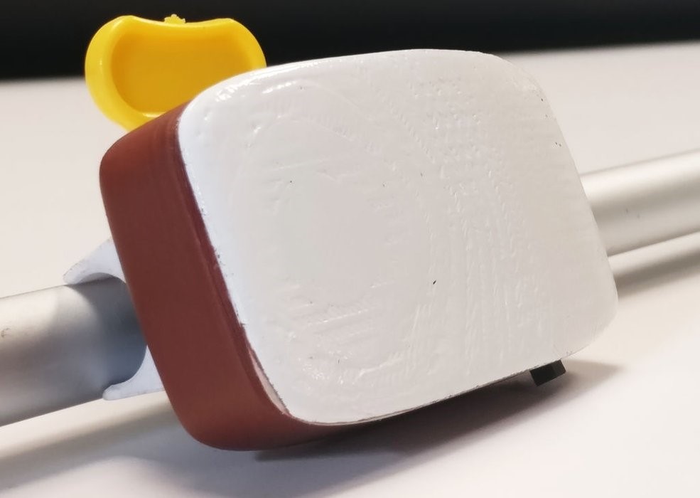
This pod is then clamped onto a white-cane as shown in the video. You can also make-do without the Pod casing, and perhaps tape the system to any stick, or pipe. As long as the MPU6050 axis alignment is consistent, you should be good to go.
Software
Get the latest Arduino IDE. This
instructable has been tested with Arduino version 1.8.5 on Windows 10. A good
tutorial to get the MKR1000 up and running can be found
here. We recommend running the
blink example to verify the setup.
Tools:
- Solder Gun
- Screws
- Star Screw Driver
- Insulation Tape
Step 2: Connections
We provide video instructions for two types of setup: a) raw set-up, and b) a stand-alone full-fledged GesturePod. Instructions for the raw set-up is described in the first video. The full fledged pod builds upon the raw set-up and is described in the second video.
- The raw set-up will enable you to implement the full Machine Learning
Algorithm without any loss in functionality. The connections are described
below:
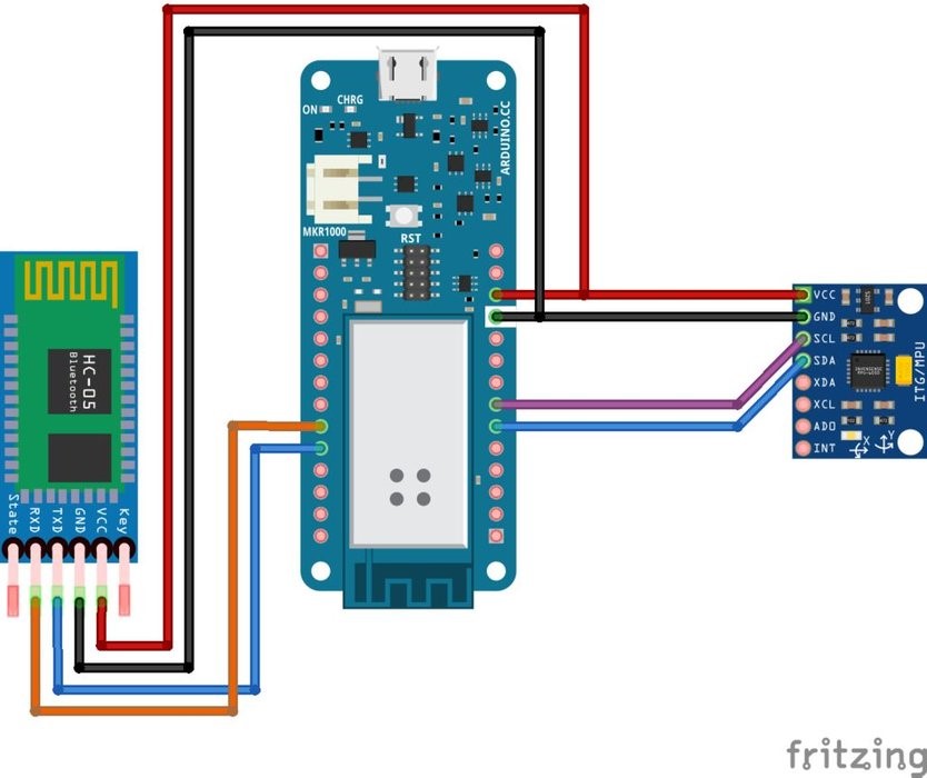
MKR1000 ----------------> HM10 VCC ----------------> VCC GND ----------------> GND 0 (DO) ----------------> RX 1 (D1) ----------------> TX MKR1000 ----------------> MPU6050 VCC ----------------> VCC GND ----------------> GND SDA (D11) ----------------> SDA SCL (D12) ----------------> SCL - The full fledged pod integrates the raw-set up along with a battery and switch - thereby, helping use the system without any connections to a power source, while conserving the battery when the system is turned off.
We recommend running the testMPU.ino example to verify MPU6050 connection.
Step 3: Components housing
After ensuring data can be polled from the MPU, you can now encapsulate the electronics into the casing that can be 3D printed using files provided here. Ensure you have the following 3 parts:
- Pod Base
- Pod Cap
- Clamp Support
First, the MPU is housed in the cavity in the pod base. The MKR1000 is then placed on top of the MPU6050 on the columnar supports. Finally, the HM-10 BLE module is suspended between the projections in the pod cap. The cap and the base are then joined together and fastened with wedge joints. Further, there is support provided for screws to further bolster mechanical support. After attaching the clamp to the pod, you can now clamp the system to the Interactive cane as shown.
Note: Take care to align the MPU to the axis of the pod, as shown in the video.
Step 4: Burn the code onto MKR1000 and connect to phone
You are now just a step away from implementing gesture recognition on edge device..!
Download the code / clone the repository from onMKR1000.ino. Build and upload the code using Arduino IDE. Remember to select MKR1000 as the Board. Open your Serial monitor and set the BAUD rate to 115200. You can now notice the predicted classes. Perform the gestures as demonstrated in the Integrating with cane video and the corresponding gestures will be predicted.
The gesture detected are also transmitted over BLE. You can use nrF Connect app to connect over BLE, and receive the gestures on your phone. To use the gestures detected to trigger corresponding actions on the phone, you can download and install the “Interactive Cane” app from [Coming Soon..!]. Remember to give all necessary permissions and turn the Bluetooth and location services on.
Note: If you are using BLE then it is necessary to have a phone that supports BLE.
What Next?
This tutorial focused on building the GesturePod, and deploying a pre-trianed machine learning model to recognize gestures. The next tutorial will teach you - how to train, and deploy a machine learning model to recognize your own gestures. Know enough to get started already? Head over to here to start training a new model to recognize your custom gestures.
The Things Network Conference - A shorter tutorial
Paul Foster created a shorter (and better !?) tutorial for the hands on workshop at The Things Network Conference, UK (2019). An Adafruit Trinket M0 is used instead of the MKR1000. Further, this basic GesturePod indicates gestures recognised (respecting the British-English spelling, considering the event was held in the UK :D) by using the RGB LED on the Adafruit Trinket M0, rather than via Bluetooth as in the full GesturePod implementation. The tutorial also guides you on how to train a new model for custom gestures.
Did you make this project? Share it with us! We welcome feed-back, comments, and suggestions - please let us know what you think at edgeml@microsoft.com.