G3000 Electronic Stability and Protection (ESP)
Introduction
The G3000 optionally supports simulation of Garmin's Electronic Stability and Protection (ESP) feature. ESP is a safety feature that automatically applies forces to an airplane's pitch/roll controls to aid in recovery from unusual attitude, overspeed, or underspeed conditions. ESP can only be engaged when the autopilot is off and typically also requires a minimum above-ground height for engagement.
The following sections will walk you through how to enable and configure ESP for the G3000.
Enabling ESP
By default, ESP is disabled. To enable ESP, two things need to be done.
First, the <Esp> tag must be added to panel.xml.
Second, an MFD plugin must return an instance of G3000EspDefinition from its getEspDefinition() method.
Accessing ESP Data
When ESP is enabled, the MFD plugin's onEspCreated() method is called. The method is passed references to two objects:
- The created ESP instance, which implements
G3000EspInterface. - The provider from which ESP sources its data, which implements
EspDataProvider.
A plugin can use these references to observe and react to ESP data.
Defining ESP Parameters
ESP parameters are defined by the G3000EspDefinition object returned by the MFD plugin's getEspDefinition() method.
Arming Criteria
ESP must be armed before it can apply control forces during abnormal attitude or speed conditions. Non-configurable criteria for ESP arming include:
- Attitude data must be available.
- The autopilot must be off.
- The airplane cannot be on the ground.
There are also additional configurable arming criteria:
- The airplane's above ground height (AGL).
- The airplane's pitch angle.
- The airplane's roll angle.
Configuring AGL Arming Criteria
To configure the AGL criteria for arming, use the following properties of G3000EspDefinition:
armAglThreshold(required)disarmAglThreshold(required)canArmWhenAglInvalid
The following example configures ESP to arm when AGL is greater than or equal to 220 feet and disarm when AGL is less than 200 feet. It also allows arming when AGL data is not available.
import { registerPlugin } from '@microsoft/msfs-sdk';
import { G3000EspDefinition } from '@microsoft/msfs-wtg3000-common';
import { AbstractG3000MfdPlugin } from '@microsoft/msfs-wtg3000-mfd';

class EspPlugin extends AbstractG3000MfdPlugin {

  public getEspDefinition(): G3000EspDefinition {
    return {
      armAglThreshold: 220,
      disarmAglThreshold: 200,
      canArmWhenAglInvalid: true,
      // ...
    };
  }

}

registerPlugin(EspPlugin);
AGL data is sourced from GPS/FMS position data.
Configuring Pitch/Roll Angle Arming Criteria
To configure the pitch and roll angle criteria for arming, use the following properties of G3000EspDefinition:
armMinPitchLimitarmMaxPitchLimitarmRollLimit
The following example configures ESP to arm only when pitch angle is between -50 and 50 degrees and when roll angle is less than or equal to 75 degrees.
import { registerPlugin } from '@microsoft/msfs-sdk';
import { G3000EspDefinition } from '@microsoft/msfs-wtg3000-common';
import { AbstractG3000MfdPlugin } from '@microsoft/msfs-wtg3000-mfd';

class EspPlugin extends AbstractG3000MfdPlugin {

  public getEspDefinition(): G3000EspDefinition {
    return {
      armMinPitchLimit: -50,
      armMaxPitchLimit: 50,
      armRollLimit: 75,
      // ...
    };
  }

}

registerPlugin(EspPlugin);
Pitch angles for ESP use the sim's sign convention for pitch: positive angles represent downward pitch.
Miscellaneous Arming Critera
In addition to the built-in arming criteria, you can define additional miscellaneous arming criteria by using the isArmingInhibited property of G3000EspDefinition. This optional property accepts a boolean-valued Accessible that controls whether arming is inhibited. Arming will be inhibited as long as the accessible's value is true. When the accessible's value is false, arming is still subject to the built-in arming criteria.
If isArmingInhibited is not defined, then only the built-in arming criteria are used.
Control Force Parameters
ESP applies force to the airplane's pitch and roll controls to aid in recovery when the airplane exceeds certain attitude or speed limits. The way this is implemented in the sim is that when ESP applies a force to a control axis (either pitch or roll), the control axis position that commands a neutral control surface position (aka the neutral command position) is moved away from the neutral control axis position in the direction opposite to the force being applied. The end result is that at the neutral control axis position, control surfaces are deflected as if the control axis were being "pushed" in the direction of the force, and the user must apply opposite input to return the associated control surface to the neutral position.
Due to the above implementation, the force applied by ESP is defined in terms of how far it moves the neutral command position away from the neutral control axis position (or equivalently, how much control surface deflection is commanded by the neutral control axis position while the force is applied). A force of magnitude 1 moves the neutral command position to the maximum control axis extent (or equivalently, the neutral control axis position commands maximum control surface deflection). A force of magnitude 0.5 moves the neutral command position to half the maximum control axis extent, etc.
The following properties of G3000EspDefinition are used to customize the amount of force ESP applies:
pitchAxisMaxForceUppitchAxisMaxForceDownpitchAxisForceRatepitchAxisUnloadRaterollAxisMaxForcerollAxisForceRaterollAxisUnloadRate
The maximum force properties control the maximum amount of force ESP can apply to a control axis (for the pitch axis, the maximum is defined separately for pitch-up and pitch-down forces). The force rate properties control how quickly ESP can change the amount of force it applies to a control axis while it is armed. The unload rate properties control how quickly ESP can remove force when it changes from armed to disarmed. All rate properties are defined in units of force per second.
Engagement Time Tracking
ESP can track the amount of time it has been engaged on a rolling basis. ESP is considered engaged when it is applying force to a control axis. Engagement time is usually used to activate the autopilot's LVL mode once engagement time within the rolling window exceeds a certain threshold.
The window size for engagement time tracking can be configured with the engagementTimeWindow property of G3000EspDefinition. For example, a value of 20 will cause ESP to track the amount of time it has been engaged for the past 20 seconds. Engagement time data can be accessed from the ESP instance.
A value less than or equal to zero disables engagement time tracking (the default).
Defining ESP Modules
The logic that allows ESP to apply force in response to limits being exceeded is provided by modules. ESP does not include any modules by default, so it is up to the plugin to define and add modules to ESP.
Modules are added to ESP by including factories that create and return modules in the moduleFactories property of G3000EspDefinition. Generally, each module is responsible for applying force in response to a single type of limit exceedance. Modules must implement the EspModule interface.
If multiple modules apply force to the same control axis simultaneously, then the forces are summed.
You can create modules from scratch if you wish. However, it is recommended to use one of the pre-defined modules provided in msfs-garminsdk for convenience. The following subsections will describe how to use the pre-defined modules to implement the most commonly encountered real-world ESP behaviors.
Roll Engagement
Roll engagement protects against excessive roll angles. When roll angle (in either direction) exceeds a threshold value, roll engagement will apply a force to the roll axis in the opposite direction. The magnitude of the force is typically proportional to the amount by which roll angle has exceeded the limit. Force is applied until roll angle is reduced below a threshold value that is usually lower than the threshold for engagement.
Roll engagement is implemented by EspRollModule. The following example shows how to add a typical roll engagement setup to ESP using EspRollModule.
import { MathUtils, registerPlugin } from '@microsoft/msfs-sdk';
import { EspData, EspRollModule } from '@microsoft/msfs-garminsdk';
import { G3000EspDefinition } from '@microsoft/msfs-wtg3000-common';
import { AbstractG3000MfdPlugin } from '@microsoft/msfs-wtg3000-mfd';

class EspPlugin extends AbstractG3000MfdPlugin {

  public getEspDefinition(): G3000EspDefinition {
    return {
      // ...
      moduleFactories: [
        () => new EspRollModule(
          'roll', // ID is used to identify the module. Must be unique.
          {
            engageRoll: 45, // Roll angle threshold for engagement
            disengageRoll: 30, // Roll angle threshold for disengagement
            getForceToApply: (data: Readonly<EspData>): number => {
              // Applies a force in the direction opposite to the airplane's current roll angle.
              // The magnitude of the force increases from a minimum of 0.1 at 30 degrees of roll
              // to a maximum of 0.3 at 60 degrees roll.
              return -Math.sign(data.roll) * MathUtils.lerp(Math.abs(data.roll), 30, 60, 0.1, 0.3, true, true);
            },
            canEngageWhenAglInvalid: true // Allow this module to engage when AGL data is invalid
          }
        )
      ]
    };
  }

}

registerPlugin(EspPlugin);
Roll Limit Indicators
ESP roll engagement is typically accompanied by roll limit indicators on the PFD attitude indicator:
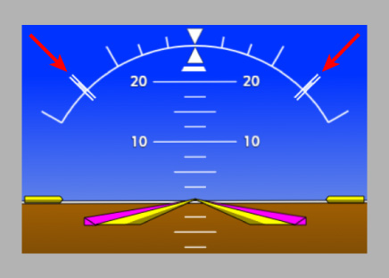
The roll limit indicators are generally used to depict the threshold for roll engagement when roll engagement is not active, and they move to depict the threshold for roll engagement deactivation when roll engagement is active.
To configure roll limit indicators with the above behavior, you can bind the roll limit indicators to specific event bus topics via panel.xml:
<Horizon>
  <RollLimit>
    <LeftRoll>
      <Bus>esp_roll_limit_indicator_left_limit</Bus>
    </LeftRoll>
    <RightRoll>
      <Bus>esp_roll_limit_indicator_right_limit</Bus>
    </RightRoll>
  </RollLimit>
</Horizon>
Then use a plugin to publish the appropriate values to the event bus topics based on the state of ESP:
import { ClockEvents, registerPlugin, Subject } from '@microsoft/msfs-sdk';
import { EspData, EspDataProvider, EspOperatingMode, EspRollModule } from '@microsoft/msfs-garminsdk';
import { G3000EspInterface } from '@microsoft/msfs-wtg3000-common';
import { AbstractG3000MfdPlugin } from '@microsoft/msfs-wtg3000-mfd';

class EspPlugin extends AbstractG3000MfdPlugin {

  public onEspCreated(esp: G3000EspInterface, dataProvider: EspDataProvider): void {
    const rollModule = esp.getModule('roll') as EspRollModule;

    const leftRollLimit = Subject.create<number>(NaN, SubscribableUtils.NUMERIC_NAN_EQUALITY);
    const rightRollLimit = Subject.create<number>(NaN, SubscribableUtils.NUMERIC_NAN_EQUALITY);

    leftRollLimit.sub(limit => { this.binder.bus.pub('esp_roll_limit_indicator_left_limit', limit, true, true); }, true);
    rightRollLimit.sub(limit => { this.binder.bus.pub('esp_roll_limit_indicator_right_limit', limit, true, true); }, true);

    this.binder.bus.getSubscriber<ClockEvents>().sub('realTime')
      .handle(() => {
        if (esp.operatingMode.get() === EspOperatingMode.Armed) {
          const engageData = rollModule.getEngageData();
          leftRollLimit.set(engageData.engageMode === 'left' ? engageData.disengageRoll : engageData.engageRoll);
          rightRollLimit.set(engageData.engageMode === 'right' ? engageData.disengageRoll : engageData.engageRoll);
        } else {
          // Hide the roll limit indicators when ESP is not armed.
          leftRollLimit.set(NaN);
          rightRollLimit.set(NaN);
        }
      });
  }

}

registerPlugin(EspPlugin);
Pitch Engagement
Pitch engagement protects against excessive pitch angles. When pitch angle in a certain direction exceeds a threshold value, pitch engagement will apply a force to the pitch axis in the opposite direction. The magnitude of the force is typically dependent on the pitch angle and the direction of pitch travel. Force is applied until pitch angle is reduced below a threshold value that is usually lower than the threshold for engagement.
Pitch engagement can be applied to excessive pitch up angles, excessive pitch down angles, both, or neither.
Pitch engagement is implemented by EspPitchModule. Each instance of EspPitchModule implements pitch engagement for one direction (up or down) of excessive pitch angle. The following example shows how to add a typical pitch engagement setup (both directions) to ESP using EspPitchModule.
import { MathUtils, registerPlugin } from '@microsoft/msfs-sdk';
import { EspData, EspPitchModule } from '@microsoft/msfs-garminsdk';
import { G3000EspDefinition } from '@microsoft/msfs-wtg3000-common';
import { AbstractG3000MfdPlugin } from '@microsoft/msfs-wtg3000-mfd';

class EspPlugin extends AbstractG3000MfdPlugin {

  public getEspDefinition(): G3000EspDefinition {
    return {
      // ...
      moduleFactories: [
        () => new EspPitchModule(
          'pitch-up', // ID is used to identify the module. Must be unique.
          {
            exceedDirection: 'up', // Module is configured for excessive pitch up engagement
            engagePitch: -20, // Pitch angle threshold for engagement
            disengagePitch: -15, // Pitch angle threshold for disengagement
            getForceToApply: (data: Readonly<EspData>): number => {
              // Applies a force in the direction opposite to the airplane's current pitch angle.
              // The magnitude of the force increases as the magnitude of the pitch angle increases
              // and decreases as the rate of change of pitch angle increases toward neutral pitch.
              const pitchForce = MathUtils.lerp(data.pitch, -15, -25, 0.1, 0.3, true, true);
              const pitchRateForce = data.pitchRate * -0.02;
              return MathUtils.clamp(pitchForce + pitchRateForce, 0.1, 0.3);
            },
            canEngageWhenAglInvalid: false // Do not allow this module to engage when AGL data is invalid
          }
        ),
        () => new EspPitchModule(
          'pitch-down', // ID is used to identify the module. Must be unique.
          {
            exceedDirection: 'down', // Module is configured for excessive pitch down engagement
            engagePitch: 22, // Pitch angle threshold for engagement
            disengagePitch: 12, // Pitch angle threshold for disengagement
            getForceToApply: (data: Readonly<EspData>): number => {
              // Applies a force in the direction opposite to the airplane's current pitch angle.
              // The magnitude of the force increases as the magnitude of the pitch angle increases
              // and decreases as the rate of change of pitch angle increases toward neutral pitch.
              const pitchForce = MathUtils.lerp(data.pitch, 12, 27, -0.1, -0.3, true, true);
              const pitchRateForce = data.pitchRate * -0.02;
              return MathUtils.clamp(pitchForce + pitchRateForce, -0.1, -0.3);
            },
            canEngageWhenAglInvalid: true // Allow this module to engage when AGL data is invalid
          }
        )
      ]
    };
  }

}

registerPlugin(EspPlugin);
Pitch angles for ESP use the sim's sign convention for pitch: positive angles represent downward pitch.
Airspeed Protection
Airspeed protection combats excessively high or low airspeed. When airspeed in a certain direction exceeds a threshold value, airspeed protection will apply a force to the pitch axis to raise or lower the nose in an attempt to decrease or increase airspeed. The magnitude of the force is typically proportional to the amount by which airspeed has exceeded the limit. Force is applied until airspeed is brought back within a threshold value that is usually more stringent than the threshold for engagement.
Airspeed protection can be applied to high airspeeds, low airspeeds, both, or neither.
Airspeed protection is implemented by EspAirspeedModule. Each instance of EspAirspeedModule implements airspeed protection for one direction (high or low) of excessive airspeed. The following example shows how to add a typical airspeed protection setup (both directions) to ESP using EspAirspeedModule.
import { MathUtils, registerPlugin } from '@microsoft/msfs-sdk';
import { EspAirspeedModule, EspData } from '@microsoft/msfs-garminsdk';
import { G3000EspDefinition } from '@microsoft/msfs-wtg3000-common';
import { AbstractG3000MfdPlugin } from '@microsoft/msfs-wtg3000-mfd';

class EspPlugin extends AbstractG3000MfdPlugin {

  public getEspDefinition(): G3000EspDefinition {
    return {
      // ...
      moduleFactories: [
        () => new EspAirspeedModule(
          'airspeed-high', // ID is used to identify the module. Must be unique.
          {
            exceedDirection: 'high', // Module is configured for engagement for excessively high airspeeds
            engageIas: 250, // indicated airspeed threshold for engagement
            disengageIas: 240, // indicated airspeed threshold for disengagement
            getForceToApply: (data: Readonly<EspData>): number => {
              // Applies a force to raise the nose. The magnitude of the force increases from
              // a minimum of 0.1 at 240 knots to a maximum of 0.3 at 270 knots.
              return MathUtils.lerp(data.ias, 240, 270, -0.1, -0.3, true, true);
            },
            canEngageWhenAglInvalid: true // Allow this module to engage when AGL data is invalid
          }
        ),
        () => new EspAirspeedModule(
          'airspeed-low', // ID is used to identify the module. Must be unique.
          {
            exceedDirection: 'low', // Module is configured for engagement for excessively low airspeeds
            engageIas: 75, // indicated airspeed threshold for engagement
            disengageIas: 85, // indicated airspeed threshold for disengagement
            getForceToApply: (data: Readonly<EspData>): number => {
              // Applies a force to lower the nose. The magnitude of the force increases from
              // a minimum of 0.1 at 85 knots to a maximum of 0.3 at 65 knots.
              return MathUtils.lerp(data.ias, 85, 65, 0.1, 0.3, true, true);
            },
            canEngageWhenAglInvalid: false // Do not allow this module to engage when AGL data is invalid
          }
        )
      ]
    };
  }

}

registerPlugin(EspPlugin);
Pitch angles for ESP use the sim's sign convention for pitch: positive angles represent downward pitch.
Angle of Attack Protection
Angle of attack protection combats excessively high angle of attack (AOA). When AOA exceeds a threshold value, AOA protection will apply a force to the pitch axis to lower the nose. The magnitude of the force is typically proportional to the amount by which AOA has exceeded the limit. Force is applied until AOA is brought back within a threshold value that is usually lower than the threshold for engagement.
AOA protection is implemented by EspAoaModule. The following example shows how to add a typical AOA protection setup to ESP using EspAoaModule.
import { MathUtils, registerPlugin } from '@microsoft/msfs-sdk';
import { EspAoaModule, EspData } from '@microsoft/msfs-garminsdk';
import { G3000EspDefinition } from '@microsoft/msfs-wtg3000-common';
import { AbstractG3000MfdPlugin } from '@microsoft/msfs-wtg3000-mfd';

class EspPlugin extends AbstractG3000MfdPlugin {

  public getEspDefinition(): G3000EspDefinition {
    return {
      // ...
      moduleFactories: [
        () => new EspAoaModule(
          'aoa', // ID is used to identify the module. Must be unique.
          {
            engageAoa: 22, // AOA threshold (degrees) for engagement
            disengageAoa: 20, // AOA threshold (degrees) for disengagement
            getForceToApply: (data: Readonly<EspData>): number => {
              // Applies a force to lower the nose. The magnitude of the force increases from
              // a minimum of 0.1 at 20 degrees AOA to a maximum of 0.3 at 25 degrees AOA.
              return MathUtils.lerp(data.aoa, 20, 25, 0.1, 0.3, true, true);
            },
            canEngageWhenAglInvalid: false // Do not allow this module to engage when AGL data is invalid
          }
        )
      ]
    };
  }

}

registerPlugin(EspPlugin);
Pitch angles for ESP use the sim's sign convention for pitch: positive angles represent downward pitch.
Handling Applied ESP Force
When ESP applies a force to a control axis, this force must be handled in some way to make the control axis behave appropriately as if the force were applied. Without any handling, ESP force won't have any effect on the pitch and roll control axes.
By default, when ESP is enabled, it creates a manager that adjusts how pitch and roll control axis inputs are interpreted to obtain the desired behavior for applied ESP forces. This manager requires no additional setup. However, because the manager runs in the JS environment and uses key event intercepts to reinterpret control axis inputs, it incurs a small but non-negligible input delay (roughly 2 frames, which translates to ~66 milliseconds at an average framerate of 30).
If this input delay is not acceptable, then you may opt to use an alternate strategy for handling ESP force that relies on XML model behaviors.
The following subsections describe how to use the default and model behaviors strategies.
Default ESP Force Handling
To use the default handling strategy, ensure that the omitControlInputManager property of G3000EspDefinition is set to false. If the property is left undefined, it will default to false.
Next, control axis input handling can be configured using the controlInputManagerOptions property of G3000EspDefinition. This property accepts an instance of EspControlInputManagerOptions. Most options should be left to their default values, since the defaults were chosen to replicate the sim's native handling of control axis inputs. However, it is recommended (but not required) to manually configure the options in the following example code:
import { registerPlugin } from '@microsoft/msfs-sdk';
import { G3000EspDefinition } from '@microsoft/msfs-wtg3000-common';
import { AbstractG3000MfdPlugin } from '@microsoft/msfs-wtg3000-mfd';

class EspPlugin extends AbstractG3000MfdPlugin {

  public getEspDefinition(): G3000EspDefinition {
    return {
      // ...
      omitControlInputManager: false,
      controlInputManagerOptions: {

        pitchAxisIncrOptions: {
          oneHalfTas: 100,
          oneEighthTas: 180
        },

        rollAxisIncrOptions: {
          oneHalfTas: 200,
          oneEighthTas: 1000
        }

      }
    };
  }

}

registerPlugin(EspPlugin);
When processing inputs that increment or decrement the control axis position, the above options define the the true airspeeds, in knots, at which the input increment is reduced to one-half and one-eighth the base amount. For best results, these parameters should be set to match what is defined in the gameplay.cfg file's elevator (pitch) and aileron (roll) parameters, under the [KEYBOARD_RESPONSE] section.
Model Behaviors ESP Force Handling
To use the model behaviors handling strategy, first disable the default handling by setting the omitControlInputManager property of G3000EspDefinition to true:
import { registerPlugin } from '@microsoft/msfs-sdk';
import { G3000EspDefinition } from '@microsoft/msfs-wtg3000-common';
import { AbstractG3000MfdPlugin } from '@microsoft/msfs-wtg3000-mfd';

class EspPlugin extends AbstractG3000MfdPlugin {

  public getEspDefinition(): G3000EspDefinition {
    return {
      // ...
      omitControlInputManager: true
    };
  }

}

registerPlugin(EspPlugin);
Next, publish the applied ESP forces to two LVars. The LVars can be named as you wish, but the recommended names are given in the example code below:
import { registerPlugin, SimVarValueType } from '@microsoft/msfs-sdk';
import { EspData, EspDataProvider } from '@microsoft/msfs-garminsdk';
import { G3000EspInterface } from '@microsoft/msfs-wtg3000-common';
import { AbstractG3000MfdPlugin } from '@microsoft/msfs-wtg3000-mfd';

class EspPlugin extends AbstractG3000MfdPlugin {

  public onEspCreated(esp: G3000EspInterface, dataProvider: EspDataProvider): void {
    esp.pitchAxisForce.sub(force => {
      SimVar.SetSimVarValue('L:Esp_Pitch_Control_Axis_Force', SimVarValueType.Number, force);
    }, true);

    esp.rollAxisForce.sub(force => {
      SimVar.SetSimVarValue('L:Esp_Roll_Control_Axis_Force', SimVarValueType.Number, force);
    }, true);
  }

}

registerPlugin(EspPlugin);
Finally, use the WT_G3000_ESP_Pitch_Control_Axis_Template and WT_G3000_ESP_Roll_Control_Axis_Template model behaviors templates in your airplane. These templates can be imported from the G3000 ESP.xml model behaviors file:
<Include ModelBehaviorFile="WT\G3000\ESP.xml"/>
When using the templates, you must provide the names of the LVars (without the L: prefix) to which the ESP force values have been published (this can be omitted if you used the recommended LVar names in the above example). Additionally, it is recommended to provide the following parameters:
| Parameter | Description |
|---|---|
INCR_RESP_HALF_TAS | When processing inputs that increment or decrement the control axis position: the true airspeed, in knots, at which the input increment is reduced to one-half the base amount. A value less than or equal to zero disables all adjustments to the increment based on airspeed. Defaults to 0. |
INCR_RESP_EIGHTH_TAS | When processing inputs that increment or decrement the control axis position: the true airspeed, in knots, at which the input increment is reduced to one-eighth the base amount. Defaults to 0. |
For best results, these parameters should be set to match what is defined in the gameplay.cfg file's elevator (pitch) and aileron (roll) parameters, under the [KEYBOARD_RESPONSE] section.
<UseTemplate Name="WT_G3000_ESP_Pitch_Control_Axis_Template">
  <FORCE_VAR>Esp_Pitch_Control_Axis_Force</FORCE_VAR>
  <INCR_RESP_HALF_TAS>100</INCR_RESP_HALF_TAS>
  <INCR_RESP_EIGHTH_TAS>180</INCR_RESP_EIGHTH_TAS>
</UseTemplate>
<UseTemplate Name="WT_G3000_ESP_Roll_Control_Axis_Template">
  <FORCE_VAR>Esp_Roll_Control_Axis_Force</FORCE_VAR>
  <INCR_RESP_HALF_TAS>200</INCR_RESP_HALF_TAS>
  <INCR_RESP_EIGHTH_TAS>1000</INCR_RESP_EIGHTH_TAS>
</UseTemplate>
The templates accept additional parameters that can be used to adjust how control axis input events are processed. It is recommended to omit these parameters in order to use their default values, since the defaults were chosen to replicate the sim's native handling of control axis inputs.