G3000 panel.xml Tag Documentation
<AvionicsType>
Defines whether the installation is of type G3000 or G5000.
Properties
| Scope | Inherits | Singleton | Optional |
|---|---|---|---|
| Global | No | Yes | Yes |
Attributes
None.
Content
'G3000' or 'G5000'.
Default Value
<AvionicsType>G3000</AvionicsType>
<Sensors>
Defines the various sensors installed on the aircraft and connected to the G3000.
Properties
| Scope | Inherits | Singleton | Optional |
|---|---|---|---|
| Global | No | Yes | Yes |
Attributes
| Name | Value | Optional (Default) | Description |
|---|---|---|---|
| adc‑count | Integer in range [1, ∞) | Yes (1) | The number of installed ADC sensors. |
| ahrs‑count | Integer in range [1, ∞) | Yes (1) | The number of installed AHRS sensors. |
Child Tags
Default Value
<Sensors adc-count="1" ahrs-count="1">
  <Adc index="1" airspeed-indicator="1"></Adc>
  <Ahrs index="1" attitude-indicator="1" direction-indicator="1"></Ahrs>
  <Aoa></Aoa>
  <MarkerBeacon></MarkerBeacon>
</Sensors>
<Adc>
Defines options and electrical power logic for one ADC sensor. One of these tags should be created for each installed ADC sensor.
Properties
| Scope | Inherits | Singleton | Optional |
|---|---|---|---|
<Sensors> | No | No | Yes |
Attributes
| Name | Value | Optional (Default) | Description |
|---|---|---|---|
| index | Integer in range [1, ∞) | No | The (1-based) index of the tag's ADC sensor. |
| airspeed‑indicator | Integer in range [1, ∞) | No | The (1-based) index of the sim airspeed indicator from which to source data. |
Child Tags
<Electric>(optional)- The logic determining whether the sensor is powered. If not provided, the sensor is always considered to be powered.
Default Value
<Adc index="1" airspeed-indicator="1"></Adc>
<Ahrs>
Defines options and electrical power logic for one AHRS sensor. One of these tags should be created for each installed AHRS sensor.
Properties
| Scope | Inherits | Singleton | Optional |
|---|---|---|---|
<Sensors> | No | No | Yes |
Attributes
| Name | Value | Optional (Default) | Description |
|---|---|---|---|
| index | Integer in range [1, ∞) | No | The (1-based) index of the tag's AHRS sensor. |
| attitude‑indicator | Integer in range [1, ∞) | No | The (1-based) index of the sim attitude indicator from which to source data. |
| direction‑indicator | Integer in range [1, ∞) | No | The (1-based) index of the sim direction indicator from which to source data. |
Child Tags
<Electric>(optional)- The logic determining whether the sensor is powered. If not provided, the sensor is always considered to be powered.
Default Value
<Ahrs index="1" attitude-indicator="1" direction-indicator="1"></Ahrs>
<Aoa>
Defines options and electrical power logic for the angle of attack computer.
Properties
| Scope | Inherits | Singleton | Optional |
|---|---|---|---|
<Sensors> | No | Yes | Yes |
Attributes
None.
Child Tags
<Electric>(optional)- The logic determining whether the AoA computer is powered. If not provided, the computer is always considered to be powered.
<StallAoa><ZeroLiftAoa>
Default Value
<Aoa></Aoa>
<StallAoa>
Defines the value of the stall (critical) angle of attack, in degrees, for an angle of attack computer. If this tag is not present, then the angle of attack computer will use the value of the STALL ALPHA SimVar as the stall angle of attack.
Properties
| Scope | Inherits | Singleton | Optional |
|---|---|---|---|
<Aoa> | No | Yes | Yes |
Attributes
None.
Content
A <Number> tag, a <Bus> tag, or a numeric operator on the former.
Default Value
None.
<ZeroLiftAoa>
Defines the value of the zero-lift angle of attack, in degrees, for an angle of attack computer. If this tag is not present, then the angle of attack computer will use the value of the ZERO LIFT ALPHA SimVar as the zero-lift angle of attack.
Properties
| Scope | Inherits | Singleton | Optional |
|---|---|---|---|
<Aoa> | No | Yes | Yes |
Attributes
None.
Content
A <Number> tag, a <Bus> tag, or a numeric operator on the former.
Default Value
None.
<MarkerBeacon>
Defines options and electrical power logic for the marker beacon receiver.
Properties
| Scope | Inherits | Singleton | Optional |
|---|---|---|---|
<Sensors> | No | Yes | Yes |
Attributes
None.
Child Tags
<Electric>(optional)- The logic determining whether the sensor is powered. If not provided, the sensor is always considered to be powered.
Default Value
<MarkerBeacon></MarkerBeacon>
<RadarAltimeter>
Defines options and electrical power logic for the radar altimeter. If not present, the G3000 will not support a radar altimeter.
Properties
| Scope | Inherits | Singleton | Optional |
|---|---|---|---|
<Sensors> | No | Yes | Yes |
Attributes
None.
Child Tags
<Electric>(optional)- The logic determining whether the sensor is powered. If not provided, the sensor is always considered to be powered.
Default Value
None.
<WeatherRadar>
Defines options and electrical power logic for the weather radar. If not present, the G3000 will not support a weather radar.
Properties
| Scope | Inherits | Singleton | Optional |
|---|---|---|---|
<Sensors> | No | Yes | Yes |
Attributes
| Name | Value | Optional (Default) | Description |
|---|---|---|---|
| horiz‑scan‑width | Number in range [60, 120] | Yes (90) | The angular scan width (degrees) of the horizontal scan mode. |
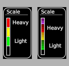
| colors | 'standard' or 'extended' | Yes (standard) | The precipitation color intensity scale to use: 3-color (standard) or 16-color (extended). |
| min‑gain | Number | Yes (-64) | The minimum user-selectable gain value (dBZ). |
| max‑gain | Number | Yes (12) | The maximum user-selectable gain value (dBZ). |
Standard color scale (left) versus extended color scale (right):
Child Tags
<Electric>(optional)- The logic determining whether the weather radar is powered. If not provided, the weather radar is always considered to be powered.
<ScanActiveCircuit>- If defined, then the weather radar will draw power from an additional circuit when actively scanning and will enter a failure state if it is configured for active scanning but the additional circuit is unpowered. If not defined, then the weather radar will not draw any additional power when actively scanning.
Default Value
None.
<ScanActiveCircuit>
Defines options related to simulating additional power draw from the weather radar when the radar is actively scanning.
Properties
| Scope | Inherits | Singleton | Optional |
|---|---|---|---|
<WeatherRadar> | No | Yes | Yes |
Attributes
| Name | Value | Optional (Default) | Description |
|---|---|---|---|
| circuit | Integer in range [1, ∞) | No | The index of the electrical circuit to switch on when the weather radar is actively scanning. |
| procedure | Integer in range [1, ∞) | No | The index of the electrical procedure to use to toggle the active scan electrical circuit. The procedure should be of the SetCir type and configured to turn the circuit off, e.g. None#SetCir:1,0. |
Content
None.
Default Value
None.
<IauDefs>
Defines the installed integrated avionics units (IAUs), also known as GIAs.
Properties
| Scope | Inherits | Singleton | Optional |
|---|---|---|---|
| Global | No | Yes | Yes |
Attributes
| Name | Value | Optional (Default) | Description |
|---|---|---|---|
| count | Integer in range [1, ∞) | Yes (1) | The number of installed IAUs. Most aircraft installations typically have two IAUs. |
Child Tags
Default Value
<IauDefs count="1">
  <Iau index="1" default-adc="1" default-ahrs="1" altimeter-source="1" baro-preselect="false"></Iau>
</IauDefs>
<Iau> (<IauDefs>)
Defines options for one integrated avionics units (IAU), also known as a GIA. One of these tags should be created for each installed IAU. Each IAU contains a GPS receiver and a unit that synthesizes geo-position data from various sources. The IAU also collects ADC and AHRS data to forward to other avionics units such as the GDUs and GTCs. Finally, the IAU uses pressure altitude data from the ADC in conjunction with a baro setting to calculate indicated altitude.
Properties
| Scope | Inherits | Singleton | Optional |
|---|---|---|---|
<IauDefs> | No | No | Yes |
Attributes
| Name | Value | Optional (Default) | Description |
|---|---|---|---|
| index | Integer in range [1, ∞) | Yes (1) | The (1-based) index of the tag's IAU. |
| default‑adc | Integer in range [1, ∞) | Yes (1) | The (1-based) index of the default (preferred) ADC sensor from which to source data. |
| default‑ahrs | Integer in range [1, ∞) | Yes (1) | The (1-based) index of the default (preferred) AHRS sensor from which to source data. |
| altimeter‑source | Integer in range [1, ∞) | Yes (1) | The (1-based) index of the sim altimeter from which to source data. |
| baro‑preselect | Boolean | Yes (false) | Whether to support baro pre-select while the baro setting is STD BARO. |
Child Tags
Default Value
<Iau index="1" default-adc="1" default-ahrs="1" altimeter-source="1" baro-preselect="false"></Iau>
<Gps>
Defines options and electrical power logic for a GPS receiver.
Properties
| Scope | Inherits | Singleton | Optional |
|---|---|---|---|
<Iau> | No | Yes | Yes |
Attributes
None.
Child Tags
<Electric>(optional)- The logic determining whether the receiver is powered. If not provided, the receiver is always considered to be powered.
Default Value
<Gps></Gps>
<FmsPosition>
Defines options and electrical power logic for an FMS geo-positioning unit. The FMS geo-positioning unit synthesizes data from GPS receivers, inertial navigation sensors, DME/DME receivers, and ADC/AHRS to derive a geographic position fix.
Properties
| Scope | Inherits | Singleton | Optional |
|---|---|---|---|
<Iau> | No | Yes | Yes |
Attributes
None.
Child Tags
<Electric>(optional)- The logic determining whether the unit is powered. If not provided, the unit is always considered to be powered.
Default Value
<FmsPosition></FmsPosition>
<Radios>
Defines options for radios.
Properties
| Scope | Inherits | Singleton | Optional |
|---|---|---|---|
| Global | No | Yes | Yes |
Attributes
| Name | Value | Optional (Default) | Description |
|---|---|---|---|
| dme‑count | Integer in range [0, 2] | Yes (0) | The number of installed DME radios. |
| adf‑count | Integer in range [0, 2] | Yes (0) | The number of installed ADF radios. |
Content
None.
Default Value
<Radios dme-count="0" adf-count="0" />
<Fms>
Defines options for the FMS, which manages flight plans, flight path calculations, and navigation.
Properties
| Scope | Inherits | Singleton | Optional |
|---|---|---|---|
| Global | No | Yes | Yes |
Attributes
None.
Child Tags
Default Value
<Fms></Fms>
<FlightPath>
Defines options for flight path calculations. These options affect how FMS calculates the flight path used by LNAV. They do not directly affect how the flight director/autopilot will fly the path while in FMS (LNAV) lateral mode.
Properties
| Scope | Inherits | Singleton | Optional |
|---|---|---|---|
<Fms> | No | Yes | Yes |
Attributes
| Name | Value | Optional (Default) | Description |
|---|---|---|---|
| max‑bank | Number in range (0, 40] | Yes (25) | The maximum bank angle (degrees) used when calculating all flight path turns except turn anticipation. |
| low‑bank | Number in range (0, 40] | Yes (12) | The maximum bank angle (degrees) used when calculating all flight path turns except turn anticipation while Low Bank Mode is active. |
Content
None.
Default Value
<FlightPath max-bank="25" low-bank="12" />
<Approach>
Defines options related to how FMS handles approach procedures.
Properties
| Scope | Inherits | Singleton | Optional |
|---|---|---|---|
<Fms> | No | Yes | Yes |
Attributes
| Name | Value | Optional (Default) | Description |
|---|---|---|---|
| rnp‑ar | Boolean | Yes (false) | Whether to support RNP AR approaches. If not supported, RNP AR approaches will not be selectable when loading approaches, will not appear in the procedure list in the GTC airport information page, and will not count as a valid RNAV approach for determining the best approach type displayed in the nearest airports list. |
Child Tags
Default Value
<Approach rnp-ar="false"></Approach>
<Visual>
Defines how FMS builds visual approach procedures.
Properties
| Scope | Inherits | Singleton | Optional |
|---|---|---|---|
<Approach> | No | Yes | Yes |
Attributes
| Name | Value | Optional (Default) | Description |
|---|---|---|---|
| final‑dist | Number in range (0, ∞) | Yes (2.5) | The distance (nautical miles) from the runway fix to the FINAL fix. |
| strght‑dist | Number in range (0, ∞) | Yes (2.5) | The distance (nautical miles) from the FINAL fix to the STRGHT fix. |
Content
None.
Default Value
<Visual final-dist="2.5" strght-dist="2.5" />
<VNAV>
Defines options for VNAV.
Advanced VNAV support enables the GTC PERF page.
Properties
| Scope | Inherits | Singleton | Optional |
|---|---|---|---|
| Global | No | Yes | Yes |
Attributes
| Name | Value | Optional (Default) | Description |
|---|---|---|---|
| advanced | Boolean | Yes (false) | Whether VNAV supports the advanced featureset (climb VNAV, path smoothing, per-constraint user-defined FPAs, and FMS speed). |
Child Tags
Default Value
<VNAV advanced="false"></VNAV>
<FmsSpeeds>
Defines options related to how FMS calculates target airspeeds.
This tag is ignored if advanced VNAV is not supported.
Properties
| Scope | Inherits | Singleton | Optional |
|---|---|---|---|
<VNAV> | No | Yes | Yes |
Attributes
None.
Child Tags
Default Value
<FmsSpeeds></FmsSpeeds>
<GeneralLimits>
Defines the general limits that FMS must always respect when calculating target airspeeds.
Properties
| Scope | Inherits | Singleton | Optional |
|---|---|---|---|
<FmsSpeeds> | No | Yes | Yes |
Attributes
None.
Child Tags
Default Value
<GeneralLimits></GeneralLimits>
<Ias> (<GeneralLimits>)
Defines the general IAS limits that FMS must always respect when calculating target airspeeds.
Properties
| Scope | Inherits | Singleton | Optional |
|---|---|---|---|
<GeneralLimits> | No | Yes | Yes |
Attributes
None.
Child Tags
<Minimum>(optional)- Declares the minimum IAS limit (knots, in range [1, 999]) as its content. If not defined, the minimum defaults to Vs0 from the
[REFERENCE SPEEDS]section offlight_model.cfg.
- Declares the minimum IAS limit (knots, in range [1, 999]) as its content. If not defined, the minimum defaults to Vs0 from the
<Maximum>(optional)- Declares the maximum IAS limit (knots, in range [1, 999]) as its content. If not defined, the maximum defaults to Vne from the
[REFERENCE SPEEDS]section offlight_model.cfg.
- Declares the maximum IAS limit (knots, in range [1, 999]) as its content. If not defined, the maximum defaults to Vne from the
Default Value
<Ias></Ias>
<Mach> (<GeneralLimits>)
Defines the general mach limits that FMS must always respect when calculating target airspeeds.
Properties
| Scope | Inherits | Singleton | Optional |
|---|---|---|---|
<GeneralLimits> | No | Yes | Yes |
Attributes
None.
Child Tags
<Minimum>(optional)- Declares the minimum mach limit (in range [0.01, 0.99]) as its content. If not defined, defaults to 0.2.
<Maximum>(optional)- Declares the maximum mach limit (in range [0.01, 0.99]) as its content. If not defined, defaults to 0.8.
Default Value
<Mach></Mach>
<AirframeLimits>
Defines the maximum airframe limits that FMS must always respect when calculating target airspeeds.
If either the IAS or mach limit is not explicitly defined, then it will default to the respective maximum general speed limit.
Properties
| Scope | Inherits | Singleton | Optional |
|---|---|---|---|
<FmsSpeeds> | No | Yes | Yes |
Attributes
None.
Child Tags
Default Value
<AirframeLimits></AirframeLimits>
<Ias> (<AirframeLimits>)
Defines the maximum IAS limit imposed by the airframe that FMS must respect when calculating target airspeeds.
Properties
| Scope | Inherits | Singleton | Optional |
|---|---|---|---|
<AirframeLimits> | No | Yes | Yes |
Attributes
None.
Content
One of the following:
- Number
- Defines the limit as a constant (knots).
<LookupTable>- Defines the limit as a one-dimensional lookup table that looks up IAS (knots) from pressure altitude (feet).
Default Value
None.
<Mach> (<AirframeLimits>)
Defines the maximum mach limit imposed by the airframe that FMS must respect when calculating target airspeeds.
Properties
| Scope | Inherits | Singleton | Optional |
|---|---|---|---|
<AirframeLimits> | No | Yes | Yes |
Attributes
None.
Content
One of the following:
- Number
- Defines the limit as a constant.
<LookupTable>- Defines the limit as a one-dimensional lookup table that looks up mach from pressure altitude (feet).
Default Value
None.
<ConfigurationSpeeds>
Defines aircraft configuration speed limits (also known as FMS Flap Speeds). These speeds are configurable by the user through the GTC FMS Flap Speeds page.
Up to one gear limit and an arbitrary number of flaps limits may be declared. Limits should be declared in order of decreasing speed. Declaration order will determine the order in which the limits appear in the GTC FMS Flap Speeds page. Additionally, a constraint is enforced on the values of the limits based on their order such that any limit's value must be less than or equal to the values of all limits declared before it. If the user changes the value of a limit through the GTC FMS Flap Speeds page such that the above constraint is violated, the system will automatically change the values of the other limits to satisfy the constraint again.
Properties
| Scope | Inherits | Singleton | Optional |
|---|---|---|---|
<FmsSpeeds> | No | Yes | Yes |
Attributes
None.
Child Tags
Default Value
<ConfigurationSpeeds></ConfigurationSpeeds>
<Flaps> (<ConfigurationSpeeds>)
Declares a single FMS flaps speed limit.
Properties
| Scope | Inherits | Singleton | Optional |
|---|---|---|---|
<ConfigurationSpeeds> | No | No | Yes |
Attributes
| Name | Value | Optional (Default) | Description |
|---|---|---|---|
| name | String | No | The name of the flaps speed limit displayed to the user. |
| extension | Number in range [0, ∞) | No | The minimum flaps extension angle (degrees) required for the limit to take effect. |
| min | Number in range [a, b], where a and b are the minimum and maximum general FMS IAS limits | No | The minimum user-selectable value (knots). |
| max | Number in range (min, b], where b is the maximum general FMS IAS limit | No | The maximum user-selectable value (knots). |
| default | Number in range [min, max] | No | The default value (knots). |
Content
None.
Default Value
None.
<Gear> (<ConfigurationSpeeds>)
Declares the FMS gear speed limit.
Properties
| Scope | Inherits | Singleton | Optional |
|---|---|---|---|
<ConfigurationSpeeds> | No | Yes | Yes |
Attributes
| Name | Value | Optional (Default) | Description |
|---|---|---|---|
| name | String | No | The name of the gear speed limit displayed to the user. |
| extension | Number in range [0, ∞) | No | The minimum gear extension (percent) required for the limit to take effect. |
| min | Number in range [a, b], where a and b are the minimum and maximum general FMS IAS limits | No | The minimum user-selectable value (knots). |
| max | Number in range (min, b], where b is the maximum general FMS IAS limit | No | The maximum user-selectable value (knots). |
| default | Number in range [min, max] | No | The default value (knots). |
Content
None.
Default Value
None.
<Schedules> (<FmsSpeeds>)
Declares pre-defined FMS speed schedules for the climb, cruise, and descent phases. The user can make selections among these schedules in the GTC PERF/VNAV page.
Regardless of how many pre-defined schedules are declared, the user will always be able to select a Pilot-Defined schedule for each of the climb, cruise, and descent phases. These Pilot-Defined schedules allow the user to enter their own custom speed limits.
Properties
| Scope | Inherits | Singleton | Optional |
|---|---|---|---|
<FmsSpeeds> | No | Yes | Yes |
Attributes
None.
Child Tags
Default Value
<Schedules></Schedules>
<ClimbSchedule>
Declares a single FMS climb schedule.
Properties
| Scope | Inherits | Singleton | Optional |
|---|---|---|---|
<Schedules> | No | No | Yes |
Attributes
| Name | Value | Optional (Default) | Description |
|---|---|---|---|
| name | String | No | The name of the schedule displayed to the user. If equal to the empty string, then the schedule will not have an explicit name and will instead only be identified by the values of its speed limits. |
| default | Boolean | Yes (false) | Whether the schedule is the default climb schedule. If multiple climb schedules are declared as the default, only the first (in tree order) will be treated as the default. |
Child Tags
<CruiseSchedule>
Declares a single FMS cruise schedule.
Unlike with climb and descent schedules, you may choose to omit both IAS and mach speed limits for cruise schedules. If these limits are omitted, then the schedule is treated as a non-speed targeting schedule. While the schedule is active, there will be no scheduled speed limits (though other limits, such as flight plan speeds, configuration speeds, etc, will still be in effect). Additionally, FMS will not provide a target speed but instead only provide a maximum allowable speed (determined by the non-schedule speed limits still in effect). These non-speed targeting cruise schedules are meant to be used in conjunction with autothrottle modes that target an engine power setting (e.g. maximum cruise, long-range cruise, etc) instead of a specific airspeed.
Properties
| Scope | Inherits | Singleton | Optional |
|---|---|---|---|
<Schedules> | No | No | Yes |
Attributes
| Name | Value | Optional (Default) | Description |
|---|---|---|---|
| name | String | No | The name of the schedule displayed to the user. If equal to the empty string, then the schedule will not have an explicit name and will instead only be identified by the values of its speed limits. |
| default | Boolean | Yes (false) | Whether the schedule is the default cruise schedule. If multiple cruise schedules are declared as the default, only the first (in tree order) will be treated as the default. |
Child Tags
<DescentSchedule>
Declares a single FMS descent schedule.
Properties
| Scope | Inherits | Singleton | Optional |
|---|---|---|---|
<Schedules> | No | No | Yes |
Attributes
| Name | Value | Optional (Default) | Description |
|---|---|---|---|
| name | String | No | The name of the schedule displayed to the user. If equal to the empty string, then the schedule will not have an explicit name and will instead only be identified by the values of its speed limits. |
| default | Boolean | Yes (false) | Whether the schedule is the default descent schedule. If multiple descent schedules are declared as the default, only the first (in tree order) will be treated as the default. |
Child Tags
Default Value
None.
<Ias> (<Schedules>)
Defines the IAS limit (knots) for an FMS climb, cruise, or descent schedule.
Properties
| Scope | Inherits | Singleton | Optional |
|---|---|---|---|
<ClimbSchedule>, <CruiseSchedule>, or <DescentSchedule> | No | Yes | No |
Attributes
None.
Content
Number in range [a, b], where a and b are the minimum and maximum general FMS IAS limits.
<Mach> (<Schedules>)
Defines the mach limit for an FMS climb, cruise, or descent schedule.
Properties
| Scope | Inherits | Singleton | Optional |
|---|---|---|---|
<ClimbSchedule>, <CruiseSchedule>, or <DescentSchedule> | No | Yes | No |
Attributes
None.
Content
Number in range [a, b], where a and b are the minimum and maximum general FMS mach limits.
<Fpa> (<DescentSchedule>)
Defines the default FPA (degrees) for an FMS descent schedule.
Currently this tag has no effect; all schedules are locked to a default FPA of -3 degrees. A future update will properly enable this functionality.
Properties
| Scope | Inherits | Singleton | Optional |
|---|---|---|---|
<DescentSchedule> | No | Yes | No |
Attributes
None.
Content
Number in range [-1.5, -6].
<Autopilot>
Defines options for the autopilot.
Properties
| Scope | Inherits | Singleton | Optional |
|---|---|---|---|
| Global | No | Yes | Yes |
Attributes
| Name | Value | Optional (Default) | Description |
|---|---|---|---|
| hdg‑sync‑mode | Boolean | Yes (false) | Whether HDG sync mode is supported. If supported, triggering the H:Garmin_AP_HDG_Sync event while a Navigation mode (FMS/GPS, VOR, LOC, BC) is active will toggle HDG sync mode, which continuously syncs the autopilot selected heading with the airplane's heading. |
Child Tags
Default Value
<Autopilot hdg-sync-mode="false"></Autopilot>
<ROL>
Defines options for the autopilot ROL lateral mode director.
Properties
| Scope | Inherits | Singleton | Optional |
|---|---|---|---|
<Autopilot> | No | Yes | Yes |
Attributes
| Name | Value | Optional (Default) | Description |
|---|---|---|---|
| min‑bank | Number in range [0, ∞) | Yes (6) | The minimum bank angle (degrees) supported by the director. If aircraft bank is less than this value when ROL is activated, the director will command wings level instead. |
| max‑bank | Number in range (0, ∞) | Yes (25) | The maximum bank angle (degrees) commanded by the director. If aircraft bank is greater than this value when ROL is activated, the director will command bank equal to this value instead. |
Content
None.
Default Value
<ROL min-bank="6" max-bank="25" />
<HDG>
Defines options for the autopilot HDG lateral mode director.
Properties
| Scope | Inherits | Singleton | Optional |
|---|---|---|---|
<Autopilot> | No | Yes | Yes |
Attributes
| Name | Value | Optional (Default) | Description |
|---|---|---|---|
| max‑bank | Number in range (0, ∞) | Yes (25) | The maximum bank angle (degrees) commanded by the director. |
Content
None.
Default Value
<HDG max-bank="25" />
<VOR>
Defines options for the autopilot VOR lateral mode director.
Properties
| Scope | Inherits | Singleton | Optional |
|---|---|---|---|
<Autopilot> | No | Yes | Yes |
Attributes
| Name | Value | Optional (Default) | Description |
|---|---|---|---|
| max‑bank | Number in range (0, ∞) | Yes (25) | The maximum bank angle (degrees) commanded by the director. |
Content
None.
Default Value
<VOR max-bank="25" />
<LOC>
Defines options for the autopilot LOC lateral mode director.
Properties
| Scope | Inherits | Singleton | Optional |
|---|---|---|---|
<Autopilot> | No | Yes | Yes |
Attributes
| Name | Value | Optional (Default) | Description |
|---|---|---|---|
| max‑bank | Number in range (0, ∞) | Yes (25) | The maximum bank angle (degrees) commanded by the director. |
Content
None.
Default Value
<LOC max-bank="25" />
<FMS>
Defines options for the autopilot FMS/GPS lateral mode director.
Properties
| Scope | Inherits | Singleton | Optional |
|---|---|---|---|
<Autopilot> | No | Yes | Yes |
Attributes
| Name | Value | Optional (Default) | Description |
|---|---|---|---|
| max‑bank | Number in range (0, ∞) | Yes (25) | The maximum bank angle (degrees) commanded by the director. |
Content
None.
Default Value
<FMS max-bank="25" />
<LowBank>
Defines options for the autopilot Low Bank mode.
Properties
| Scope | Inherits | Singleton | Optional |
|---|---|---|---|
<Autopilot> | No | Yes | Yes |
Attributes
| Name | Value | Optional (Default) | Description |
|---|---|---|---|
| max‑bank | Number in range (0, ∞) | Yes (15) | The maximum bank angle (degrees) commanded by the HDG, VOR/LOC, and FMS directors while Low Bank mode is active. |
Content
None.
Default Value
<LowBank max-bank="15" />
<Autothrottle>
Defines whether an autothrottle is installed.
Properties
| Scope | Inherits | Singleton | Optional |
|---|---|---|---|
| Global | No | Yes | Yes |
Attributes
None.
Content
Boolean.
Default Value
<Autothrottle>False</Autothrottle>
<Esp>
Declares support for electronic stability and protection (ESP) feature.
To enable ESP, this tag must be defined and an MFD plugin must return an ESP definition.
Properties
| Scope | Inherits | Singleton | Optional |
|---|---|---|---|
| Global | No | Yes | Yes |
Attributes
None.
Content
None.
Default Value
None.
<VSpeeds>
Defines reference V-speeds for the aircraft.
Properties
| Scope | Inherits | Singleton | Optional |
|---|---|---|---|
| Global | No | Yes | Yes |
Attributes
None.
Child Tags
Default Value
<VSpeeds></VSpeeds>
<Group> (<VSpeeds>)
Defines a reference V-speed group. Each group can contain an arbitrary number of reference V-speeds.
There are four types of V-speed groups:
- General
- Takeoff
- Landing
- Configuration
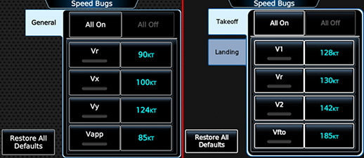
V-speeds in the first three groups are all user-configurable and appear in the GTC Speed Bugs page, with each group having its own tab. If the installation is configured to support takeoff/landing (TOLD) performance calculations, Takeoff and Landing V-speeds (but not General V-speeds) can be calculated and managed by the FMS.
The following image shows examples of the GTC Speed Bugs page when the aircraft is configured to only include the General group (left) and when it is configured to include the Takeoff and Landing groups (right):
Unlike the other types, Configuration V-speeds are not user-configurable and will not appear in the Speed Bugs page. Configuration V-speed bugs are always displayed on the airspeed indicator unless the aircraft is higher than a (optional) pressure altitude threshold.
If more than one <Group> tag of a given type is present, only the first tag in tree order will be used.
Properties
| Scope | Inherits | Singleton | Optional |
|---|---|---|---|
<VSpeeds> | No | No | Yes |
Attributes
| Name | Value | Optional (Default) | Description |
|---|---|---|---|
| type | 'General', 'Takeoff', 'Landing', or 'Configuration' | No | The type of V-speed group. |
| max‑ias | Number in range (0, ∞) | Yes (∞) | The IAS (knots) above which bugs for the group's V-speeds are automatically hidden. Only applies if the group type is 'Takeoff'. |
| hide‑when‑appr‑config | Boolean | Yes (true) | Whether to hide bugs for the group's V-speeds when the airplane is configured for approach. Configured for approach is defined as extending gear or extending flaps from a fully retracted position while the airplane is in the air. Only applies if the group type is 'Takeoff'. |
| max‑altitude | Number in range (0, ∞) | Yes (∞) | The pressure altitude (feet) above which bugs for the group's V-speeds are automatically hidden. Only applies if the group type is 'Configuration'. |
Child Tags
Default Value
None.
<VSpeed>
Defines a reference V-speed.
Properties
| Scope | Inherits | Singleton | Optional |
|---|---|---|---|
<Group> | No | No | Yes |
Attributes
| Name | Value | Optional (Default) | Description |
|---|---|---|---|
| name | String | No | The name of the V-speed. Each V-speed must have a unique name (even across different groups). |
| label | String | Yes ([See Description]) | The label text to display for the V-speed. If not defined, then the label text defaults to 'V[name]', where [name] is the name of the V-speed. |
| editable | Boolean | Yes (true) | Whether the value of the V-speed can be edited by the user. |
Content
One of the following:
- Integer in range (0, ∞)
- Declares the default value of the V-speed as a numeric literal (knots).
- Integer in range (-∞, 0]
- Declares that the V-speed has no default value. The user will have to manually input a value for the V-speed or have FMS compute a value if applicable on every system power-up.
- Sim reference speed key
- Declares the default value of the V-speed as a sim reference speed, as defined in the
[REFERENCE SPEEDS]section offlight_model.cfg. The possible keys are:BestGlideVappVFeVmcVMaxVMinVNeVNoVrVS0VS1VxVyVyse
- Declares the default value of the V-speed as a sim reference speed, as defined in the
Default Value
None.
<Traffic>
Defines the traffic system installed with the aircraft.
There are three types supported traffic systems:
- TIS (Traffic Information Service)
- TAS (Traffic Advisory System)
- TCAS-II
All three traffic system types support optional ADS-B In functionality. When ADS-B In is enabled and active, traffic icons will be rendered with heading/track arrows on traffic displays and ADS-B motion vectors will be supported. Within the sim all traffic is treated as ADS-B traffic (i.e. all traffic is assumed to be broadcasting ADS-B Out).
Properties
| Scope | Inherits | Singleton | Optional |
|---|---|---|---|
| Global | No | Yes | Yes |
Attributes
| Name | Value | Optional (Default) | Description |
|---|---|---|---|
| type | 'TIS', 'TAS', or 'TCAS-II' | Yes (TIS) | The type of traffic system. |
| ads‑b | Boolean | Yes (false) | Whether ADS-B In functionality is supported. |
Child Tags
<Electric>(optional)- The logic determining whether the system is powered. If not provided, the system is always considered to be powered.
Default Value
<Traffic type="TIS" ads-b="false"></Traffic>
<Terrain>
Declares support for and defines options related to a terrain awareness and alerting system.
Two types of terrain systems are supported: TAWS-A and TAWS-B. Different types of terrain systems support different sets of alerts, and the behavior of certain alerts may be different from one system type to another.
Alerting functions are separated into discrete modules. Each terrain system type comes with its own set of default modules. Certain modules may also be configured differently from one terrain system type to another. Additional modules beyond the default set for a system type may be added and default module configurations may be overridden by including module tags within this tag's child <Modules> tag. Default modules may be excluded by including module tags within this tag's child <Exclusions> tag.
The following table lists the default modules for each terrain system type.
| Type | Modules |
|---|---|
| TAWS-A | PDA, EDR, ECR, NCR, Touchdown Callouts (VCO) |
| TAWS-B | PDA, EDR, NCR, Touchdown Callouts (VCO) |
Properties
| Scope | Inherits | Singleton | Optional |
|---|---|---|---|
| Global | No | Yes | Yes |
Attributes
| Name | Value | Optional (Default) | Description |
|---|---|---|---|
| type | 'taws-a' or 'taws-b' | No | The type of terrain system to include. The specified type determines the modules included with the terrain system by default and the default configuration of some modules. |
Child Tags
Default Value
None.
<Modules> (<Terrain>)
Declares modules to include for a configured terrain awareness and alerting system.
If a module declared within this tag does not belong to the terrain system's default set, then the module will be added. If a module declared within this tag does belong to the terrain system's default set, then any configured options for the module will override the default configuration.
Properties
| Scope | Inherits | Singleton | Optional |
|---|---|---|---|
<Terrain> | No | Yes | Yes |
Attributes
None.
Child Tags
Default Value
<Modules></Modules>
<Exclusions> (<Terrain>)
Declares modules to exclude for a configured terrain awareness and alerting system.
If a module declared within this tag belongs to the terrain system's default set or was included via the <Modules> tag, then the module will be excluded from the terrain system.
Properties
| Scope | Inherits | Singleton | Optional |
|---|---|---|---|
<Terrain> | No | Yes | Yes |
Attributes
None.
Child Tags
<Pda><Edr><Ecr><Ncr><TouchdownCallouts>
All of the above child tags have no attributes and no content.
Default Value
<Exclusions></Exclusions>
<Taws>
This tag is deprecated. Please use the <Terrain> tag instead.
Defines options related to TAWS.
Properties
| Scope | Inherits | Singleton | Optional |
|---|---|---|---|
| Global | No | Yes | Yes |
Attributes
None.
Child Tags
Default Value
<Taws></Taws>
<Pda>
Declares support for the terrain system's premature descent alert (PDA) module.
Properties
| Scope | Inherits | Singleton | Optional |
|---|---|---|---|
<Modules> | No | Yes | Yes |
Attributes
None.
Content
None.
Default Value
None.
<Edr>
Declares support for and defines options related to the terrain system's excessive descent rate alert (EDR) module.
Properties
| Scope | Inherits | Singleton | Optional |
|---|---|---|---|
<Modules> | No | Yes | Yes |
Attributes
| Name | Value | Optional (Default) | Description |
|---|---|---|---|
| gpws | Boolean | Yes (true if terrain system type is TAWS-A, and false otherwise) | Whether the alert should function as a GPWS alert. GPWS alerts use radar altimeter data instead of GPS data to derive AGL height. |
Content
None.
Default Value
None.
<Ecr>
Declares support for and defines options related to the terrain system's excessive closure rate alert (ECR) module.
Properties
| Scope | Inherits | Singleton | Optional |
|---|---|---|---|
<Modules> | No | Yes | Yes |
Attributes
| Name | Value | Optional (Default) | Description |
|---|---|---|---|
| flaps‑landing‑min | Number | Yes (-Infinity) | The minimum flaps extension angle, in degrees, that qualifies as a landing flaps configuration. |
| flaps‑landing‑max | Number | Yes (Infinity) | The maximum flaps extension angle, in degrees, that qualifies as a landing flaps configuration. |
| gpws | Boolean | Yes (true if terrain system type is TAWS-A, and false otherwise) | Whether the alert should function as a GPWS alert. GPWS alerts use radar altimeter data instead of GPS data to derive AGL height. |
Content
None.
Default Value
None.
<Ncr>
Declares support for and defines options related to the terrain system's negative climb rate after takeoff alert (NCR) module.
Properties
| Scope | Inherits | Singleton | Optional |
|---|---|---|---|
<Modules> | No | Yes | Yes |
Attributes
| Name | Value | Optional (Default) | Description |
|---|---|---|---|
| gpws | Boolean | Yes (true if terrain system type is TAWS-A, and false otherwise) | Whether the alert should function as a GPWS alert. GPWS alerts use radar altimeter data instead of GPS data to derive AGL height. |
Content
None.
Default Value
None.
<Gsd>
Declares support for and defines options related to the terrain system's glideslope/glidepath deviation (GSD) module.
Properties
| Scope | Inherits | Singleton | Optional |
|---|---|---|---|
<Modules> | No | Yes | Yes |
Attributes
| Name | Value | Optional (Default) | Description |
|---|---|---|---|
| gpws | Boolean | Yes (true if terrain system type is TAWS-A, and false otherwise) | Whether the alert should function as a GPWS alert. GPWS alerts use radar altimeter data instead of GPS data to derive AGL height. |
Content
None.
Default Value
None.
<TouchdownCallouts>
Declares support for and defines options related to the terrain system's touchdown callouts, aka voice callouts (VCO), module.
If an altitude callout tag is not included as a child, then that altitude callout defaults to disabled and not user-configurable.
If at least one altitude callout is user-configurable, then the Touchdown Callouts row in the Alerts tab of the GTC Avionics Settings page will be shown. Otherwise, the row will be hidden.
Properties
| Scope | Inherits | Singleton | Optional |
|---|---|---|---|
<Modules> or <Taws> | No | Yes | Yes |
Attributes
| Name | Value | Optional (Default) | Description |
|---|---|---|---|
| inhibit‑500‑gs‑gp | Boolean | Yes (false) | Whether to inhibit the 500-foot callout when the flight director's GS or GP mode is active. |
Child Tags
Default Value
None.
<Callout> (<TouchdownCallouts>)
Defines options for a single supported terrain system touchdown callout. The tag's content determines which altitude callout the tag applies to.
Properties
| Scope | Inherits | Singleton | Optional |
|---|---|---|---|
<TouchdownCallouts> | No | Yes | Yes |
Attributes
| Name | Value | Optional (Default) | Description |
|---|---|---|---|
| configurable | Boolean | Yes (false) | Whether the user is allowed to enable/disable the callout. |
| enabled | Boolean | Yes (true) | Whether the callout is enabled. If the callout is configurable, this determines the default state of the callout. |
Content
One of the following:
- 500
- 450
- 400
- 350
- 300
- 250
- 200
- 150
- 100
- 50
- 40
- 30
- 20
- 10
Default Value
None.
<PfdAnnunc> (<Terrain>)
Defines options for PFD terrain system annunciations.
Properties
| Scope | Inherits | Singleton | Optional |
|---|---|---|---|
<Terrain> | No | Yes | Yes |
Attributes
| Name | Value | Optional (Default) | Description |
|---|---|---|---|
| omit‑test‑annunc | Boolean | Yes (false) | Whether to omit PFD terrain system test annunciations. Test annunciations alert the user when the system is performing a self test. |
| omit‑status‑annunc | Boolean | Yes (false) | Whether to omit PFD terrain system status annunciations. Status annunciations alert the user of system failures or inavailability. |
| omit‑inhibit‑annunc | Boolean | Yes (false) | Whether to omit PFD terrain system inhibit annunciations. Inhibit annunciations alert the user when one or more system alerts are inhibited. |
Content
None.
Default Value
<PfdAnnunc omit-test-annunc="false" omit-status-annunc="false" omit-inhibit-annunc="false" />
<Map>
Defines options related to map rendering.
Properties
| Scope | Inherits | Singleton | Optional |
|---|---|---|---|
| Global | No | Yes | Yes |
Attributes
| Name | Value | Optional (Default) | Description |
|---|---|---|---|
| airplane‑icon‑src | String | Yes ([path to generic default icon]) | The absolute path of the image file to render as the ownship icon. The front of the airplane must be vertically aligned with the top edge and horizontally aligned with the center of the image. |
| traffic‑range‑label‑radial | Number | Yes (135) | The radial (degrees) on which the Traffic Map range labels are positioned. A value of 0 degrees points horizontally to the right, and increasing angles proceed clockwise. Does not affect the Traffic Inset Map. Typically either 135 or 225 degrees. |
| traffic‑range‑inner‑ring‑show | Boolean | Yes (false) | Whether to display the Traffic Map inner range ring. Note that the inner range label and heading ticks are always shown. |
Content
None.
Default Value
<Map traffic-range-label-radial="135" traffic-range-inner-ring-show="false" />
<Performance>
Defines options related to aircraft performance calculations.
Properties
| Scope | Inherits | Singleton | Optional |
|---|---|---|---|
| Global | No | Yes | No |
Attributes
None.
Child Tags
<Weights>
Defines aircraft weight limits and constants.
Properties
| Scope | Inherits | Singleton | Optional |
|---|---|---|---|
<Performance> | No | Yes | No |
Attributes
None.
Child Tags
<BasicEmpty>
Defines the aircraft's basic empty weight.
Properties
| Scope | Inherits | Singleton | Optional |
|---|---|---|---|
<Weights> | No | Yes | No |
Attributes
| Name | Value | Optional (Default) | Description |
|---|---|---|---|
| unit | 'lb', 'lbs', 'pound', 'pounds', 'kg', 'kgs', 'kilogram', 'kilograms' | Yes (pounds) | The units to use when interpreting the weight value. |
Content
Number in range [0, ∞).
<MaxZeroFuel>
Defines the aircraft's maximum zero-fuel weight.
Properties
| Scope | Inherits | Singleton | Optional |
|---|---|---|---|
<Weights> | No | Yes | No |
Attributes
| Name | Value | Optional (Default) | Description |
|---|---|---|---|
| unit | 'lb', 'lbs', 'pound', 'pounds', 'kg', 'kgs', 'kilogram', 'kilograms' | Yes (pounds) | The units to use when interpreting the weight value. |
Content
Number in range [0, ∞).
<MaxRamp>
Defines the aircraft's maximum ramp weight.
Properties
| Scope | Inherits | Singleton | Optional |
|---|---|---|---|
<Weights> | No | Yes | No |
Attributes
| Name | Value | Optional (Default) | Description |
|---|---|---|---|
| unit | 'lb', 'lbs', 'pound', 'pounds', 'kg', 'kgs', 'kilogram', 'kilograms' | Yes (pounds) | The units to use when interpreting the weight value. |
Content
Number in range [0, ∞).
<MaxTakeoff>
Defines the aircraft's maximum takeoff weight.
Properties
| Scope | Inherits | Singleton | Optional |
|---|---|---|---|
<Weights> | No | Yes | No |
Attributes
| Name | Value | Optional (Default) | Description |
|---|---|---|---|
| unit | 'lb', 'lbs', 'pound', 'pounds', 'kg', 'kgs', 'kilogram', 'kilograms' | Yes (pounds) | The units to use when interpreting the weight value. |
Content
Number in range [0, ∞).
<MaxLanding>
Defines the aircraft's maximum landing weight.
Properties
| Scope | Inherits | Singleton | Optional |
|---|---|---|---|
<Weights> | No | Yes | No |
Attributes
| Name | Value | Optional (Default) | Description |
|---|---|---|---|
| unit | 'lb', 'lbs', 'pound', 'pounds', 'kg', 'kgs', 'kilogram', 'kilograms' | Yes (pounds) | The units to use when interpreting the weight value. |
Content
Number in range [0, ∞).
<MaxPax>
Defines the aircraft's maximum passenger count.
Properties
| Scope | Inherits | Singleton | Optional |
|---|---|---|---|
<Weights> | No | Yes | Yes |
Attributes
None.
Content
Integer in range [0, ∞).
Default Value
<MaxPax>0</MaxPax>
<WeightBalance>
Declares support for and defines options for the weight and balance feature.
Properties
| Scope | Inherits | Singleton | Optional |
|---|---|---|---|
<Performance> | No | Yes | Yes |
Attributes
| Name | Value | Optional (Default) | Description |
|---|---|---|---|
| weight‑unit | 'lb', 'lbs', 'pound', 'pounds', 'kg', 'kgs', 'kilogram', 'kilograms' | No | The units to use when interpreting weight values in this tag and its descendants. |
| arm‑unit | 'in', 'inch', 'inches', 'cm', 'centimeter', 'centimeters' | No | The units to use when interpreting moment arm values in this tag and its descendants. |
| arm‑label | String | Yes (CG) | The long label text to use when displaying moment arm values. |
| arm‑label‑short | String | Yes ([See description]) | The short label text to use when displaying moment arm values. Defaults to the long label text value. |
| lemac | Number in range (-∞, ∞) | Yes ([See description]) | The leading edge mean aerodynamic chord (LEMAC) moment arm. Parsed with the unit type defined by arm‑unit. Cannot be equal to temac. If both this and temac are defined, then %MAC moment-arm values will be supported. |
| temac | Number in range (-∞, ∞) | Yes ([See description]) | The trailing edge mean aerodynamic chord (TEMAC) moment arm. Parsed with the unit type defined by arm‑unit. Cannot be equal to lemac. If both this and temac are defined, then %MAC moment-arm values will be supported. |
| empty‑weight | Number in range [0, ∞) | No | The aircraft's weight when all load stations are disabled and with no fuel. Parsed with the unit type defined by weight‑unit. |
| empty‑arm | Number in range (-∞, ∞) | No | The aircraft's center-of-gravity moment arm when all load stations are disabled and with no fuel. Parsed with the unit type defined by arm‑unit. |
Child Tags
Default Value
None.
<LoadStations>
Defines weight and balance load stations.
Properties
| Scope | Inherits | Singleton | Optional |
|---|---|---|---|
<WeightBalance> | No | Yes | Yes |
Attributes
| Name | Value | Optional (Default) | Description |
|---|---|---|---|
| min‑arm | Number | Yes (-∞) | The minimum allowed moment arm to enforce for all load stations. Parsed with the unit type defined by the parent <WeightBalance> tag's arm‑unit attribute. |
| max‑arm | Number in range [min‑arm, ∞] | Yes (∞) | The maximum allowed moment arm to enforce for all load stations. Parsed with the unit type defined by the parent <WeightBalance> tag's arm‑unit attribute. |
Child Tags
Default Value
<LoadStations></LoadStations>
<Station> (<LoadStations>)
Defines a single weight and balance load station.
Properties
| Scope | Inherits | Singleton | Optional |
|---|---|---|---|
<LoadStations> | No | No | Yes |
Attributes
| Name | Value | Optional (Default) | Description |
|---|---|---|---|
| id | String | No | The load station's ID. Each load station must have a unique ID. |
| type | 'operating', 'passenger', or 'cargo' | No | The load station's type. |
| name | String | No | The load station's displayed name. |
| max‑empty‑weight | Number in range [0, ∞) | Yes (99999) | The load station's maximum allowed empty weight. Parsed with the unit type defined by the ancestor <WeightBalance> tag's weight‑unit attribute. |
| max‑load‑weight | Number in range [0, ∞) | Yes (99999) | The load station's maximum allowed load weight. Parsed with the unit type defined by the ancestor <WeightBalance> tag's weight‑unit attribute. |
| min‑arm | Number | Yes (-∞) | The load station's minimum allowed moment arm. Parsed with the unit type defined by the ancestor <WeightBalance> tag's arm‑unit attribute. The final minimum moment arm will be set to the greater of this value and the global minimum moment arm defined by the parent <LoadStations> tag. |
| max‑arm | Number in range [min‑arm, ∞] | Yes (∞) | The load station's maximum allowed moment arm. Parsed with the unit type defined by the ancestor <WeightBalance> tag's arm‑unit attribute. The final maximum moment arm will be set to the lesser of this value and the global maximum moment arm defined by the parent <LoadStations> tag. |
| empty‑weight | Number in range [0, max‑empty‑weight] | Yes (0) | The load station's default empty weight. Parsed with the unit type defined by the ancestor <WeightBalance> tag's weight‑unit attribute. |
| arm | Number in range (-∞, ∞) | No | The load station's default moment arm. Parsed with the unit type defined by the ancestor <WeightBalance> tag's arm‑unit attribute. Cannot be outside the load station's final allowed moment arm range. |
| enabled | Boolean | Yes (true) | Whether the load station is enabled by default. |
| empty‑weight‑editable | Boolean | Yes (false) | Whether the load station's empty weight is user editable. |
| arm‑editable | Boolean | Yes (false) | Whether the load station's moment arm is user editable. |
| enabled‑editable | Boolean | Yes (false) | Whether the load station's enabled state is user editable. |
Content
None.
Default Value
None.
<FuelStation>
Defines options for the weight and balance fuel station.
Properties
| Scope | Inherits | Singleton | Optional |
|---|---|---|---|
<WeightBalance> | No | Yes | No |
Attributes
None.
Child Tags
<Arm> (<FuelStation>)
Defines the moment arm of the weight and balance fuel station.
Properties
| Scope | Inherits | Singleton | Optional |
|---|---|---|---|
<FuelStation> | No | Yes | No |
Attributes
None.
Content
Number in range (-∞, ∞). The number is parsed with the unit type defined by the ancestor <WeightBalance> tag's weight‑unit attribute.
<Envelopes> (<WeightBalance>)
Defines weight and balance envelopes.
Properties
| Scope | Inherits | Singleton | Optional |
|---|---|---|---|
<WeightBalance> | No | Yes | No |
Attributes
| Name | Value | Optional (Default) | Description |
|---|---|---|---|
| default‑index | Integer in range (0, n), where n is the number of defined envelopes | Yes (0) | The index of the default envelope. |
Child Tags
<Envelope> (<WeightBalance>::<Envelopes>)
Defines a single weight and balance envelope.
Properties
| Scope | Inherits | Singleton | Optional |
|---|---|---|---|
<Envelopes> | No | No | Yes |
Attributes
| Name | Value | Optional (Default) | Description |
|---|---|---|---|
| name | String | No | The envelope's displayed name. |
| min‑weight | Number in range [0, ∞) | No | The envelope's minimum allowed weight. Parsed with the unit type defined by the ancestor <WeightBalance> tag's weight‑unit attribute. |
| max‑weight | Number in range (min‑weight, ∞) | No | The envelope's maximum allowed weight. Parsed with the unit type defined by the ancestor <WeightBalance> tag's weight‑unit attribute. |
| max‑zero‑fuel‑weight | Number in range [0, ∞) | Yes ([See description]) | The envelope's maximum allowed zero-fuel weight. Parsed with the unit type defined by the ancestor <WeightBalance> tag's weight‑unit attribute. Defaults to the aircraft's maximum zero-fuel weight. |
| max‑ramp‑weight | Number in range [0, ∞) | Yes ([See description]) | The envelope's maximum allowed ramp weight. Parsed with the unit type defined by the ancestor <WeightBalance> tag's weight‑unit attribute. Defaults to the aircraft's maximum ramp weight. |
| max‑takeoff‑weight | Number in range [0, ∞) | Yes ([See description]) | The envelope's maximum allowed takeoff weight. Parsed with the unit type defined by the ancestor <WeightBalance> tag's weight‑unit attribute. Defaults to the aircraft's maximum takeoff weight. |
| max‑landing‑weight | Number in range [0, ∞) | Yes ([See description]) | The envelope's maximum allowed landing weight. Parsed with the unit type defined by the ancestor <WeightBalance> tag's weight‑unit attribute. Defaults to the aircraft's maximum landing weight. |
| use‑mac | Boolean | Yes (false) | Whether to interpret the envelope's moment-arm breakpoints using %MAC values. If false, then the breakpoints will be interpreted using the unit type defined by the ancestor <WeightBalance> tag's arm‑unit attribute. Must be false if the ancestor <WeightBalance> tag does not define %MAC support. |
Child Tags
<MinimumArm><MaximumArm><GraphScale><LargeGraphScale>- Overrides options defined by the
<GraphScale>tag. Must be defined if the<GraphScale>tag is omitted.
- Overrides options defined by the
<SmallGraphScale>- Overrides options defined by the
<GraphScale>tag. Must be defined if the<GraphScale>tag is omitted.
- Overrides options defined by the
Default Value
None.
<MinimumArm> (<Envelope>)
Defines the minimum moment-arm breakpoints for a weight and balance envelope.
Properties
| Scope | Inherits | Singleton | Optional |
|---|---|---|---|
<Envelope> | No | Yes | No |
Attributes
None.
Content
A JSON-formatted array of 2-tuples.
Each tuple in the array is a single breakpoint, where tuple[0] is a moment-arm value, and tuple[1] is a weight value. If the parent <Envelope> tag's use-mac attribute is set to true, then the moment-arm value is parsed as %MAC. Otherwise, it is parsed with the unit type defined by the ancestor <WeightBalance> tag's arm‑unit attribute. The weight value is parsed with the unit type defined by the ancestor <WeightBalance> tag's weight‑unit attribute.
The breakpoints should be ordered such that their weights are monotonically increasing (i.e. a breakpoint's weight must be greater than or equal to the weight of the previous breakpoint).
<MaximumArm> (<Envelope>)
Defines the maximum moment-arm breakpoints for a weight and balance envelope.
Properties
| Scope | Inherits | Singleton | Optional |
|---|---|---|---|
<Envelope> | No | Yes | No |
Attributes
None.
Content
A JSON-formatted array of 2-tuples.
Each tuple in the array is a single breakpoint, where tuple[0] is a moment-arm value, and tuple[1] is a weight value. If the parent <Envelope> tag's use-mac attribute is set to true, then the moment-arm value is parsed as %MAC. Otherwise, it is parsed with the unit type defined by the ancestor <WeightBalance> tag's arm‑unit attribute. The weight value is parsed with the unit type defined by the ancestor <WeightBalance> tag's weight‑unit attribute.
The breakpoints should be ordered such that their weights are monotonically increasing (i.e. a breakpoint's weight must be greater than or equal to the weight of the previous breakpoint).
<GraphScale> (<Envelope>)
Defines the scales of a Weight and Balance pane graph for a weight and balance envelope.
Properties
| Scope | Inherits | Singleton | Optional |
|---|---|---|---|
<Envelope> | No | Yes | Yes |
Attributes
| Name | Value | Optional (Default) | Description |
|---|---|---|---|
| min‑weight | Number in range (-∞, ∞) | No | The graph scale's minimum weight. Parsed with the unit type defined by the ancestor <WeightBalance> tag's weight‑unit attribute. |
| max‑weight | Number in range (min‑weight, ∞) | No | The graph scale's maximum weight. Parsed with the unit type defined by the ancestor <WeightBalance> tag's weight‑unit attribute. |
| min‑arm | Number in range (-∞, ∞) | No | The graph scale's minimum moment arm. If the parent <Envelope> tag's use-mac attribute is set to true, then the moment-arm value is parsed as %MAC. Otherwise, it is parsed with the unit type defined by the ancestor <WeightBalance> tag's arm‑unit attribute. |
| max‑arm | Number in range (min‑arm, ∞) | No | The graph scale's maximum moment arm. If the parent <Envelope> tag's use-mac attribute is set to true, then the moment-arm value is parsed as %MAC. Otherwise, it is parsed with the unit type defined by the ancestor <WeightBalance> tag's arm‑unit attribute. |
Content
None.
Default Value
None.
<LargeGraphScale> (<Envelope>)
Defines the scales of a large-format Weight and Balance pane graph for a weight and balance envelope.
Properties
| Scope | Inherits | Singleton | Optional |
|---|---|---|---|
<Envelope> | No | Yes | Yes |
Attributes
See <GraphScale>.
Content
None.
Default Value
None.
<SmallGraphScale> (<Envelope>)
Defines the scales of a small-format Weight and Balance pane graph for a weight and balance envelope.
Properties
| Scope | Inherits | Singleton | Optional |
|---|---|---|---|
<Envelope> | No | Yes | Yes |
Attributes
See <GraphScale>.
Content
None.
Default Value
None.
<Airframe>
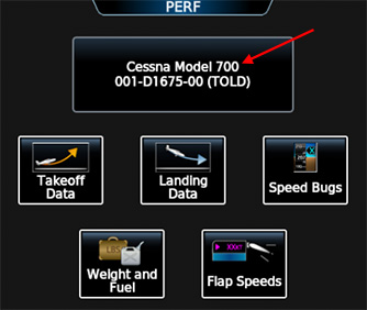
Defines the text displayed in the airframe field in the GTC PERF page. Can be safely ignored if the PERF page is not supported.
The airframe field in the GTC PERF page (red arrow):
Properties
| Scope | Inherits | Singleton | Optional |
|---|---|---|---|
<Performance> | No | Yes | Yes |
Attributes
None.
Content
String.
Default Value
<Airframe></Airframe>
<TOLD>
Defines options related to takeoff/landing (TOLD) performance calculations. The presence of this tag declares that TOLD is supported. TOLD support enables the GTC PERF page.
A full TOLD implementation requires this tag and an MFD plugin that provides a TOLD module. If this tag is present but a valid TOLD module is not provided, the GTC Takeoff and Landing Data pages will be disabled with a warning displayed on the GTC PERF page that a TOLD database could not be found.
Properties
| Scope | Inherits | Singleton | Optional |
|---|---|---|---|
<Performance> | No | Yes | Yes |
Attributes
None.
Child Tags
Default Value
None.
<Takeoff>
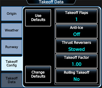
Defines options available to the user when configuring takeoff performance calculations.
An example of takeoff performance configuration options, as seen in the GTC Takeoff Data page:
Properties
| Scope | Inherits | Singleton | Optional |
|---|---|---|---|
<TOLD> | No | Yes | Yes |
Attributes
None.
Child Tags
Default Value
None.
<Landing>
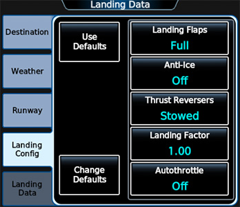
Defines options available to the user when configuring landing performance calculations.
An example of landing performance configuration options, as seen in the GTC Landing Data page:
Properties
| Scope | Inherits | Singleton | Optional |
|---|---|---|---|
<TOLD> | No | Yes | Yes |
Attributes
None.
Child Tags
Default Value
None.
<Flaps> (<TOLD>)
Defines flaps setting options available to the user when configuring takeoff/landing (TOLD) performance calculations. If this tag is omitted or defines zero options, flaps setting options will not be supported.
Properties
| Scope | Inherits | Singleton | Optional |
|---|---|---|---|
<Takeoff> or <Landing> | No | Yes | Yes |
Attributes
| Name | Value | Optional (Default) | Description |
|---|---|---|---|
| default | String | Yes ([name of first defined flaps option]) | The name of the flaps option to use as the default. |
Child Tags
Default Value
None.
<Option> ( <Flaps> (<TOLD>) )
Defines a single flaps setting option available to the user when configuring takeoff/landing (TOLD) performance calculations.
Properties
| Scope | Inherits | Singleton | Optional |
|---|---|---|---|
<Flaps> | No | No | Yes |
Attributes
| Name | Value | Optional (Default) | Description |
|---|---|---|---|
| extension | Number | No | The flaps extension angle (degrees) associated with the flaps setting option. |
Content
- String
- Declares the name of the option displayed to the user.
Default Value
None.
<AntiIce> (<TOLD>)
Declares support for the Anti-Ice option when configuring takeoff/landing (TOLD) performance calculations.
Properties
| Scope | Inherits | Singleton | Optional |
|---|---|---|---|
<Takeoff> or <Landing> | No | Yes | Yes |
Attributes
| Name | Value | Optional (Default) | Description |
|---|---|---|---|
| max‑temp | Number | Yes (∞) | The maximum temperature (degrees Celsius) at which to allow the Anti-Ice option to be set to 'On'. |
Content
None.
Default Value
None.
<ThrustReverser> (<TOLD>)
Declares support for the Thrust Reverser option when configuring takeoff/landing (TOLD) performance calculations.
Using child <Condition> tags, you can define sets of conditions which force the Thrust Reverser option to specific values. As an example, you can force the value to be 'Stowed' when runway surface conditions are dry. If two different <Condition> tags create a conflict (e.g. if one tag forces the value to 'Stowed' and the other forces the value to 'Max Reverse' under the same conditions), then the tag that appears last (in tree order) takes precedence.
Properties
| Scope | Inherits | Singleton | Optional |
|---|---|---|---|
<Takeoff> or <Landing> | No | Yes | Yes |
Attributes
None.
Child Tags
Default Value
None.
<Condition> (<ThrustReverser>)
Defines a set of conditions that forces the takeoff/landing (TOLD) performance calculation Thrust Reverser option to be restricted to a specific value or values.
Properties
| Scope | Inherits | Singleton | Optional |
|---|---|---|---|
<ThrustReverser> | No | No | Yes |
Attributes
| Name | Value | Optional (Default) | Description |
|---|---|---|---|
| surface | 'dry', 'wet', or 'contaminated' | Yes ([See Description]) | The runway surface condition required for the condition to apply. If not defined, all runway surface conditions will qualify. |
| flaps | String | Yes ([See Description]) | The name of the flaps setting required for the condition to apply. If not defined, all flaps settings will qualify. |
| anti‑ice | Boolean | Yes ([See Description]) | The value of the anti-ice setting required for the condition to apply. If not defined, all anti-ice settings will qualify. |
Content
- Boolean or 'both'
- Declares whether the Thrust Reverser setting is forced to 'Stowed' (false) or 'Max Reverse' (true) or allowed to take on both values under these conditions.
Default Value
None.
<Rolling>
Declares support for the Rolling Takeoff option when configuring takeoff performance calculations.
Properties
| Scope | Inherits | Singleton | Optional |
|---|---|---|---|
<Takeoff> | No | Yes | Yes |
Attributes
| Name | Value | Optional (Default) | Description |
|---|---|---|---|
| default | Boolean | Yes (false) | The default option value. |
Content
None.
Default Value
None.
<Autothrottle> (<Landing>)
Declares support for the Autothrottle option when configuring landing performance calculations.
Properties
| Scope | Inherits | Singleton | Optional |
|---|---|---|---|
<Landing> | No | Yes | Yes |
Attributes
None.
Content
None.
Default Value
None.
<Horizon>
Defines options related to the PFD horizon display.
Properties
| Scope | Inherits | Singleton | Optional |
|---|---|---|---|
| Global | No | Yes | Yes |
Attributes
| Name | Value | Optional (Default) | Description |
|---|---|---|---|
| symbol‑color | 'yellow' or 'white' | Yes (yellow) | The color of the symbolic aircraft. |
| director‑cue | 'single', 'dual', or 'both' | Yes (single) | The available flight director cue styles. |
| roll‑arc | Boolean | Yes (true) | Whether to render the arc on the roll scale. |
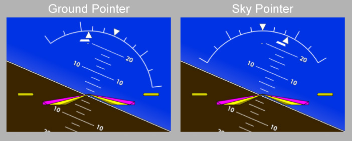
| roll‑pointer | 'sky' or 'ground' | Yes (ground) | Whether the roll indicator should be rendered with a Ground Pointer or a Sky Pointer (see below). |
| advanced‑svt | Boolean | Yes (false) | Whether advanced SVT features are supported. |
A comparison of the two different roll pointer options:
Child Tags
Default Value
<Horizon symbol-color="yellow" director-cue="single" roll-arc="true" advanced-svt="false" />
<RollLimit> (<Horizon>)
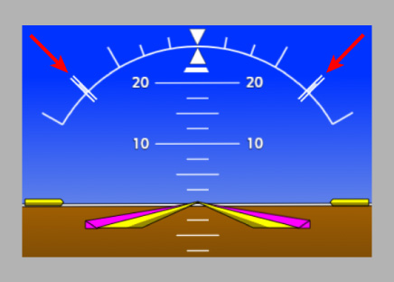
Declares support for and defines options for PFD roll limit indicators. If this tag is omitted, then the roll limit indicators will not be displayed.
The roll limit indicators (red arrows):
Properties
| Scope | Inherits | Singleton | Optional |
|---|---|---|---|
<Horizon> | No | Yes | Yes |
Attributes
None.
Child Tags
Default Value
None.
<LeftRoll> (<RollLimit>)
Defines the roll angle magnitude, in degrees, at which a left roll limit indicator should be positioned. If this tag is omitted, then the left roll limit indicator will not be displayed.
Properties
| Scope | Inherits | Singleton | Optional |
|---|---|---|---|
<RollLimit> | No | Yes | Yes |
Attributes
None.
Content
A <Number> tag, a <Bus> tag, a numeric operator on the former, or a number.
If the value evaluates to a non-finite value or NaN, then the roll limit indicator will be hidden.
Default Value
None.
<RightRoll> (<RollLimit>)
Defines the roll angle magnitude, in degrees, at which a right roll limit indicator should be positioned. If this tag is omitted, then the right roll limit indicator will not be displayed.
Properties
| Scope | Inherits | Singleton | Optional |
|---|---|---|---|
<RollLimit> | No | Yes | Yes |
Attributes
None.
Content
A <Number> tag, a <Bus> tag, a numeric operator on the former, or a number.
If the value evaluates to a non-finite value or NaN, then the roll limit indicator will be hidden.
Default Value
None.
<PitchLimit> (<Horizon>)
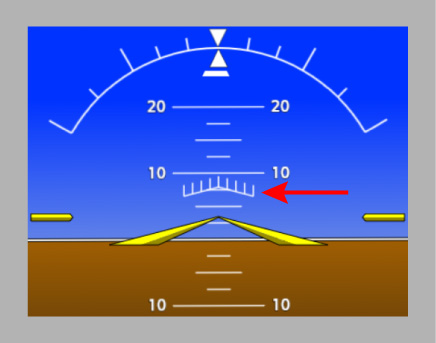
Declares support for and defines options for a PFD pitch limit indicator. If this tag is omitted, then the pitch limit indicator will not be displayed.
The (single-cue) pitch limit indicator (red arrow):
The indicator must be defined with one of the following limit types via the corresponding child tag (in order of descending precedence):
- Pitch (
<Pitch>) - Angle of attack (
<Aoa>) - Normalized angle of attack (
<NormAoa>)
If no limit type is defined, then the indicator will not be displayed.
Properties
| Scope | Inherits | Singleton | Optional |
|---|---|---|---|
<Horizon> | No | Yes | Yes |
Attributes
None.
Child Tags
Default Value
None.
<Pitch> (<PitchLimit>)
Defines the pitch angle, in degrees, at which a pitch limit indicator should be positioned. Positive values represent pitch up attitudes and negative values represent pitch down attitudes.
Properties
| Scope | Inherits | Singleton | Optional |
|---|---|---|---|
<PitchLimit> | No | Yes | Yes |
Attributes
None.
Content
A <Number> tag, a <Bus> tag, a numeric operator on the former, or a number.
If the value evaluates to a non-finite value or NaN, then the pitch limit indicator will be hidden.
Default Value
None.
<Aoa> (<PitchLimit>)
Defines the angle of attack, in degrees, at which a pitch limit indicator should be positioned.
Properties
| Scope | Inherits | Singleton | Optional |
|---|---|---|---|
<PitchLimit> | No | Yes | Yes |
Attributes
None.
Content
A <Number> tag, a <Bus> tag, a numeric operator on the former, or a number.
If the value evaluates to a non-finite value or NaN, then the pitch limit indicator will be hidden.
Default Value
None.
<NormAoa> (<PitchLimit>)
Defines the normalized angle of attack at which a pitch limit indicator should be positioned. A value of zero is equal to the zero-lift angle of attack, and a value of one is equal to the stall (critical) angle of attack.
Properties
| Scope | Inherits | Singleton | Optional |
|---|---|---|---|
<PitchLimit> | No | Yes | Yes |
Attributes
None.
Content
A <Number> tag, a <Bus> tag, a numeric operator on the former, or a number.
If the value evaluates to a non-finite value or NaN, then the pitch limit indicator will be hidden.
Default Value
None.
<ShowOffset> (<PitchLimit>)
Defines the offset of the airplane's pitch from the indicated pitch limit, in degrees, at which to show a pitch limit indicator. For example, a value of -5 will cause the indicator to be shown when the airplane's pitch is greater than or equal to the pitch limit minus 5 degrees.
Properties
| Scope | Inherits | Singleton | Optional |
|---|---|---|---|
<PitchLimit> | No | Yes | No |
Attributes
None.
Content
A <Number> tag, a <Bus> tag, a numeric operator on the former, or a number.
If the value evaluates to NaN, then the pitch limit indicator will be hidden.
<HideOffset> (<PitchLimit>)
Defines the offset of the airplane's pitch from the indicated pitch limit, in degrees, at which to hide a pitch limit indicator. For example, a value of -5 will cause the indicator to be hidden when the airplane's pitch is less than the pitch limit minus 5 degrees.
Properties
| Scope | Inherits | Singleton | Optional |
|---|---|---|---|
<PitchLimit> | No | Yes | Yes |
Attributes
None.
Content
A <Number> tag, a <Bus> tag, a numeric operator on the former, or a number.
If the value evaluates to NaN, then the pitch limit indicator will be hidden.
Default Value
A value equal to that defined for the pitch limit indicator's <ShowOffset> tag.
<AuralAlerts>
Defines aural alerts and related options.
Properties
| Scope | Inherits | Singleton | Optional |
|---|---|---|---|
| Global | No | Yes | Yes |
Attributes
| Name | Value | Optional (Default) | Description |
|---|---|---|---|
| voice | 'male', 'female', or 'both' | Yes (female) | The supported voice types for aural alerts. |
Child Tags
Default Value
<AuralAlerts voice="female"></AuralAlerts>
<Alert> (<AuralAlerts>)
Defines a single aural alert.
Properties
| Scope | Inherits | Singleton | Optional |
|---|---|---|---|
<AuralAlerts> | No | No | Yes |
Attributes
| Name | Value | Optional (Default) | Description |
|---|---|---|---|
| uuid | String | No | The ID of the alert. |
| queue | String | Yes (g3000-aural-$$xml-default$$) | The queue to assign the alert. |
| priority | Number | Yes (0) | The priority of the alert. |
| continuous | Boolean | Yes (false) | Whether the alert is continuous. |
| requeue | Boolean | Yes (false) | Whether the alert is repeating. |
Child Tags
<Sequence>- One of:
Default Value
None.
<Sequence> (<Alert>)
Defines the sound event sequence for an aural alert.
Properties
| Scope | Inherits | Singleton | Optional |
|---|---|---|---|
<Alert> | No | No | No |
Attributes
None.
Content
A comma-separated list of sound event IDs.
<Condition> (<Alert>)
Defines logic that determines when an aural alert is activated.
Properties
| Scope | Inherits | Singleton | Optional |
|---|---|---|---|
<Alert> | No | No | Yes |
Attributes
None.
Content
Logic that evaluates to a boolean (0/1) value.
Default Value
None.
<CAS> (<Alert>)
Defines a CAS alert to which to bind an aural alert's activation state.
The aural alert will be activated if and only if the CAS alert is displayed with the specified priority and optional suffix in the unacknowledged and optionally acknowledged state.
Properties
| Scope | Inherits | Singleton | Optional |
|---|---|---|---|
<Alert> | No | No | Yes |
Attributes
| Name | Value | Optional (Default) | Description |
|---|---|---|---|
| uuid | String | No | The ID of the CAS alert. |
| type | 'warning', 'caution', or 'advisory' | No | The priority type of the CAS alert. |
| suffix | String | Yes ([See description]) | The suffix of the CAS alert. If not defined, the aural alert will be bound to a CAS alert with no suffix. |
| acknowledged | Boolean | No | Whether the aural alert should be activated when the CAS alert is displayed in the acknowledged state in addition to the unacknowledged state. |
Content
None.
Default Value
None.
<Annunciations>
Defines CAS alerts.
Properties
| Scope | Inherits | Singleton | Optional |
|---|---|---|---|
| Global | No | Yes | Yes |
Attributes
None.
Child Tags
Default Value
<Annunciations></Annunciations>
<Annunciation>
Defines a single CAS alert.
Properties
| Scope | Inherits | Singleton | Optional |
|---|---|---|---|
<Annunciations> | No | No | Yes |
Attributes
None.
Child Tags
Default Value
None.
<Type> (<Annunciation>)
Defines the priority level used to activate a CAS alert.
Properties
| Scope | Inherits | Singleton | Optional |
|---|---|---|---|
<Annunciation> | No | Yes | No |
Attributes
None.
Content
'Warning', 'Caution', or 'Advisory'.
<Text> (<Annunciation>)
Defines the message text of a CAS alert.
Properties
| Scope | Inherits | Singleton | Optional |
|---|---|---|---|
<Annunciation> | No | Yes | No |
Attributes
None.
Content
String.
<Condition> (<Annunciation>)
Defines logic that determines when a CAS alert is activated.
Properties
| Scope | Inherits | Singleton | Optional |
|---|---|---|---|
<Annunciation> | No | No | No |
Attributes
| Name | Value | Optional (Default) | Description |
|---|---|---|---|
| suffix | String | Yes ([See Description]) | The suffix to activate when the condition evaluates to true. If not defined, then the alert is assumed to have no suffixes. |
Content
Logic that evaluates to a boolean (0/1) value.
<Checklist>
Defines options for the electronic checklists feature.
Properties
| Scope | Inherits | Singleton | Optional |
|---|---|---|---|
| Global | No | Yes | Yes |
Attributes
None.
Child Tags
Default Value
None.
<File> (<Checklist>)
Defines the URL path to the XML file that configures the electronic checklists feature. If this tag is not present, then the feature will be disabled.
Properties
| Scope | Inherits | Singleton | Optional |
|---|---|---|---|
<Checklist> | No | Yes | Yes |
Attributes
None.
Content
An absolute URL path.
Default Value
None.
<Iau> (<Instrument>)
Defines the index of the IAU from which this tag's parent instrument sources data.
Properties
| Scope | Inherits | Singleton | Optional |
|---|---|---|---|
| PFD, MFD, or GTC | No | Yes | Yes |
Attributes
None.
Content
Integer in range [1, ∞).
Default Value
<Iau>1</Iau>
<PfdLayout>
Defines options related to the general layout of the PFD.
Properties
| Scope | Inherits | Singleton | Optional |
|---|---|---|---|
| PFD or Global | Yes | Yes | Yes |
Attributes
| Name | Value | Optional (Default) | Description |
|---|---|---|---|
| softkeys | Boolean | Yes (false) | Whether to include softkeys. |
| instrument‑side | 'left' or 'right' | Yes (left for PFD 1; right for PFD 2) | The side of the screen on which the primary instrument display sits while the PFD is in Split mode. |
| use‑banners | Boolean | Yes (false) | Whether to use banners to display the Navigation Status Box, NAV/DME Information Box, and Wind Display. |
| use‑nav‑status‑banner | Boolean | Yes (value of use‑banners) | Whether to render the Navigation Status Box as a banner. Overrides the value of use‑banners. |
| use‑nav‑dme‑banner | Boolean | Yes (value of use‑banners) | Whether to render the NAV/DME Information Box as a banner. Overrides the value of use‑banners. |
| use‑wind‑banner | Boolean | Yes (value of use‑banners) | Whether to use banners to display the Wind Display. Overrides the value of use‑banners. |
The locations of the Navigation Status Box (red), NAV/DME Information Box (green), and Wind Display (azure) when rendered not as banners (top) and as banners (bottom). The Bearing Info Display (blue) also changes location depending on whether the Navigation Status Box is rendered as a banner:
Child Tags
Default Value
<PfdLayout softkeys="false" use-nav-status-banner="false" use-nav-dme-banner="false" use-wind-banner="false">
</PfdLayout>
<CellA>
Defines options related to the content of the PFD's Bottom Panel Cell A.
The location of Bottom Panel Cell A (orange):
Cell A can contain up to two displays. Not all combinations of displays are valid. Specifically, the time display cannot be combined with the wind display or a second instance of the time display. If an invalid combination of displays is chosen, one of the conflicting displays will be replaced with empty content and a warning message will be emitted to the console.
The time display will be rendered on the right side of the Bottom Panel if it is not included in Cell A.
Properties
| Scope | Inherits | Singleton | Optional |
|---|---|---|---|
<PfdLayout> | No | Yes | Yes |
Attributes
| Name | Value | Optional (Default) | Description |
|---|---|---|---|
| left | 'empty', 'speed', 'temperature', 'wind', or 'time' | Yes (speed) | The left-side content of Cell A. |
| right | 'empty', 'speed', 'temperature', 'wind', or 'time' | Yes (wind if wind banner is not used, temperature if wind banner is used) | The right-side content of Cell A. |
Content
None.
Default Value
<!-- If wind banner is not used. -->
<CellA left="speed" right="wind" />

<!-- If wind banner is used. -->
<CellA left="speed" right="temperature" />
<AirspeedIndicator>
Defines options related to the PFD airspeed indicator.
Properties
| Scope | Inherits | Singleton | Optional |
|---|---|---|---|
| PFD or Global | Yes | Yes | Yes |
Attributes
None.
Child Tags
<Scale><ColorRanges><BottomDisplay><TrendVector><VSpeedBugs><VSpeedAnnunc><ApproachCueBug><SpeedAlerts>
Default Value
<AirspeedIndicator></AirspeedIndicator>
<Scale> (<AirspeedIndicator>)
Defines a PFD airspeed indicator tape scale.
Properties
| Scope | Inherits | Singleton | Optional |
|---|---|---|---|
<AirspeedIndicator> | No | Yes | Yes |
Attributes
| Name | Value | Optional (Default) | Description |
|---|---|---|---|
| min | Number in range (0, ∞) | Yes (20) | The minimum tape speed (knots). |
| max | Number in range (0, ∞) | Yes (999) | The maximum tape speed (knots). |
| window | Number in range (0, ∞) | Yes (60) | The tape window (knots). |
| major‑tick‑interval | Number in range (0, ∞) | Yes (10) | The interval (knots) between major ticks. |
| minor‑tick‑factor | Integer in range [1, ∞) | Yes (2) | The number of minor ticks per major tick. |
Content
None.
Default Value
<Scale min="20" max="999" window="60" major-tick-interval="10" minor-tick-factor="2" />
<ColorRanges>
Defines color ranges for a PFD airspeed indicator tape.
Properties
| Scope | Inherits | Singleton | Optional |
|---|---|---|---|
<AirspeedIndicator> | No | Yes | Yes |
Attributes
None.
Child Tags
Default Value
<ColorRanges></ColorRanges>
<ColorRange>
Defines a single color range for a PFD airspeed indicator tape.
Properties
| Scope | Inherits | Singleton | Optional |
|---|---|---|---|
<ColorRanges> | No | No | Yes |
Attributes
| Name | Value | Optional (Default) | Description |
|---|---|---|---|
| width | 'Full' or 'Half' | No | The width of the color range. |
| color | 'Red', 'Yellow', 'White', 'Green', or 'BarberPole' | No | The color of the color range. |
Child Tags
<Minimum>- Defines the minimum speed of the color range as its content using a
<Speed>tag or a numeric operator on<Speed>tags. - If the speed value evaluates to
NaN, then the color range will be disabled.
- Defines the minimum speed of the color range as its content using a
<Maximum>- Defines the maximum speed of the color range as its content using a
<Speed>tag or a numeric operator on<Speed>tags. - If the speed value evaluates to
NaN, then the color range will be disabled.
- Defines the maximum speed of the color range as its content using a
Default Value
None.
<BottomDisplay> (<AirspeedIndicator>)
Defines how the bottom display of a PFD airspeed indicator is rendered.
Properties
| Scope | Inherits | Singleton | Optional |
|---|---|---|---|
<AirspeedIndicator> | No | Yes | Yes |
Attributes
| Name | Value | Optional (Default) | Description |
|---|---|---|---|
| mode | 'Tas' or 'Mach' | Yes (Tas) | Whether to display true airspeed or mach. |
| mach‑threshold | Number | Yes (0) | The minimum mach required for the display to be visible. Ignored if mode is not Mach. |
Content
None.
Default Value
<BottomDisplay mode="Tas" mach-threshold="0" />
<TrendVector> (<AirspeedIndicator>)
Defines how the trend vector of a PFD airspeed indicator is rendered.
Properties
| Scope | Inherits | Singleton | Optional |
|---|---|---|---|
<AirspeedIndicator> | No | Yes | Yes |
Attributes
| Name | Value | Optional (Default) | Description |
|---|---|---|---|
| lookahead | Number | Yes (6) | The lookahead time (seconds) of the trend vector. |
Content
None.
Default Value
<TrendVector lookahead="6" />
<VSpeedBugs>
Defines the V-speed bugs that appear on a PFD airspeed indicator.
The order of bugs defined in this tag affects the layering order of the rendered bugs. If a bug A is defined after bug B (in tree order), then bug A will be rendered on top of bug B when they overlap.
Properties
| Scope | Inherits | Singleton | Optional |
|---|---|---|---|
<AirspeedIndicator> | No | Yes | Yes |
Attributes
None.
Child Tags
Default Value
<VSpeedBugs></VSpeedBugs>
<Bug> (<VSpeedBugs>)
Defines a single V-speed bug that appears on a PFD airspeed indicator.
Properties
| Scope | Inherits | Singleton | Optional |
|---|---|---|---|
<VSpeedBugs> | No | No | Yes |
Attributes
| Name | Value | Optional (Default) | Description |
|---|---|---|---|
| name | String | No | The name of the V-speed displayed by the bug, as defined by a <VSpeed> tag. |
| label | String | No | The label text to display on the bug. |
| label‑color | 'Cyan', 'White', 'Green', or 'Red' | Yes (Cyan) | The color of the bug's label text. |
| label‑color‑ignore‑fms | Boolean | Yes (false) | Whether the bug's label color should not change to magenta when a FMS-computed value is used for its V-speed. |
For bugs that frequently overlap one another, you can prefix their labels with varying amounts of leading spaces to allow the label text of all bugs to be visible even when they overlap.
Content
None.
Default Value
None.
<VSpeedAnnunc>
Defines options related to V-speed annunciations for a PFD airspeed indicator.
A takeoff V-speed annunciation (image, left) is displayed when one or more takeoff V-speed bugs are not enabled, the airplane is on the ground and no landing V-speed bugs are enabled. A landing V-speed annunciation (image, right) is displayed when one or more landing V-speed bugs are not enabled, the airplane is in the air, and the FMS approach phase is active.
Properties
| Scope | Inherits | Singleton | Optional |
|---|---|---|---|
<AirspeedIndicator> | No | Yes | Yes |
Attributes
| Name | Value | Optional (Default) | Description |
|---|---|---|---|
| enabled | Boolean | Yes (true) | Whether V-speed annunciations are enabled. |
Content
None.
Default Value
<VSpeedAnnunc enabled="true" />
<ApproachCueBug>
Declares support for and defines options related to the approach cue bug for a PFD airspeed indicator.
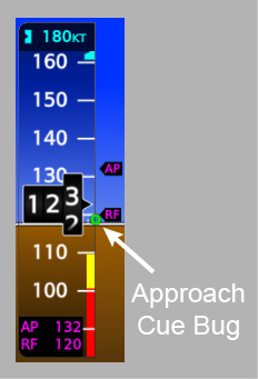
Properties
| Scope | Inherits | Singleton | Optional |
|---|---|---|---|
<AirspeedIndicator> | No | Yes | Yes |
Attributes
None.
Child Tags
Default Value
None.
<Value> (<ApproachCueBug>)
Defines the airspeed at which the approach cue bug appears on a PFD airspeed indicator.
Properties
| Scope | Inherits | Singleton | Optional |
|---|---|---|---|
<ApproachCueBug> | No | Yes | No |
Attributes
None.
Content
A <Speed> tag or a numeric operator on <Speed> tags.
If the speed value evaluates to NaN, then the approach cue bug will be disabled.
<SpeedAlerts>
Defines thresholds for overspeed and underspeed alerts on a PFD airspeed indicator.
If either the overspeed or underspeed alert threshold is not defined, then that alert will never trigger.
Properties
| Scope | Inherits | Singleton | Optional |
|---|---|---|---|
<AirspeedIndicator> | No | Yes | Yes |
Attributes
None.
Child Tags
Default Value
<SpeedAlerts></SpeedAlerts>
<Overspeed>
Defines the threshold for the overspeed alert on a PFD airspeed indicator.
Properties
| Scope | Inherits | Singleton | Optional |
|---|---|---|---|
<SpeedAlerts> | No | Yes | Yes |
Attributes
None.
Content
A <Speed> tag or a numeric operator on <Speed> tags.
If the speed value evaluates to NaN, then the overspeed alert will be disabled.
Default Value
None.
<Underspeed>
Defines the threshold for the underspeed alert on a PFD airspeed indicator.
Properties
| Scope | Inherits | Singleton | Optional |
|---|---|---|---|
<SpeedAlerts> | No | Yes | Yes |
Attributes
None.
Content
A <Speed> tag or a numeric operator on <Speed> tags.
If the speed value evaluates to NaN, then the underspeed alert will be disabled.
Default Value
None.
<Speed>
A numeric tag that defines an airspeed value.
The speed can be defined as one of several types, which determine now the numeric value of the speed is interpreted:
- Ias
- Speed is equal to the numeric value as an indicated airspeed (knots).
- Mach
- Speed is equal to the numeric value as a mach number.
- Tas
- Speed is equal to the numeric value as a true airspeed (knots).
- Reference
- Speed is equal to the sim reference speed as an indicated airspeed (knots).
- Aoa
- Speed is equal to that which produces a normalized angle of attack (where zero-lift AoA = 0 and critical AoA = 1) equal to the numeric value. If AoA cannot be accurately related to airspeed (e.g. when the airplane is on the ground or when AoA data is not available), the speed will be undefined. It is up to individual consumers of the speed value to determine how to handle an undefined airspeed.
- Bus
- Speed is equal to the value published to an event bus topic as an indicated airspeed (knots).
Use numeric operators to define speeds with complex values. For example, we can define a speed equal to the maximum operating speed of an aircraft with Vmo = 280 knots and Mmo = 0.8 as:
<Min>
  <Speed type="Ias">280</Speed>
  <Speed type="Mach">0.8</Speed>
</Min>
Properties
| Scope | Inherits | Singleton | Optional |
|---|---|---|---|
| Generic | No | N/A | N/A |
Attributes
| Name | Value | Optional (Default) | Description |
|---|---|---|---|
| type | 'Ias', 'Mach', 'Tas', 'Reference', 'Aoa', or 'Bus' | No | The type of speed. |
Content
- If
typeis Ias, Mach, Tas, or Aoa, then one of the following:- Number
- Defines the value as a constant.
<LookupTable>- Defines the value as a one-dimensional lookup table that looks it up from pressure altitude (feet).
- Number
- If
typeis Reference, then:- Sim reference speed key
- Defines the value as a sim reference speed, as defined in the
[REFERENCE SPEEDS]section offlight_model.cfg. The possible keys are:BestGlideVappVFeVmcVMaxVMinVNeVNoVrVS0VS1VxVyVyse
- Defines the value as a sim reference speed, as defined in the
- Sim reference speed key
- If
typeis Bus, then:- String
- Defines the event bus topic from which to retrieve the value (as an indicated airspeed in knots).
- String
<Altimeter>
Defines options related to the PFD airspeed indicator.
Properties
| Scope | Inherits | Singleton | Optional |
|---|---|---|---|
| PFD or Global | Yes | Yes | Yes |
Attributes
None.
Child Tags
Default Value
<Altimeter></Altimeter>
<Scale> (<Altimeter>)
Defines a PFD altimeter tape scale.
Properties
| Scope | Inherits | Singleton | Optional |
|---|---|---|---|
<Altimeter> | No | Yes | Yes |
Attributes
| Name | Value | Optional (Default) | Description |
|---|---|---|---|
| min | Number | Yes (-9999) | The minimum tape altitude (feet). |
| max | Number | Yes (99999) | The maximum tape altitude (feet). |
| window | Number in range (0, ∞) | Yes (1000) | The tape window (feet). |
| major‑tick‑interval | Number in range (0, ∞) | Yes (100) | The interval (feet) between major ticks. |
| minor‑tick‑factor | Integer in range [1, ∞) | Yes (5) | The number of minor ticks per major tick. |
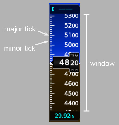
Content
None.
Default Value
<Scale min="-9999" max="99999" window="1000" major-tick-interval="100" minor-tick-factor="5" />
<TrendVector> (<Altimeter>)
Defines how the trend vector of a PFD altimeter is rendered.
Properties
| Scope | Inherits | Singleton | Optional |
|---|---|---|---|
<Altimeter> | No | Yes | Yes |
Attributes
| Name | Value | Optional (Default) | Description |
|---|---|---|---|
| lookahead | Number | Yes (6) | The lookahead time (seconds) of the trend vector. |
Content
None.
Default Value
<TrendVector lookahead="6" />
<Vsi>
Defines options related to the PFD vertical speed indicator.
Properties
| Scope | Inherits | Singleton | Optional |
|---|---|---|---|
| PFD or Global | Yes | Yes | Yes |
Attributes
None.
Child Tags
Default Value
<Vsi></Vsi>
<Scale> (<Vsi>)
Defines a PFD vertical speed indicator scale.
Properties
| Scope | Inherits | Singleton | Optional |
|---|---|---|---|
<Vsi> | No | Yes | Yes |
Attributes
| Name | Value | Optional (Default) | Description |
|---|---|---|---|
| max | Number in range (0, ∞) | Yes (4000) | The maximum nominal absolute vertical speed (feet per minute). |
| major‑tick‑interval | Number in range (0, ∞) | Yes (2000) | The interval (feet per minute) between major ticks. |
| minor‑tick‑factor | Integer in range [1, ∞) | Yes (2) | The number of minor ticks per major tick. |
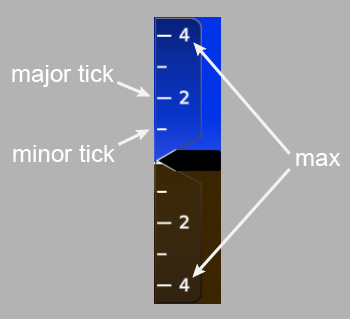
Content
None.
Default Value
<Scale max="4000" major-tick-interval="2000" minor-tick-factor="2" />
<AoaIndicator>
Defines options related to the PFD angle of attack indicator.
Properties
| Scope | Inherits | Singleton | Optional |
|---|---|---|---|
| PFD or Global | Yes | Yes | Yes |
Attributes
| Name | Value | Optional (Default) | Description |
|---|---|---|---|
| advanced | Boolean | Yes (false) | Whether to render the advanced version of the indicator. |
| readout | Boolean | Yes (false) | Whether to show the digital readout. |
| minor‑ticks | Boolean | Yes (true) | Whether to show minor tick marks. Only applies to the advanced version of the indicator. |
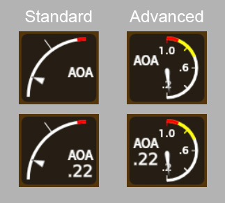
Child Tags
Default Value
<AoaIndicator advanced="false" readout="false">
</AoaIndicator>
<DonutCue> (<AoaIndicator>)
Defines the normalized angle of attack value at which the donut cue is positioned on a PFD angle of attack indicator.
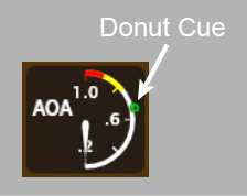
Properties
| Scope | Inherits | Singleton | Optional |
|---|---|---|---|
<AoaIndicator> | No | Yes | Yes |
Attributes
None.
Content
A <Number> tag, a <Bus> tag, or a numeric operator on the former.
If the tag's content is empty or the value evaluates to NaN, then the donut cue will be disabled.
Default Value
<DonutCue></DonutCue>
<ReferenceTick> (<AoaIndicator>)
Defines the normalized angle of attack value at which the reference tick is positioned on a PFD angle of attack indicator. The reference tick can only be displayed on the standard version of the angle of attack indicator.
Properties
| Scope | Inherits | Singleton | Optional |
|---|---|---|---|
<AoaIndicator> | No | Yes | Yes |
Attributes
None.
Content
A <Number> tag, a <Bus> tag, or a numeric operator on the former.
If the tag's content is empty or the value evaluates to NaN, then the reference tick will be disabled.
Default Value
<ReferenceTick>
  <Number>0.6</Number>
</ReferenceTick>
<Warning> (<AoaIndicator>)
Defines the normalized angle of attack warning threshold for a PFD angle of attack indicator. A red arc is displayed on the indicator from the warning threshold to the maximum normalized angle of attack (1.0). When the normalized angle of attack is in the warning range, the indicator's needle turns red and the indicator's digital readout (if one is shown) changes to red reverse video.
Properties
| Scope | Inherits | Singleton | Optional |
|---|---|---|---|
<AoaIndicator> | No | Yes | Yes |
Attributes
None.
Content
A <Number> tag, a <Bus> tag, or a numeric operator on the former.
If the tag's content is empty or the value evaluates to NaN, then the warning threshold will be disabled.
Default Value
<Warning>
  <Number>0.9</Number>
</Warning>
<Caution> (<AoaIndicator>)
Defines the normalized angle of attack caution threshold for a PFD angle of attack indicator. An amber arc is displayed on the indicator from the caution threshold to the maximum normalized angle of attack (1.0) or the warning threshold, whichever is lesser. When the normalized angle of attack is in the caution range, the indicator's needle turns amber and the indicator's digital readout (if one is shown) changes to amber reverse video.
Properties
| Scope | Inherits | Singleton | Optional |
|---|---|---|---|
<AoaIndicator> | No | Yes | Yes |
Attributes
None.
Content
A <Number> tag, a <Bus> tag, or a numeric operator on the former.
If the tag's content is empty or the value evaluates to NaN, then the caution threshold will be disabled.
Default Value
<!-- For the standard version of the AoA indicator -->
<Caution></Caution>

<!-- For the advanced version of the AoA indicator -->
<Caution>
  <Number>0.7</Number>
</Caution>
<NavStatusBox>
Defines options related to the PFD Navigation Status Box.
Properties
| Scope | Inherits | Singleton | Optional |
|---|---|---|---|
| PFD or Global | Yes | Yes | Yes |
Attributes
| Name | Value | Optional (Default) | Description |
|---|---|---|---|
| field‑1 | 'DIS', 'BRG', or 'ETE' | Yes (DIS) | The first data field to render in the box. |
| field‑2 | 'DIS', 'BRG', or 'ETE' | Yes (BRG) | The second data field to render in the box. |
Content
None.
Default Value
<NavStatusBox field-1="DIS" field-2="BRG" />
<CAS>
Declares support for and defines options related to the PFD CAS display. If this tag is omitted, then the CAS display will not be rendered on the PFD.
The location of the CAS display on the PFD (red arrow):
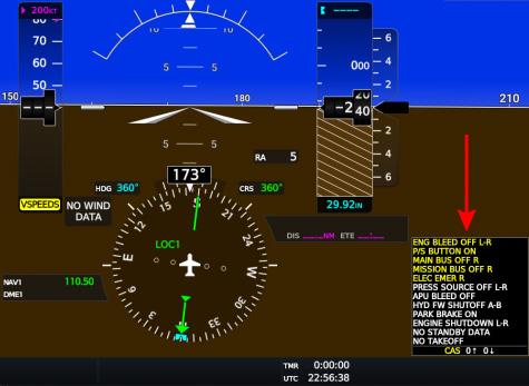
Properties
| Scope | Inherits | Singleton | Optional |
|---|---|---|---|
| PFD or Global | Yes | Yes | Yes |
Attributes
| Name | Value | Optional (Default) | Description |
|---|---|---|---|
| version | 1 or 2 | Yes (1) | The version of the CAS display to render. Version 2 supports unscrollable slots and generally has more realistic behavior. Version 1 is deprecated and is retained only for backwards compatibility. |
| full‑screen‑alert‑count | Integer in range [1, ∞) | Yes ([See Description]) | The maximum number of alerts (rows) to display while the PFD is in Full mode. Defaults to 12 if PFD softkeys are disabled and to 11 if softkeys are enabled. |
| split‑screen‑alert‑count | Integer in range [1, ∞) | Yes ([See Description]) | The maximum number of alerts (rows) to display while the PFD is in Split mode. Defaults to 12 if both PFD softkeys and the Navigation Status Box banner are disabled, to 11 if either softkeys or the banner is enabled, and to 8 if both softkeys and the banner are enabled. |
| full‑screen‑unscrollable‑alert‑count | Integer in range [1, ∞) | Yes (0) | The maximum number of unscrollable warning alerts to display while the PFD is in Full mode. Not supported by Version 1. |
| split‑screen‑unscrollable‑alert‑count | Integer in range [1, ∞) | Yes (0) | The maximum number of unscrollable warning alerts to display while the PFD is in Split mode. Not supported by Version 1. |
Content
None.
Default Value
None.
<StartupScreen>
Declares support for and defines options related to the MFD startup screen. If this tag is omitted, then the startup screen will not be shown.
The following image shows an example of a startup screen:
The startup screen requires softkey support to function correctly. Do not include the startup screen if your airplane does not have softkeys for the MFD.
Properties
| Scope | Inherits | Singleton | Optional |
|---|---|---|---|
| MFD | No | Yes | Yes |
Attributes
| Name | Value | Optional (Default) | Description |
|---|---|---|---|
| airplane | String | Yes ("") | The airplane name to display on the startup screen in the System row. |
| logo‑src | String | Yes ([None]) | The absolute path of the image file to display as the startup screen logo. If omitted, then no logo will be displayed. |
Content
None.
Default Value
None.
<GtcConfig>
Defines configuration options for a GTC.
Properties
| Scope | Inherits | Singleton | Optional |
|---|---|---|---|
| GTC | No | Yes | No |
Attributes
| Name | Value | Optional (Default) | Description |
|---|---|---|---|
| orientation | 'horizontal' or 'vertical' | No | The orientation of the GTC. |
| control‑setup | If horizontal: 'all' or 'pfd‑navcom'. If vertical: 'pfd' or 'mfd'. | No | The control modes supported by the GTC. |
| default‑control‑mode | 'pfd', 'mfd', or 'navcom' | Yes ([See Description]) | The default control mode to which the GTC initializes on power-up. If not defined, then the option will default to the first supported control mode in the following order: 'pfd', 'mfd', 'navcom'. |
| pfd‑control‑index | '1' or '2' | See Description | The index of the PFD controlled by the GTC. Required if and only if the PFD control mode is supported. |
| pane‑control‑side | 'left' or 'right' | See Description | Whether this is the left (cyan) or right (purple) display pane controlling GTC. Required if and only if the MFD control mode is supported. |
Content
None.
<LookupTable>
Defines an N-dimensional linearly interpolated lookup table.
Properties
| Scope | Inherits | Singleton | Optional |
|---|---|---|---|
| Generic | No | N/A | N/A |
Attributes
| Name | Value | Optional (Default) | Description |
|---|---|---|---|
| dimensions | Integer in range [1, ∞) | No | The table's dimension count. |
Content
An array of breakpoints, in standard JSON format. Each breakpoint is a number array of length dimensions + 1, where the value at index 0 is the breakpoint output, and the values at indexes i = 1...dimension are the breakpoint inputs in each dimension i.
<Number>
A numeric tag that defines a constant.
Properties
| Scope | Inherits | Singleton | Optional |
|---|---|---|---|
| Generic | No | N/A | N/A |
Attributes
None.
Content
A number.
<Bus>
A numeric tag that defines a value derived from an event bus topic.
Properties
| Scope | Inherits | Singleton | Optional |
|---|---|---|---|
| Generic | No | N/A | N/A |
Attributes
None.
Content
An event bus topic name. The tag's value will be bound to the data published to this topic. If no data is published to the topic, the tag's value will be equal to NaN.
Ensure that only data of type number are published to the specified event bus topic.