DirectX-Specs
DirectX Raytracing (DXR) Functional Spec, Part 2
v0.29 7/3/2026
Contents
- Intro
- Clustered geometry
- Partitioned Top Level Acceleration Structures
- Indirect Acceleration Structure operations
- API
- Device methods
- Command list methods
- ExecuteIndirectRTASOperations
- ExecuteIndirectRTASOperations Structures
- D3D12_EXECUTE_INDIRECT_RTAS_OPERATIONS_FLAGS
- D3D12_RTAS_OPERATION_DESC
- D3D12_RTAS_OPERATION_INPUTS
- D3D12_RTAS_OPERATION_TYPE
- Navigating RTAS operation types
- D3D12_RTAS_TOOLS_VISUALIZATION_BUILD_INPUTS_HEADER
- D3D12_RTAS_CLUSTER_LIMITS
- D3D12_RTAS_CLUSTER_TRIANGLES_INPUTS_DESC
- D3D12_RTAS_CLUSTER_TEMPLATE_TRIANGLES_INPUTS_DESC
- D3D12_RTAS_INSTANTIATE_CLUSTER_TEMPLATE_INPUTS_DESC
- Template instance format conversion semantics
- The role of geometry index in a cluster
- D3D12_RTAS_OPERATION_FLAGS
- D3D12_RTAS_OPERATION_MODE
- Implicit vs explicit destinations for acceleration structure operations
- Why compaction doesn’t apply to clustered geometry
- Resource state for read-only arguments
- Resource state for read-write or write-only arguments
- Resource state for acceleration structures
- D3D12_VERTEX_FORMAT
- D3D12_INDEX_FORMAT
- D3D12_RTAS_CLUSTER_MOVE_OPERATION_FLAGS
- D3D12_RTAS_MOVE_OPERATION_TYPE
- D3D12_RTAS_CLAS_INPUTS_DESC
- D3D12_RTAS_CLUSTER_MOVES_DESC
- D3D12_RTAS_BATCHED_OPERATION_DATA
- D3D12_RTAS_OPERATION_ADDRESS_RESOLUTION_FLAGS
- D3D12_RTAS_PARTITIONED_TLAS_INPUTS_DESC
- D3D12_RTAS_PARTITIONED_TLAS_FLAGS
- D3D12_RTAS_PARTITIONED_TLAS_OPERATION_DATA
- PTLAS resizing
- ExecuteIndirectRTASOperations GPU-side Argument Structures
- D3D12_RTAS_CLUSTER_OPERATION_CLAS_FLAGS
- D3D12_RTAS_CLUSTERED_GEOMETRY_FLAGS
- D3D12_RTAS_OPERATION_BUILD_CLAS_FROM_TRIANGLES_ARGS
- D3D12_RTAS_OPERATION_BUILD_BLAS_FROM_CLAS_ARGS
- D3D12_RTAS_OPERATION_MOVE_CLUSTER_OBJECTS_ARGS
- D3D12_RTAS_OPERATION_BUILD_CLUSTER_TEMPLATES_FROM_TRIANGLES_ARGS
- D3D12_VERTEX_FORMAT_COMPRESSED1_TEMPLATE_HEADER
- Compressed1 bitfield helper macros
- D3D12_RTAS_OPERATION_INSTANTIATE_CLUSTER_TEMPLATES_ARGS
- D3D12_RTAS_PARTITIONED_TLAS_OPERATION
- D3D12_RTAS_PARTITIONED_TLAS_OPERATION_TYPE
- D3D12_RTAS_PARTITIONED_TLAS_OPERATION_WRITE_INSTANCE_ARGS
- D3D12_RTAS_PARTITIONED_TLAS_OPERATION_UPDATE_INSTANCE_ARGS
- D3D12_RTAS_PARTITIONED_TLAS_OPERATION_TRANSLATE_PARTITION_ARGS
- Instance writes or updates and partition translation updates in the same build
- D3D12_RTAS_PARTITIONED_TLAS_PARTITION_INDEX
- D3D12_RTAS_PARTITIONED_TLAS_INSTANCE_FLAGS
- ExecuteIndirectRTASOperations Structures
- ExecuteIndirectRTASOperations
- Constants
- HLSL
- Potential future features
- Change Log
Intro
This is a continuation of the large original raytracing spec: raytracing.md into a second file. See the walkthrough there for a listing of prior features.
Features defined here:
- Clustered Geometry
- Partitioned Top Level Acceleration Structures
- Indirect Acceleration Structure Operations
The focus is using finer grained building blocks for more efficient raytracing acceleration structure management builds and updates. In contrast to the original raytracing API, these operations are also now GPU-driven. This set of features can work well on any hardware with existing raytracing support given a driver update. Newer hardware may show some additional improvements while developers can deploy the same code and assets broadly. If some older devices don’t get support it will likely be a resourcing tradeoff the hardware vendor needed to make.
Support is reported by ClustersAndPTLASSupported in D3D12_FEATURE_OPTIONS_NNN (version NNN determined at ship) via CheckFeatureSupport(). This also implies support for Shader Model 6.10 with the small HLSL portion of these features. Shader Model 6.10 also requires TriangleObjectPositions support, which a device could expose on its own without the above features.
There is a D3D12_RAYTRACING_TIER_2_0 which requires all of the above, in addition to all features from previous tiers. Some D3D12_RAYTRACING_TIER_1_1 hardware may support the feature caps described above, given they only require driver update, but not support Opacity Micromaps required with D3D12_RAYTRACING_TIER_1_2+.
These features are currently being developed. Release likely starts with a ~late summer 2026 preview. The spec is posted early given the features are aligned across hardware vendors, still subject to refinement before shipping.
The small HLSL parts are also published as proposals already: HLSL support for Clustered Geometry in Raytracing and HLSL TriangleObjectPositions.
Clustered geometry
Acceleration structure build times can become a bottleneck in raytracing applications that require large amounts of dynamic geometry. Example scenarios include new geometry being streamed in from disk, high numbers of animated objects, level-of-detail systems, or dynamic tessellation.
Clustered Geometry addresses this issue by enabling apps to build acceleration structures around compact clusters of primitives and use those as building blocks to construct bottom-level acceleration structures. This division of labor results in significantly faster acceleration structure build times compared to starting from triangle soup.
Apps can also save memory reusing clusters, such as across different LODs that combine sets of clusters. Certain geometry processing pipelines already prepare such clusters, for instance as meshlets for use with mesh shaders.
Clustered Geometry consists of two concepts:
- An acceleration structure level referred to as Cluster Level Acceleration Structure (or CLAS).
- An alternative structure to a BLAS, referred to as the Cluster BLAS. A Cluster BLAS is a BLAS constructed from the aforementioned CLAS structures.
A CLAS is a type of acceleration structure that functions as an intermediate primitive, itself constructed from triangles, from which Clustered Bottom Level Acceleration Structures (Cluster BLAS) can be constructed. The Cluster BLAS is an alternative for Bottom Level Acceleration Structures. The intent is for an application to group the geometry in their meshes into CLAS primitives before generating the Cluster BLAS from them. In order to maintain good trace performance, the application should group primitives into clusters based on spatial proximity.
The diagram below shows a comparison of how a Cluster BLAS versus a traditional BLAS would fit into a TLAS.
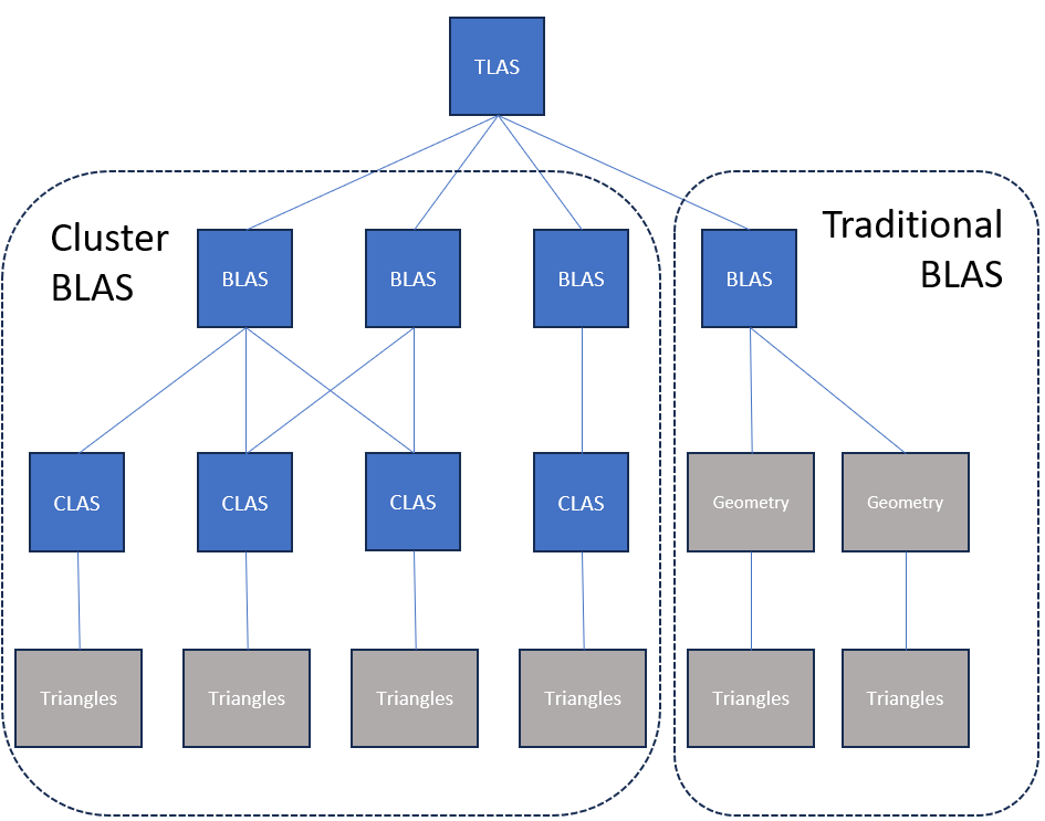
A Cluster BLAS behaves identically to an existing BLAS except as follows:
- Calls to CopyRaytracingAccelerationStructure and EmitRaytracingAccelerationStructurePostbuildInfo are not supported, except for the serialize/deserialize and tools-visualization modes documented in the base spec: specifically
D3D12_RAYTRACING_ACCELERATION_STRUCTURE_COPY_MODE_SERIALIZE,_DESERIALIZE, and_VISUALIZATION_DECODE_FOR_TOOLS, along with the correspondingD3D12_RAYTRACING_ACCELERATION_STRUCTURE_POSTBUILD_INFO_SERIALIZATIONand_TOOLS_VISUALIZATIONpostbuild-info types used to size their outputs. Compaction and clone copy modes are not supported;D3D12_RTAS_OPERATION_TYPE_MOVE_CLUSTER_OBJECTSshould be used to copy/move these objects. For Cluster BLAS in_SERIALIZEor_VISUALIZATION_DECODE_FOR_TOOLS, and for corresponding postbuild sizing queries, all referenced CLAS must be valid for the duration of the operation on the GPU timeline. This does not constrain deserialization order semantics, which remain as defined by the base serialization/deserialization behavior. - Cluster BLAS cannot be used as source acceleration structures for calls to BuildRaytracingAccelerationStructure. Cluster Templates cover this functionality.
- Cluster BLAS contain explicit references to the CLAS they were constructed from. If CLAS are moved or become invalid then any Cluster BLAS referencing them will likewise become invalid.
In all other situations, any reference to a BLAS can be substituted with a Cluster BLAS without loss of functionality.
Accessing acceleration structures that may contain clusters from shaders requires opting in via D3D12_RAYTRACING_PIPELINE_FLAG_ALLOW_CLUSTERED_GEOMETRY flag for the state object, or for RayQuery, RAYQUERY_FLAG_ALLOW_CLUSTERED_GEOMETRY in the RayQuery instantiation.
Because the application can group primitives into independent clusters, the creation of which is usually amortized over many frames, the time spent building acceleration structures is reduced dramatically. Memory usage and build time are further improved if CLAS can be reused (referenced) across multiple Cluster BLAS. Note that this is a fundamental difference to traditional BLAS, where all input primitive information is stored in the BLAS itself. An application might use this for seamless streaming or level of detail systems, where CLAS of different geometric densities are dynamically combined into a single BLAS.
All operations related to cluster geometry are provided as part of a flexible indirect acceleration structure operations API. This allows applications to generate CLAS geometry, construct Cluster BLAS from lists of CLAS, and move or copy CLAS and Cluster BLAS. The inputs to the call are sourced from device memory rather than host memory and operate on many elements at once, thus avoiding the majority of host-side cost associated with existing acceleration structure functions.
Cluster level acceleration structure
A CLAS behaves like a BLAS in many ways but with the following differences:
- CLAS can only contain a limited number of triangles and vertices. The limit is 256 triangles and 256 vertices, one cluster per CLAS.
- CLAS cannot be directly included in a TLAS; instead a Cluster BLAS needs to be created from one or more CLAS to trace the geometry within a CLAS.
- Geometry Indices in a CLAS can be specified per-primitive and may be non-consecutive. See The role of geometry index in a cluster.
- A CLAS can be assigned a user determined 32-bit ClusterID that can be fetched from a hit shader, intended to be used to fetch attributes among other purposes.
- Cluster BLAS primitive indices are limited to the CLAS being hit, and thus limited to a range from 0 to 255. To identify which CLAS within a Cluster BLAS is hit, the ClusterID is intended to be used.
When creating a BLAS out of a set of CLAS, the resulting BLAS contains references to the source CLAS structures. Therefore, modifying any of the source CLAS after constructing a BLAS invalidates the BLAS and makes it invalid to trace or use as input in any other function call. These Cluster BLAS objects created from CLAS can be added to existing TLAS or Partitioned TLAS objects. With Cluster BLAS, triangle indices are no longer unique within the BLAS. Instead, the application needs to use the ClusterID HLSL intrinsic in the hit shader to identify which CLAS was hit.
Cluster BLAS objects are not compatible with BuildRaytracingAccelerationStructure(). They are also not compatible with CopyRaytracingAccelerationStructure() and EmitRaytracingAccelerationStructurePostbuildInfo(), except for the serialize/deserialize and tools-visualization modes: D3D12_RAYTRACING_ACCELERATION_STRUCTURE_COPY_MODE_SERIALIZE, _DESERIALIZE, and _VISUALIZATION_DECODE_FOR_TOOLS, plus the corresponding POSTBUILD_INFO_SERIALIZATION and _TOOLS_VISUALIZATION postbuild-info types used to size their outputs. For Cluster BLAS in _SERIALIZE or _VISUALIZATION_DECODE_FOR_TOOLS, and for corresponding postbuild sizing queries, all referenced CLAS must be valid for the duration of the operation on the GPU timeline. This does not constrain deserialization order semantics, which remain as defined by the base serialization/deserialization behavior.
Instead, all cluster-level acceleration structure functionality is provided through GPU-driven indirect acceleration structure operations. In particular ExecuteIndirectRTASOperations() must be used to perform various tasks such as builds, fetching sizes and copying.
The intended use for cluster-related operations is for the user to create BLAS objects out of CLAS objects. This provides the following advantages to the user:
- CLAS allow reusing of geometry data between multiple BLAS, reducing memory footprint.
- CLAS can be built efficiently in general, and using template-based instantiation CLAS can be created with extremely low overhead.
- CLAS/Cluster BLAS require no compaction and can be emitted without unnecessary structures within the object. See Why compaction doesn’t apply to clustered geometry.
- Constructing BLAS from CLAS is more efficient by reducing the number of primitives the build operates on. For assembling BLAS out of CLAS of 100 triangles a ~100x speedup is reasonable to expect.
- Non-consecutive geometry indexing allows more flexible use of Shader Tables.
- All operations are device driven and allow device-generated arguments.
This allows users to create higher fidelity BLAS that can be more efficiently adapted to both animation (cluster template instantiation) and level of detail changes.
CLAS allow the user to set the Geometry Index explicitly for each triangle through a buffer which then gets added to a base index provided for the entire CLAS.
CLAS come with built-in support for Opacity Micromaps, and CLAS utilizing Opacity Micromaps and different Geometry Flags can freely be mixed into a single Cluster BLAS.
See Navigating RTAS operation types.
Cluster templates
In addition to CLAS and Cluster BLAS, a third structure is introduced referred to as Cluster Template. A Cluster Template is a partially constructed CLAS with the following properties compared to a CLAS:
- No Vertex Positions
- Optional example positions can be specified as a hint about where instantiated vertices might be. These are discarded in the resulting template. Useful for animated meshes, not that useful for tessellation / dynamic mesh generation. Instantiating templates always provides final positions for a CLAS build.
- Reduced size due to lack of position information
- No ability to trace or be used to build other acceleration structures
- Optimized for ability to be used to efficiently instantiate a CLAS when provided vertex data
- Same content relating to other non-positional properties as a CLAS, which will be inherited by the CLAS when instantiated
- Ability to provide hints to optimize Cluster Templates for certain instantiation positions, permitting different trade-offs between flexibility and trace performance
These Cluster Template objects can be used to efficiently instantiate CLAS in memory. Instantiated CLAS from the same Cluster Template only differ by vertex positions, ClusterID and a uniform geometry index offset. Cluster Templates front-load as much computation as can be made position invariant of the CLAS creation so that its results can be reused when creating multiple CLAS. See Template instance format conversion semantics for details on how vertex data is handled during instantiation.
The image below shows how a Cluster Template is instantiated compared with a direct build of a CLAS:
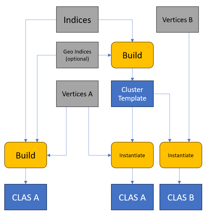
When creating a Cluster Template, Geometry Indices can be controlled the same way as when building a CLAS directly. When instantiating a Cluster Template, an additional base offset added to all Geometry Indices in the CLAS can be provided. The final Geometry Indices cannot exceed the Maximum Geometry Index declared when creating the Cluster Template.
An example use of Cluster Templates is for animated objects in their scenes with the following workflow:
- Create Cluster Templates for the clusters of a mesh that the app intends to animate when the mesh is streamed in
- For each frame with instances of this mesh being animated:
- Use a compute shader to generate the animated vertex positions for each instance of the mesh
- Instantiate the Cluster Templates to produce the per-instance CLAS from the Cluster Templates created during stream-in and the per-instance vertex positions.
- Create a BLAS over these clusters and then use the resulting Cluster BLAS as usual with a user determined ClusterID encoding to fetch per-instance and per-mesh properties
Other use cases could include repeatedly instantiating pre-generated patterns for particles or surfaces of dynamically created geometry.
This workflow is intended to provide performance comparable with traditional refit while permitting:
- Topology changes of the animated mesh without additional cost by swapping out Cluster Templates.
- Lower memory usage as:
- Information for refitting is only stored in templates and shared by all instances.
- Templates support more compression features than traditional BLAS.
- Better trace performance as the resulting BLAS can be recreated efficiently every frame and adapt to the shape of the object.
- Paying animation cost only for parts of an object that is animated, allowing static parts (for example trunk of a tree) to be encoded in their own CLAS and shared between all instances, without requiring separate overlapping instances and the associated trace penalties.
Overall, cluster templates are intended to be an upgrade versus traditional updates / refits, that is both more efficient and works better with indirect/device-based workflows.
See Navigating RTAS operation types.
Cluster input geometry encoding
Vertex position input to cluster builds supports the same uncompressed input formats supported for triangle geometries in plain BLAS.
In addition, cluster build supports a compressed position format. The benefit to an app for using this format is that the input data to cluster build can take less space, with the possibility that some savings propagate to the hardware’s BVH in some form as well with reasonable BVH build times. This is particularly true if the app is able to represent its source assets in the same or similar format as the compressed format described here so that it doesn’t have to spend much effort of its own transcoding to this format. It is simply a flexible fixed-point position encoding which should be natural for many engines to choose, at least for some portion of geometry assets.
The VertexFormat fields in the CPU-side structs D3D12_RTAS_CLUSTER_TRIANGLES_INPUTS_DESC, D3D12_RTAS_CLUSTER_TEMPLATE_TRIANGLES_INPUTS_DESC and D3D12_RTAS_INSTANTIATE_CLUSTER_TEMPLATE_INPUTS_DESC have a dedicated enum type D3D12_VERTEX_FORMAT which lists the various supported vertex formats. Most of these are similar to existing DXGI_FORMAT_* - the subset that work for plain BLAS as mentioned above.
The reason for a new enum is both to be more clear about the exact set of supported formats, and to include the option of compressed vertex formats in the list which aren’t worth adding to the general purpose DXGI_FORMAT enum. The one compressed encoding defined so far is defined further below - Compressed1 position encoding.
Topology input to cluster builds must be indexed triangle lists. Index format is chosen by the IndexFormat (D3D12_INDEX_FORMAT) member in GPU-side structures D3D12_RTAS_OPERATION_BUILD_CLAS_FROM_TRIANGLES_ARGS or D3D12_RTAS_OPERATION_BUILD_CLUSTER_TEMPLATES_FROM_TRIANGLES_ARGS.
Compressed1 position encoding
D3D12_VERTEX_FORMAT_COMPRESSED1 vertices are encoded in the following format with no padding between sections. These are pointed to by GPU-side cluster build arguments and cluster build from template arguments:
(1) Header (2) Vertex block
In detail:
(1) Header for entire set of cluster’s vertex data (12 bytes)
- 4 byte aligned start address
- Power of 2 exponent value encoding a value in range
[-126..105](biased range[1..232])- Validity constraints and undefined behavior are defined in COMPRESSED1 finite float32 requirement.
- 24bit * 3 (xyz) anchor position encoding
- Bit sizes for per-vertex xyz deltas from anchor (specifying
1-16bits per component)
Note vertex count isn’t needed here as it is part of the overall cluster description. See
VertexCountin GPU-side build arguments: D3D12_RTAS_OPERATION_BUILD_CLAS_FROM_TRIANGLES_ARGS and D3D12_RTAS_OPERATION_BUILD_CLUSTER_TEMPLATES_FROM_TRIANGLES_ARGS. Also see theMax*counts in CPU-side build inputs description:D3D12_RTAS_CLUSTER_LIMITS.
// D3D12_VERTEX_FORMAT_COMPRESSED1_HEADER bit assignments:
//
// field0:
//  [07:00] exponent   - Float32 scale (exponent-only) with bias 127.
//                       Stored biased range: [1..232] (actual exponent range: [-126..105]).
//                       Must add 127 to the actual exponent before encoding.
//                       Must subtract 127 after decoding to get the actual exponent.
//  [31:08] x_anchor   - 24-bit signed two's complement.
//                       0x800000 represents -8,388,608.
//
// field1:
//  [03:00] x_bits     - Component bit count for x, stored as (count - 1).
//                       Must subtract 1 from the actual bit count before encoding.
//                       Must add 1 after decoding to get the actual bit count (1-16).
//  [07:04] y_bits     - Component bit count for y, stored as (count - 1). Same bias as x_bits.
//  [31:08] y_anchor   - 24-bit signed two's complement.
//
// field2:
//  [03:00] z_bits     - Component bit count for z, stored as (count - 1). Same bias as x_bits.
//  [07:04] unused
//  [31:08] z_anchor   - 24-bit signed two's complement.

typedef struct D3D12_VERTEX_FORMAT_COMPRESSED1_HEADER
{
    UINT field0;
    UINT field1;
    UINT field2;
} D3D12_VERTEX_FORMAT_COMPRESSED1_HEADER;
The fields within this struct are packed into plain UINT members rather than C++ bitfields in order to guarantee portable layout across C++ compilers, architectures, and HLSL. Helper encode/decode macros are provided in d3d12.h for accessing individual fields that also work in HLSL. See Compressed1 bitfield helper macros.
(2) Vertex block
- Directly after the header
- Per vertex xyz deltas relative to the cluster’s anchor in the header
- Bit widths for each of x, y and z come from the header
A position is decoded as:
float3 compressed1_position_decode(int24_t Anchor[3], uint16_t Offset[3], uint8_t Exponent)
{
    int x = Anchor[0] + Offset[0]; // 24b + 16b add.. 25b result
    int y = Anchor[1] + Offset[1];
    int z = Anchor[2] + Offset[2];

    float fx = (float)(x); // convert results to float
    float fy = (float)(y);
    float fz = (float)(z);

    // apply a pow2 scale factor
    float scale = ldexp(1.0f, Exponent - 127);
    return float3(fx, fy, fz) * scale;
}
COMPRESSED1 finite float32 requirement
For each component in Compressed1 position encoding, define I = Anchor + Offset, where:
Anchoris signed 24-bit two’s complement:[-8,388,608 .. 8,388,607]Offsetis an unsignedn-bit value,nin[1..16]:[0 .. (2^n - 1)]eis the biased exponent in theCOMPRESSED1header
COMPRESSED1 values are valid if:
e in [1..232]- If
e = 232,I in [-8,388,607 .. 8,388,607]
For e in [1..231], I has no additional restriction beyond the encoded range implied by Anchor and Offset.
Any other case is outside this specification and invokes undefined behavior. Implementations are not required to clamp or repair invalid values.
Compressed1 with cluster templates
When generating cluster templates, D3D12_RTAS_CLUSTER_TEMPLATE_TRIANGLES_INPUTS_DESC has a VertexInstantiationFormat member that specifies the data format that instances of the template will store in the acceleration structure. Actual hardware implementation may vary, but it will functionally appear as if the specified format is what is used.
If this format is D3D12_VERTEX_FORMAT_COMPRESSED1, then D3D12_RTAS_OPERATION_BUILD_CLUSTER_TEMPLATES_FROM_TRIANGLES_ARGS has a D3D12_VERTEX_FORMAT_COMPRESSED1_TEMPLATE_HEADER Compressed1TemplateHeader field that specifies a subset of the full COMPRESSED1 header that is locked for all instances of the template: exponent, x_bits, y_bits and z_bits.
The anchor is derived at template instantiation by the min x, y and z components of all the input positions. The combination of fixed template properties and derived anchor define the format that the input positions are encoded with at template instantiation.
The exception is if the input vertex data at template instantiation also happens to be in COMPRESSED1 format and its header specifies x_bits, y_bits and z_bits less than or equal to the values in the template. In this case the anchor doesn’t have to be derived. It can just be taken from the input header, and the input bitstream can also be taken as-is (padding extra bits with 0). And in this case the exponent is also taken from the input header as well, so the exponent in the template’s Compressed1TemplateHeader is ignored.
See Template instance format conversion semantics.
Since COMPRESSED1 templates lock the exponent, x_bits, y_bits and z_bits properties, adjacent clusters instantiated with the same template can remain watertight (no cracks between adjacent geometry) even when there is animation of the vertices input to each cluster’s template instantiation.
For template instantiation to COMPRESSED1 (any source format other than the COMPRESSED1-source compatibility exception described above), input positions are quantized per the rules in Conversion to COMPRESSED1 under Template instance format conversion semantics. Summarizing for context here: define s = 2^(e-127) from the locked biased exponent e, then per component I = round(V / s) (rounding mode defined there). The anchor is derived per component as min(I) over the already-quantized integer values across all input vertices; per-vertex offsets are then I - Anchor in integer space. Because the anchor is selected from the quantized set rather than rounded independently, the vertex that determined the anchor naturally encodes to an offset of exactly 0.
The encoder must keep the resulting values within the format’s storage budget per component c:
min(I_c)in[-8,388,608 .. +8,388,607]so the anchor fits the 24-bit signedAnchor_cfield.max(I_c) - min(I_c) <= 2^(n_c) - 1so every offset fits then_c-bit unsignedOffset_cfield. Sincen_c(x_bits,y_bits,z_bits) is locked in the template header, the input position spread per cluster must fit within the locked bit budget.
Validity and undefined behavior for the resulting COMPRESSED1 values are defined in COMPRESSED1 finite float32 requirement.
Even in the exception case described above, which is instantiating COMPRESSED1 templates with COMPRESSED1 input data with bit counts less than or equal to the Compressed1TemplateHeader, where anchor and exponent are taken directly from the input header, watertightness across neighboring clusters can be achieved by the app.
This requires careful selection of anchor and exponent values in the input COMPRESSED1 headers for adjacent clusters to result in effectively the same decoded data for vertices shared across clusters (possible with care even if they use different exponent values). This is true for non-templates as well.
Partitioned Top Level Acceleration Structures
As developers strive to create larger and more detailed worlds, instance counts have been steadily increasing since the launch of DXR. The design of the Top Level Acceleration Structure API requires the entire data structure to be rebuilt even if only a small number of instances are modified. This does not allow for exploiting temporal invariance across frames, such as in applications where the majority of the scene is static.
Partitioned Top Level Acceleration Structures (PTLAS) provide an alternative to Top Level Acceleration Structures (TLAS). Unlike TLAS, PTLAS allows the efficient reuse of previously built parts of the acceleration structure, therefore significantly increasing build performance and enabling higher overall instance counts. From the perspective of ray tracing shaders and pipelines, PTLAS behavior is identical to existing TLAS.
Partitioned TLAS overview
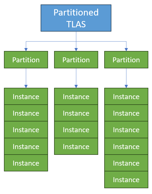
The primary difference between a Partitioned TLAS and a non-Partitioned TLAS is the partitioning of instances, as the name implies. A PTLAS build is internally split into two stages:
- an acceleration structure for each partition, combining the instances within the partition into a single acceleration structure.
- a second type of acceleration structure that combines all the partitions into a single acceleration structure equivalent to a TLAS.
The following depicts the arrangement of the acceleration structures within a Partitioned TLAS:
The Partitioned TLAS API has the following key design properties:
- The structure manages a persistent acceleration structure that may be rebuilt partially by modifying some partitions but not others.
- Rebuilds are usually expected to be performed in-place, although this is not mandatory.
- The structure manages a persistent instance list that is separate from the instances that are actually enabled (visible to rays). To control which instances are enabled, the user assigns them to one of several partitions.
- There exists a single special partition referred to as the global partition. Instances assigned to the global partition behave (in terms of performance) as if each was in a partition of its own. Typical use cases for the global partition include dynamic instances that move every frame, such as characters in a game.
- Instances can be assigned an explicit bounding box, allowing their BLAS pointer to be replaced without the cost of a rebuild. This particularly facilitates LOD techniques, where objects of which the conservative common bounds are known are swapped out against each other.
- Partitions may be assigned a translation vector that can be updated efficiently while otherwise retaining the contents of the partition. This is particularly useful for applications that periodically re-center the scene around the origin to avoid floating point precision issues.
- Arguments to the PTLAS build call are provided indirectly (in GPU memory).
- No changes or additions to the shading language are required.
Applications will benefit most from the performance improvements offered by PTLAS when instances and partitions are carefully organized. Spatial overlap between partition bounds will have a negative effect on trace performance on most implementations, similar to instance overlap in existing TLAS. Generally small partitions (100-1000 instances) should offer the majority of build speed improvements with the smallest trace performance impact. The PTLAS structure itself, with optimally chosen partitions approximating ideal BVH subtrees, should have negligible trace performance impact.
PTLAS are not compatible with BuildRaytracingAccelerationStructure(). They are also not compatible with CopyRaytracingAccelerationStructure() and EmitRaytracingAccelerationStructurePostbuildInfo(), except for the serialize/deserialize and tools-visualization modes: D3D12_RAYTRACING_ACCELERATION_STRUCTURE_COPY_MODE_SERIALIZE, _DESERIALIZE, and _VISUALIZATION_DECODE_FOR_TOOLS, plus the corresponding POSTBUILD_INFO_SERIALIZATION and _TOOLS_VISUALIZATION postbuild-info types used to size their outputs.
Instead, just like with CLAS, all PTLAS related functionality is provided through GPU-driven indirect acceleration structure operations. ExecuteIndirectRTASOperations() must be used to perform various tasks such as builds and fetching sizes.
See Navigating RTAS operation types.
Also see PTLAS resizing.
Global partition
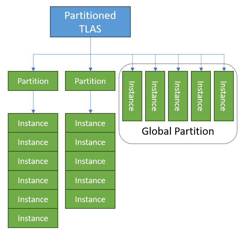
Partitioned TLAS supports a special Global Partition that exists separately from the other partitions. Instances can be assigned to the Global Partition in the same way they can be assigned to other partitions. The Global Partition differs in two ways from other partitions:
- It has a separate size limit that can be set independently from other partitions.
- When the internal Partitioned TLAS acceleration structures are built, the instances within the global partition are individually inserted into the second-stage acceleration structure that combines all partitions. Therefore, the instances within the Global Partition behave (in terms of trace performance and build performance) as if each was within its own partition, but without inflating the maximum partition count.
This diagram compares instances in the Global Partition with instances in ordinary partitions within the Partitioned TLAS:
The intended use of the Global Partition is for applications to use it for instances that are expected to frequently require updates (for example: animated characters in motion). Placing these instances in the global partition reduces the build cost that potentially modifying many individual partitions would cause while eliminating the trace performance impact that having them in a larger spatially overlapping partition would cause.
Instances within the global partition still have a build performance impact, and once instances have settled and it is expected they won’t require frequent transform updates, it is recommended to write them into a spatially well-located, non-global partition instead.
Partition translation
In order to assist titles with large worlds that require more precision than 32-bit floating point numbers can provide, the Partitioned TLAS supports the efficient translation of partitions.
A typical way applications have been handling this issue is to assign a world space position based on a world center that is close to the camera position in order to increase accuracy of positions close to the camera. A Partition Translation is an additional translation that can be applied to the instances as the acceleration structure is constructed, without affecting the stored transform of the instance.
The expected use of this feature is for the application to store instance transforms relative to the partitions they are assigned to. Then, the partition translation is added to the stored transform to arrive at the desired world position for each instance. This way, the stored instance transform can utilize the higher accuracy of smaller floating point numbers, with larger loss of accuracy not occurring until the acceleration structure is built. When the user wishes to re-center the world space coordinates of all objects, the position translations can be updated efficiently without triggering a rebuild of the entire Partitioned TLAS.
Use of the Partition Translation requires additional memory for storing the un-translated version of instance transforms and must be enabled with a flag when constructing the Partitioned TLAS. The global partition supports translation just like any other partition.
See Navigating RTAS operation types.
Indirect Acceleration Structure operations
A GPU-driven acceleration structure management API surface provides an extendable interface for multiple raytracing features. All operations are GPU-driven with indirect argument lists, allowing for efficient batching and device-generated workloads. The system is designed to be implementation agnostic while providing optimization opportunities for specific hardware architectures.
The API consists of two methods: a host-side query function to fetch requirements and a multi-purpose indirect command list function to execute operations:
- GetRTASOperationPrebuildInfo() — query conservative memory requirements for an operation
- ExecuteIndirectRTASOperations() — execute one or more batched operations on the GPU
These functions allow the user to create or copy/move multiple acceleration structures at once while controlling both the number of arguments and the arguments themselves on device.
The supported operation types (see Navigating RTAS operation types for a complete mapping of types to structs):
- Cluster builds: Build CLAS from triangles, build Cluster BLAS from CLAS, build cluster templates, and instantiate cluster templates
- Partitioned TLAS: Build and update partitioned top-level acceleration structures, including writing instances, updating instances, and translating partitions
- Move operations: Copy/move CLAS, cluster templates, and Cluster BLAS
Key concepts for managing operation results:
- Implicit vs explicit destinations — choosing where build outputs are placed
- Operation modes — implicit destinations, explicit destinations, or size queries
API
This is a continuation of the API section in the original spec.
Device methods
The following device methods are defined here:
GetRTASOperationPrebuildInfo
void GetRTASOperationPrebuildInfo(
    _In_ const D3D12_RTAS_OPERATION_INPUTS* pDesc,
    _Out_ D3D12_RTAS_OPERATION_PREBUILD_INFO* pInfo
);
Query conservative memory requirements for executing an indirect acceleration structure operation. The returned size is conservative for operations containing a lower or equal number of values for each of the provided properties.
| Parameter | Definition |
|---|---|
const D3D12_RTAS_OPERATION_INPUTS* pDesc |
Description of the operation. The implementation is allowed to look at all the parameters in this struct and nested structs. This structure is shared with ExecuteIndirectRTASOperations(). See D3D12_RTAS_OPERATION_INPUTS. |
D3D12_RTAS_OPERATION_PREBUILD_INFO* pInfo |
Result of the query. See D3D12_RTAS_OPERATION_PREBUILD_INFO. |
GetRTASOperationPrebuildInfo Structures
In addition to the structures listed below, see ExecuteIndirectRTASOperations() for other structures common to both methods.
D3D12_RTAS_OPERATION_PREBUILD_INFO
typedef struct D3D12_RTAS_OPERATION_PREBUILD_INFO
{
    UINT64 ResultDataMaxSizeInBytes;
    UINT64 ScratchDataSizeInBytes;
} D3D12_RTAS_OPERATION_PREBUILD_INFO;
Conservative memory requirements for executing the described operation.
| Member | Definition |
|---|---|
UINT64 ResultDataMaxSizeInBytes |
Size required to hold the result of the operation based on the specified inputs. In D3D12_RTAS_OPERATION_INPUTS, if the selected operation Type’s corresponding union desc member has a D3D12_RTAS_OPERATION_MODE Mode field, here are the Mode semantics:<ul><li>D3D12_RTAS_OPERATION_MODE_IMPLICIT_DESTINATIONS: this field will contain the required size for all results of the operation. That is, the amount of memory required for BatchResultData in D3D12_RTAS_BATCHED_OPERATION_DATA, under the union member pBatchedOperationData of D3D12_RTAS_OPERATION_DESC. </li><li>D3D12_RTAS_OPERATION_MODE_EXPLICIT_DESTINATIONS: this field will contain the required size for a single result.</li><li>D3D12_RTAS_OPERATION_MODE_GET_SIZES: the field is unused and will be set to 0 by the call.</li></ul>In the implicit case, the implementation guarantees that the returned value fulfills an inequality: prebuild(A) + prebuild(B) <= prebuild(A+B) where: <ul><li>prebuild(A) is the value returned by GetRTASOperationPrebuildInfo() in ResultDataMaxSizeInBytes for a set of objects A.</li><li>prebuild(B) is the value returned by GetRTASOperationPrebuildInfo() in ResultDataMaxSizeInBytes for a set of objects B.</li><li>prebuild(A+B) is the value returned by GetRTASOperationPrebuildInfo() in ResultDataMaxSizeInBytes for the union of objects of A and B.</li></ul>This inequality guarantees that a single large buffer can be subdivided into several independent builds by distributing the objects built. The inequality describes how the prebuild query composes across batches; it does not constrain how the implementation lays out individual results within BatchResultData. In D3D12_RTAS_OPERATION_MODE_IMPLICIT_DESTINATIONS, the implementation may choose any layout for the results within the buffer (for example, tightly packing them with a prefix sum, or reserving a worst-case-per-result slot for each argument). The only requirement is that ResultDataMaxSizeInBytes returned by GetRTASOperationPrebuildInfo() is sufficient for whatever layout the implementation will produce, and that the per-result addresses written to ResultAddressArray correctly identify where each result lives. For operation types other than D3D12_RTAS_OPERATION_TYPE_MOVE_CLUSTER_OBJECTS, additional relationships apply between GET_SIZES and prebuild queries with compatible descriptors (same operation type and matching non-size-related settings, with maxima/minima covering the executed arguments): <ul><li>For a batch executed in D3D12_RTAS_OPERATION_MODE_GET_SIZES, the sum of all reported result sizes is less than or equal to ResultDataMaxSizeInBytes from a compatible D3D12_RTAS_OPERATION_MODE_IMPLICIT_DESTINATIONS prebuild query.</li><li>Each individual result size reported in D3D12_RTAS_OPERATION_MODE_GET_SIZES is less than or equal to ResultDataMaxSizeInBytes from a compatible D3D12_RTAS_OPERATION_MODE_EXPLICIT_DESTINATIONS prebuild query for that object, including compatible queries that differ only in batch-level count fields such as MaxArgCount and MaxTotal*-prefixed fields.</li></ul>Consistent with the mode semantics above, this field is always zero when Mode is D3D12_RTAS_OPERATION_MODE_GET_SIZES. For D3D12_RTAS_OPERATION_TYPE_MOVE_CLUSTER_OBJECTS, this field is also always zero regardless of mode. |
UINT64 ScratchDataSizeInBytes |
Scratch storage on GPU required during the operation based on the specified inputs. For operation types other than D3D12_RTAS_OPERATION_TYPE_MOVE_CLUSTER_OBJECTS, this value may depend on both per-object limits and batch-level limits (for example MaxArgCount and MaxTotal* fields). A prebuild query therefore provides sufficient scratch whenever the eventual execute call is compatible with the queried descriptor under the bounds/matching rules defined by the corresponding input description. |
Used by:
- GetRTASOperationPrebuildInfo() -
pInfoparameter
Command list methods
The following command list methods are defined here:
ExecuteIndirectRTASOperations
void ExecuteIndirectRTASOperations(
    UINT NumOperationDescs,
    _In_reads_(NumOperationDescs) const D3D12_RTAS_OPERATION_DESC* pDescs,
    D3D12_EXECUTE_INDIRECT_RTAS_OPERATIONS_FLAGS Flags
);
Execute a set of NumOperationDescs indirect acceleration structure operations on the GPU, where each specified operation is itself a batch.
The CPU-side input buffers are not referenced after this call. The GPU-side input resources are referenced only while the operations are executing on the GPU.
| Parameter | Definition |
|---|---|
UINT NumOperationDescs |
Number of operation descriptors to execute |
const D3D12_RTAS_OPERATION_DESC* pDescs |
Array of operation descriptors. See D3D12_RTAS_OPERATION_DESC. |
D3D12_EXECUTE_INDIRECT_RTAS_OPERATIONS_FLAGS Flags |
Flags affecting the full operation. None defined yet. See D3D12_EXECUTE_INDIRECT_RTAS_OPERATIONS_FLAGS. |
All operations requested in this call can be executed in any order by the GPU.
For future consideration: A way for the app to opt-in to an ordering based on defined precedence ordering of various operation types. So for instance, CLAS builds could be performed before CBLAS builds, and then be followed by PTLAS build, even though all operations are submitted together.
One way to do achieve this is a flag that requests the operation descs in the
pDescsarray execute in order. Meaning all the tasks per operation desc can run in parallel, but must complete before the next operation desc in the top level array. As a further optimization, if certain operation types are adjacent in the array, they can also be run in parallel. e.g. ifBUILD_CLAS_FROM_TRIANGLESandINSTANTIATE_CLUSTER_TEMPLATESare adjacent, they are allowed to run in parallel since there shouldn’t be a need for them to be ordered.This would only matter if in practice implementations could be more efficient about ordering the types of tasks here given a batch with dependencies versus the app splitting the dependencies is a lot of idle time between operations that could be easily filled with overlapping work.
ExecuteIndirectRTASOperations Structures
D3D12_EXECUTE_INDIRECT_RTAS_OPERATIONS_FLAGS
typedef enum D3D12_EXECUTE_INDIRECT_RTAS_OPERATIONS_FLAGS
{
    D3D12_EXECUTE_INDIRECT_RTAS_OPERATIONS_FLAG_NONE = 0x0,
};
| Member | Definition |
|---|---|
D3D12_EXECUTE_INDIRECT_RTAS_OPERATIONS_FLAG_NONE |
No flags are defined yet - for expansion. |
D3D12_RTAS_OPERATION_DESC
typedef struct D3D12_RTAS_OPERATION_DESC
{
    const D3D12_RTAS_OPERATION_INPUTS* pInputs;

    union
    {
        const D3D12_RTAS_BATCHED_OPERATION_DATA* pBatchedOperationData;
        const D3D12_RTAS_PARTITIONED_TLAS_OPERATION_DATA* pPartitionedTlasOperationData;
    };
} D3D12_RTAS_OPERATION_DESC;
Describes an acceleration structure operation to execute.
| Member | Definition |
|---|---|
const D3D12_RTAS_OPERATION_INPUTS* pInputs |
Input parameters for the operation. See D3D12_RTAS_OPERATION_INPUTS. The Inputs.Type member (D3D12_RTAS_OPERATION_TYPE) dictates which union member below is used. |
const D3D12_RTAS_BATCHED_OPERATION_DATA* pBatchedOperationData |
Data for batched cluster operations. See D3D12_RTAS_BATCHED_OPERATION_DATA. |
const D3D12_RTAS_PARTITIONED_TLAS_OPERATION_DATA* pPartitionedTlasOperationData |
Data for partitioned TLAS operations, when Inputs.Type is D3D12_RTAS_OPERATION_TYPE_PARTITIONED_TLAS . See D3D12_RTAS_PARTITIONED_TLAS_OPERATION_DATA. |
Used by:
- ExecuteIndirectRTASOperations() -
pDescsparameter
D3D12_RTAS_OPERATION_INPUTS
typedef struct D3D12_RTAS_OPERATION_INPUTS
{
    D3D12_RTAS_OPERATION_TYPE Type;

    union
    {
        const D3D12_RTAS_CLAS_INPUTS_DESC* pClasDesc;
        const D3D12_RTAS_CLUSTER_TRIANGLES_INPUTS_DESC* pClusterTrianglesDesc;
        const D3D12_RTAS_CLUSTER_TEMPLATE_TRIANGLES_INPUTS_DESC* pClusterTemplateTrianglesDesc;
        const D3D12_RTAS_INSTANTIATE_CLUSTER_TEMPLATE_INPUTS_DESC* pInstantiateClusterTemplateDesc;
        const D3D12_RTAS_CLUSTER_MOVES_DESC* pClusterMovesDesc;
        const D3D12_RTAS_PARTITIONED_TLAS_INPUTS_DESC* pPartitionedTLASInputsDesc;
    };
} D3D12_RTAS_OPERATION_INPUTS;
Input structure for acceleration structure operations.
See Navigating RTAS operation types for a more complete summary of how the
Typemember directs which fields are used.
| Member | Definition |
|---|---|
D3D12_RTAS_OPERATION_TYPE Type |
The type of operation to execute. See D3D12_RTAS_OPERATION_TYPE. This determines which union member below is used (multiple types sometimes share one union member). |
const D3D12_RTAS_CLAS_INPUTS_DESC* pClasDesc |
Description when building BLAS from CLAS. See D3D12_RTAS_CLAS_INPUTS_DESC. |
const D3D12_RTAS_CLUSTER_TRIANGLES_INPUTS_DESC* pClusterTrianglesDesc |
Description when building CLAS. See D3D12_RTAS_CLUSTER_TRIANGLES_INPUTS_DESC. |
const D3D12_RTAS_CLUSTER_TEMPLATE_TRIANGLES_INPUTS_DESC* pClusterTemplateTrianglesDesc |
Description when building cluster templates. See D3D12_RTAS_CLUSTER_TEMPLATE_TRIANGLES_INPUTS_DESC. |
const D3D12_RTAS_INSTANTIATE_CLUSTER_TEMPLATE_INPUTS_DESC* pInstantiateClusterTemplateDesc |
Description when instantiating cluster templates. See D3D12_RTAS_INSTANTIATE_CLUSTER_TEMPLATE_INPUTS_DESC. |
const D3D12_RTAS_CLUSTER_MOVES_DESC* pClusterMovesDesc |
Description when moving cluster objects. See D3D12_RTAS_CLUSTER_MOVES_DESC. |
const D3D12_RTAS_PARTITIONED_TLAS_INPUTS_DESC* pPartitionedTLASInputsDesc |
Description for partitioned TLAS operations. See D3D12_RTAS_PARTITIONED_TLAS_INPUTS_DESC. |
Used by:
- D3D12_RTAS_OPERATION_DESC -
Inputsmember - GetRTASOperationPrebuildInfo() -
pDescparameter
D3D12_RTAS_OPERATION_TYPE
typedef enum D3D12_RTAS_OPERATION_TYPE
{
    D3D12_RTAS_OPERATION_TYPE_MOVE_CLUSTER_OBJECTS = 0x0,
    D3D12_RTAS_OPERATION_TYPE_BUILD_BLAS_FROM_CLAS = 0x1,
    D3D12_RTAS_OPERATION_TYPE_BUILD_CLAS_FROM_TRIANGLES = 0x2,
    D3D12_RTAS_OPERATION_TYPE_BUILD_CLUSTER_TEMPLATES_FROM_TRIANGLES = 0x3,
    D3D12_RTAS_OPERATION_TYPE_INSTANTIATE_CLUSTER_TEMPLATES = 0x4,
    D3D12_RTAS_OPERATION_TYPE_PARTITIONED_TLAS = 0x8,
} D3D12_RTAS_OPERATION_TYPE;
Specifies the type of acceleration structure operation to perform in the indirect build API.
In addition to the following definitions of each type, see navigating RTAS operation types for a more compact table relating the operation types to associated CPU configuration struct members and GPU indirect argument types.
| Value | Definition |
|---|---|
D3D12_RTAS_OPERATION_TYPE_MOVE_CLUSTER_OBJECTS |
Move multiple CLAS objects, multiple Cluster Template objects or multiple Cluster BLAS objects in memory. This operation type requires the use of the union member ClusterMovesDesc (D3D12_RTAS_CLUSTER_MOVES_DESC) in D3D12_RTAS_OPERATION_INPUTS, and uses the pBatchedOperationData union member (D3D12_RTAS_BATCHED_OPERATION_DATA) in D3D12_RTAS_OPERATION_DESC. That struct’s member IndirectArgumentArray must point to a strided array of type D3D12_RTAS_OPERATION_MOVE_CLUSTER_OBJECTS_ARGS. The alignment of BatchResultData and addresses in ResultAddressArray depends on the value of Type in D3D12_RTAS_CLUSTER_MOVES_DESC, see D3D12_RTAS_MOVE_OPERATION_TYPE for alignment requirements. |
D3D12_RTAS_OPERATION_TYPE_BUILD_BLAS_FROM_CLAS |
Construct multiple Cluster BLAS, each from an array of CLAS references. This operation type requires the use of the union member ClasDesc (D3D12_RTAS_CLAS_INPUTS_DESC) in D3D12_RTAS_OPERATION_INPUTS, and uses the pBatchedOperationData union member (D3D12_RTAS_BATCHED_OPERATION_DATA) in D3D12_RTAS_OPERATION_DESC. That struct’s member IndirectArgumentArray must point to a strided array of type D3D12_RTAS_OPERATION_BUILD_BLAS_FROM_CLAS_ARGS. The alignment of BatchResultData and addresses in ResultAddressArray must be a multiple of 256 bytes (D3D12_RAYTRACING_ACCELERATION_STRUCTURE_BYTE_ALIGNMENT). |
D3D12_RTAS_OPERATION_TYPE_BUILD_CLAS_FROM_TRIANGLES |
Construct multiple CLAS, each from provided vertex and index data. This operation type requires the use of the union member ClusterTrianglesDesc (D3D12_RTAS_CLUSTER_TRIANGLES_INPUTS_DESC) in D3D12_RTAS_OPERATION_INPUTS, and uses the pBatchedOperationData union member (D3D12_RTAS_BATCHED_OPERATION_DATA) in D3D12_RTAS_OPERATION_DESC. That struct’s member IndirectArgumentArray must point to a strided array of type D3D12_RTAS_OPERATION_BUILD_CLAS_FROM_TRIANGLES_ARGS. The alignment of BatchResultData and addresses in ResultAddressArray must be a multiple of 128 bytes (D3D12_RAYTRACING_CLAS_BYTE_ALIGNMENT). |
D3D12_RTAS_OPERATION_TYPE_BUILD_CLUSTER_TEMPLATES_FROM_TRIANGLES |
Construct multiple Cluster Templates, each from provided index data. This operation type requires the use of the union member ClusterTemplateTrianglesDesc (D3D12_RTAS_CLUSTER_TEMPLATE_TRIANGLES_INPUTS_DESC) in D3D12_RTAS_OPERATION_INPUTS, and uses the pBatchedOperationData union member (D3D12_RTAS_BATCHED_OPERATION_DATA) in D3D12_RTAS_OPERATION_DESC.That struct’s member IndirectArgumentArray must point to a strided array of type D3D12_RTAS_OPERATION_BUILD_CLUSTER_TEMPLATES_FROM_TRIANGLES_ARGS. The alignment of BatchResultData and addresses in ResultAddressArray must be a multiple of 32 bytes (D3D12_RAYTRACING_CLUSTER_TEMPLATE_BYTE_ALIGNMENT). |
D3D12_RTAS_OPERATION_TYPE_INSTANTIATE_CLUSTER_TEMPLATES |
Instantiate multiple Cluster Templates to produce CLAS objects, by providing an address of a Cluster Template object and vertex data for each instantiation. This operation type requires the use of the union member InstantiateClusterTemplateDesc (D3D12_RTAS_INSTANTIATE_CLUSTER_TEMPLATE_INPUTS_DESC) in D3D12_RTAS_OPERATION_INPUTS, and uses the pBatchedOperationData union member (D3D12_RTAS_BATCHED_OPERATION_DATA) in D3D12_RTAS_OPERATION_DESC. That struct’s member IndirectArgumentArray must point to a strided array of type D3D12_RTAS_OPERATION_INSTANTIATE_CLUSTER_TEMPLATES_ARGS. The alignment of BatchResultData and addresses in ResultAddressArray must be a multiple of 128 bytes (D3D12_RAYTRACING_CLAS_BYTE_ALIGNMENT). |
D3D12_RTAS_OPERATION_TYPE_PARTITIONED_TLAS |
Build or update a partitioned top-level acceleration structure with distributed instances across multiple spatial partitions plus an optional global partition for frequently updated objects. This operation type requires the use of the union member PartitionedTLASInputsDesc (D3D12_RTAS_PARTITIONED_TLAS_INPUTS_DESC) in D3D12_RTAS_OPERATION_INPUTS, and uses the pPartitionedTlasOperationData union member (D3D12_RTAS_PARTITIONED_TLAS_OPERATION_DATA) in D3D12_RTAS_OPERATION_DESC. The operation consists of a collection of sub-operations defined by D3D12_RTAS_PARTITIONED_TLAS_OPERATION structures, each specifying a different type of update operation from D3D12_RTAS_PARTITIONED_TLAS_OPERATION_TYPE. |
Used by:
- D3D12_RTAS_OPERATION_INPUTS -
Typemember
Navigating RTAS operation types
The information here summarizes the relationship between various indirect RTAS operation types and structures:
- raytracing acceleration structure operation type
- union member that get used in the CPU-side input description
- union member that gets used in the CPU-side operation description
- GPU-side indirect argument buffer type
ExecuteIndirectRTASOperations() points to an array of D3D12_RTAS_OPERATION_DESC structs defining independent sets of RTAS operations to perform. The operation types are listed below along with related fields for the given type (field pInputs->Type).
GetRTASOperationPrebuildInfo(), for retrieving size requirements for an individual operation, shares the D3D12_RTAS_OPERATION_INPUTS desc with pInputs above where the same struct is part of the operation execution definition.
| operation Type member of D3D12RTAS_OPERATION_INPUTS](#d3d12_rtas_operation_inputs) ([D3D12_RTAS_OPERATION_TYPE*) | input desc union member (D3D12_RTAS_*) |
operation desc union member (D3D12_RTAS_*) |
GPU argument element (D3D12_RTAS_OPERATION_*) |
|---|---|---|---|
BUILD_CLAS_FROM_TRIANGLES |
CLUSTER_TRIANGLES_INPUTS_DESC ClusterTrianglesDesc |
BATCHED_OPERATION_DATA pBatchedOperationData |
IndirectArgumentArray -> BUILD_CLAS_FROM_TRIANGLES_ARGS |
BUILD_CLUSTER_TEMPLATES_FROM_TRIANGLES |
CLUSTER_TEMPLATE_TRIANGLES_INPUTS_DESC ClusterTemplateTrianglesDesc |
BATCHED_OPERATION_DATA pBatchedOperationData |
IndirectArgumentArray -> BUILD_CLUSTER_TEMPLATES_FROM_TRIANGLES_ARGS |
INSTANTIATE_CLUSTER_TEMPLATES |
INSTANTIATE_CLUSTER_TEMPLATE_INPUTS_DESC InstantiateClusterTemplateDesc |
BATCHED_OPERATION_DATA pBatchedOperationData |
IndirectArgumentArray -> INSTANTIATE_CLUSTER_TEMPLATES_ARGS |
BUILD_BLAS_FROM_CLAS |
CLAS_INPUTS_DESC ClasDesc |
BATCHED_OPERATION_DATA pBatchedOperationData |
IndirectArgumentArray -> BUILD_BLAS_FROM_CLAS_ARGS |
MOVE_CLUSTER_OBJECTS |
CLUSTER_MOVES_DESC ClusterMovesDesc |
BATCHED_OPERATION_DATA pBatchedOperationData |
IndirectArgumentArray -> MOVE_CLUSTER_OBJECTS_ARGS |
PARTITIONED_TLAS |
PARTITIONED_TLAS_INPUTS_DESC PartitionedTLASInputsDesc |
PARTITIONED_TLAS_OPERATION_DATA pPartitionedTlasOperationData |
IndirectPartitionedTlasOps holds a definition of a set of operation descriptions, each operation having a partitioned TLAS operation type and batch of GPU arguments for that type. See the table below. |
Partitioned TLAS operations:
Nested under PARTITIONED_TLAS operation type above, there is field pPartitionedTlasOperationData.IndirectPartitionedTlasOps which is a GPU side array of D3D12_RTAS_PARTITIONED_TLAS_OPERATION structs, at most one struct per operation type. Each struct points (D3D12_GPU_VIRTUAL_ADDRESS_AND_STRIDE ArgData) to an array of operations of the specified type with the arguments below.
| operation Type member (D3D12RTAS_PARTITIONED_TLAS_OPERATION_TYPE*) | GPU argument element (D3D12_RTAS_OPERATION_*_) |
|---|---|
WRITE_INSTANCE |
WRITE_INSTANCE_ARGS |
UPDATE_INSTANCE |
UPDATE_INSTANCE_ARGS |
TRANSLATE_PARTITION |
TRANSLATE_PARTITION_ARGS |
Also see PTLAS resizing.
D3D12_RTAS_TOOLS_VISUALIZATION_BUILD_INPUTS_HEADER
typedef struct D3D12_RTAS_TOOLS_VISUALIZATION_BUILD_INPUTS_HEADER
{
    D3D12_RTAS_OPERATION_TYPE OperationType;
    UINT BuildInputsSizeInBytes;
} D3D12_RTAS_TOOLS_VISUALIZATION_BUILD_INPUTS_HEADER;
Header for Raytracing2-specific build input data in a tools visualization result.
When D3D12_RAYTRACING_ACCELERATION_STRUCTURE_COPY_MODE_VISUALIZATION_DECODE_FOR_TOOLS is used on CLAS, Cluster Templates, Cluster BLAS, or Partitioned TLAS, the data following D3D12_BUILD_RAYTRACING_ACCELERATION_STRUCTURE_TOOLS_VISUALIZATION_HEADER begins with D3D12_RTAS_TOOLS_VISUALIZATION_BUILD_INPUTS_HEADER.
This header is followed by BuildInputsSizeInBytes bytes containing the specialized input description selected by OperationType, followed by the visualization payload. BuildInputsSizeInBytes does not include any padding after the specialized input description. The visualization payload begins at the next offset after the specialized input description that satisfies the natural alignment of the payload element type listed in the table below. Padding bytes, if any, are undefined and must be ignored by readers. The visualization payload contains the GPU-side arguments or operation list for the selected operation type. Any GPU virtual addresses in the returned payload that reference input data point within the visualization result buffer.
If the returned build input data and visualization payload are used with ExecuteIndirectRTASOperations() according to the normal rules for the indicated operation type, the resulting acceleration structure must have the same trace intersections and shader-visible behavior as the acceleration structure that was visualized, subject to the same tolerances and normalizations already permitted for tools visualization. The returned data is not required to preserve the application’s original build call, original batching, memory placement, performance characteristics, operation mode, or exact source encodings.
| Member | Definition |
|---|---|
D3D12_RTAS_OPERATION_TYPE OperationType |
Operation type that identifies the specialized input description following this header and the kind of GPU-side payload following that description. Must be one of the operation types listed in the table below. |
UINT BuildInputsSizeInBytes |
Size in bytes of the specialized input description immediately following this header. This is the size of the input description struct selected by OperationType. |
OperationType |
Specialized input description following this header | Visualization payload following the input description |
|---|---|---|
D3D12_RTAS_OPERATION_TYPE_BUILD_CLAS_FROM_TRIANGLES |
D3D12_RTAS_CLUSTER_TRIANGLES_INPUTS_DESC | D3D12_RTAS_OPERATION_BUILD_CLAS_FROM_TRIANGLES_ARGS, with NumDescs == 1 |
D3D12_RTAS_OPERATION_TYPE_BUILD_CLUSTER_TEMPLATES_FROM_TRIANGLES |
D3D12_RTAS_CLUSTER_TEMPLATE_TRIANGLES_INPUTS_DESC | D3D12_RTAS_OPERATION_BUILD_CLUSTER_TEMPLATES_FROM_TRIANGLES_ARGS, with NumDescs == 1 |
D3D12_RTAS_OPERATION_TYPE_BUILD_BLAS_FROM_CLAS |
D3D12_RTAS_CLAS_INPUTS_DESC | D3D12_RTAS_OPERATION_BUILD_BLAS_FROM_CLAS_ARGS, with NumDescs == 1 |
D3D12_RTAS_OPERATION_TYPE_PARTITIONED_TLAS |
D3D12_RTAS_PARTITIONED_TLAS_INPUTS_DESC | D3D12_RTAS_PARTITIONED_TLAS_OPERATION array, with NumDescs elements |
OperationType is always one of the four operations in the table above. A moved or template-instantiated object is described using the build operation for its object type, so D3D12_RTAS_OPERATION_TYPE_MOVE_CLUSTER_OBJECTS and D3D12_RTAS_OPERATION_TYPE_INSTANTIATE_CLUSTER_TEMPLATES do not appear as OperationType values.
For Cluster Geometry types, the returned structures follow similar approximations as bottom-level acceleration structure visualization. Vertex indices might be reshuffled, vertices may be modified in line with acceleration structure tolerances, and geometry indices and triangle flags might be expressed differently but when flattened by the app result in the same value for each triangle as the visualized structure. The formats and operation settings for the returned data are specified by the returned specialized input description; the returned vertex format is always D3D12_VERTEX_FORMAT_FLOAT32_3 and the returned index format is always D3D12_INDEX_FORMAT_UINT32. For returned specialized input descriptions that contain D3D12_RTAS_CLUSTER_LIMITS, the ClusterLimits member must contain values sufficient for the returned visualization payload. These values are not required to match the values used by the application when the visualized object was originally built. A CLAS is described with D3D12_RTAS_OPERATION_TYPE_BUILD_CLAS_FROM_TRIANGLES regardless of whether the visualized CLAS was originally built from triangles directly or instantiated from a Cluster Template. For templates, hint vertices need not be returned unless required by the returned build inputs.
For a Partitioned TLAS, the returned D3D12_RTAS_PARTITIONED_TLAS_OPERATION array describes the current content of the structure and is valid to apply to an empty Partitioned TLAS created according to the returned D3D12_RTAS_PARTITIONED_TLAS_INPUTS_DESC.
Pointer fields for caller-owned destinations, scratch storage, result-address arrays, result-size arrays, and tools-info storage are supplied by the caller according to the normal ExecuteIndirectRTASOperations() rules.
Used by:
- D3D12_BUILD_RAYTRACING_ACCELERATION_STRUCTURE_TOOLS_VISUALIZATION_HEADER for Raytracing2 acceleration structure types
D3D12_RTAS_CLUSTER_LIMITS
typedef struct D3D12_RTAS_CLUSTER_LIMITS
{
    UINT MaxArgCount;
    UINT MaxGeometryIndexValue;
    UINT MaxUniqueGeometryIndexAndFlagsCountPerCluster;
    UINT MaxTriangleCountPerCluster;
    UINT MaxVertexCountPerCluster;
    UINT MaxTotalTriangleCount;
    UINT MaxTotalVertexCount;
    UINT MaxOpacityMicromapIndicesPerCluster;
} D3D12_RTAS_CLUSTER_LIMITS;
Describes common cluster limits for calls that create Cluster Templates or CLAS.
The GetRTASOperationPrebuildInfo() call will return sufficient memory requirements for a corresponding operation in ExecuteIndirectRTASOperations() if all of the fields with names beginning with Max are greater than or equal to the actual maximums.
| Member | Definition |
|---|---|
UINT MaxArgCount |
Maximum number of argument structures that will be provided to the indirect operation. When the operation is executed on the GPU timeline, one operation will be executed for each argument provided. To control the actual number of arguments, see IndirectArgumentArraySize in D3D12_RTAS_BATCHED_OPERATION_DATA. |
UINT MaxGeometryIndexValue |
The maximum Geometry Index value used for any constructed geometry. Must not exceed D3D12_RAYTRACING_MAXIMUM_GEOMETRY_INDEX. Scope is a given build operation. For general geometry index discussion see The role of geometry index in a cluster. |
UINT MaxUniqueGeometryIndexAndFlagsCountPerCluster |
The maximum number of unique values of the Geometry Index and flags (specified together) for each CLAS or Cluster Template. A value of 0 will be treated as 1 by the implementation. Scope is a given build operation. For general geometry index discussion see The role of geometry index in a cluster. |
UINT MaxTriangleCountPerCluster |
The maximum number of triangles for each CLAS or Cluster Template, maximum supported value: 256. Scope is a given build operation. |
UINT MaxVertexCountPerCluster |
The maximum number of unique indices used by an Index Buffer, maximum supported value: 256. Scope is a given build operation. |
UINT MaxTotalTriangleCount |
The sum of all triangles across all CLAS or Cluster Templates for the set of builds. Scope is a given build operation. |
UINT MaxTotalVertexCount |
The sum of individually unique indices per CLAS or Cluster Template across all CLAS or Cluster Templates. Scope is a given build operation. |
UINT MaxOpacityMicromapIndicesPerCluster |
Maximum number of opacity micromaps that can be associated with primitives within a single cluster. Scope is a given build operation. |
Used by:
- D3D12_RTAS_CLUSTER_TRIANGLES_INPUTS_DESC - Member
- D3D12_RTAS_CLUSTER_TEMPLATE_TRIANGLES_INPUTS_DESC - Member
- D3D12_RTAS_INSTANTIATE_CLUSTER_TEMPLATE_INPUTS_DESC - Member
D3D12_RTAS_CLUSTER_TRIANGLES_INPUTS_DESC
typedef struct D3D12_RTAS_CLUSTER_TRIANGLES_INPUTS_DESC
{
    D3D12_RTAS_CLUSTER_LIMITS ClusterLimits;
    D3D12_RTAS_OPERATION_FLAGS Flags;
    D3D12_RTAS_OPERATION_MODE Mode;
    D3D12_VERTEX_FORMAT VertexFormat;
    D3D12_INDEX_FORMAT IndexFormat;
    D3D12_INDEX_FORMAT GeometryIndexAndFlagsIndexFormat;
    D3D12_INDEX_FORMAT OpacityMicromapIndexFormat;
    union
    {
        UINT MinPositionTruncateBitCount;
        UINT MaxCompressedClusterPositionsSize;
    };
} D3D12_RTAS_CLUSTER_TRIANGLES_INPUTS_DESC;
Describes a Cluster Operation that builds multiple CLAS from Vertex, Index and Geometry Index data.
The GetRTASOperationPrebuildInfo() call will return sufficient memory requirements for a corresponding operation in ExecuteIndirectRTASOperations() if the limits in ClusterLimits are respected, the fields with names beginning with Max are greater than or equal to the actual maximums and all the fields with names beginning with Min are less than or equal to the actual minimum. All other fields must match the exact values used.
| Member | Definition |
|---|---|
D3D12_RTAS_CLUSTER_LIMITS ClusterLimits |
Common cluster limits describing the created CLAS. See D3D12_RTAS_CLUSTER_LIMITS. |
D3D12_RTAS_OPERATION_FLAGS Flags |
Flags controlling the operation. See D3D12_RTAS_OPERATION_FLAGS. |
D3D12_RTAS_OPERATION_MODE Mode |
Operation mode (implicit/explicit destinations, get sizes). See D3D12_RTAS_OPERATION_MODE. |
D3D12_VERTEX_FORMAT VertexFormat |
Vertex position format. See D3D12_VERTEX_FORMAT. |
D3D12_INDEX_FORMAT IndexFormat |
Position index format. See D3D12_INDEX_FORMAT. D3D12_INDEX_FORMAT_NONE is not allowed for positions - there must be an index buffer for cluster build inputs. |
D3D12_INDEX_FORMAT GeometryIndexAndFlagsIndexFormat |
A value of D3D12_INDEX_FORMAT describing the index format referenced by the GeometryIndexAndFlagsIndexBuffer field in build args. D3D12_INDEX_FORMAT_NONE means sequential indexing, ignoring the index buffer field. If the index buffer field is null that also applies sequential indexing, causing IndexFormat to be ignored. For general geometry index discussion see The role of geometry index in a cluster. |
D3D12_INDEX_FORMAT OpacityMicromapIndexFormat |
A value of D3D12_INDEX_FORMAT describing the index format referenced by the OpacityMicromapIndexBuffer field in build args. D3D12_INDEX_FORMAT_NONE means sequential indexing, ignoring the index buffer field. If the index buffer field is null that also applies sequential indexing, causing IndexFormat to be ignored. |
UINT MinPositionTruncateBitCount |
The minimum number of bits that will be truncated in vertex positions across all CLAS or Cluster Templates, maximum supported value: 32. Since the truncation applies after conversion from input vertex format to float32, where there are 23 bits of mantissa, in practice truncate bit counts greater than 23 don’t really make sense. See PositionTruncateBitCount in D3D12_RTAS_OPERATION_BUILD_CLAS_FROM_TRIANGLES_ARGS and D3D12_RTAS_OPERATION_BUILD_CLUSTER_TEMPLATES_FROM_TRIANGLES_ARGS. This union member is relevant only when VertexFormat is not D3D12_VERTEX_FORMAT_COMPRESSED1. Scope is a given build operation. |
UINT MaxCompressedClusterPositionsSize |
Maximum size in bytes of compressed vertex data for a cluster when using VertexFormat D3D12_VERTEX_FORMAT_COMPRESSED1. This union member applies to compressed positions only, e.g. VertexFormat is D3D12_VERTEX_FORMAT_COMPRESSED1. Scope is a given build operation. |
Used by:
- D3D12_RTAS_OPERATION_INPUTS - Union member
D3D12_RTAS_CLUSTER_TEMPLATE_TRIANGLES_INPUTS_DESC
typedef struct D3D12_RTAS_CLUSTER_TEMPLATE_TRIANGLES_INPUTS_DESC
{
    D3D12_RTAS_CLUSTER_LIMITS ClusterLimits;
    D3D12_RTAS_OPERATION_FLAGS Flags;
    D3D12_RTAS_OPERATION_MODE Mode;
    D3D12_VERTEX_FORMAT VertexHintFormat;
    D3D12_VERTEX_FORMAT VertexInstantiationFormat;
    D3D12_INDEX_FORMAT IndexFormat;
    D3D12_INDEX_FORMAT GeometryIndexAndFlagsIndexFormat;
    D3D12_INDEX_FORMAT OpacityMicromapIndexFormat;
} D3D12_RTAS_CLUSTER_TEMPLATE_TRIANGLES_INPUTS_DESC;
Describes a Cluster Operation that builds multiple Cluster Templates from Vertex, Index and Geometry Index data.
The GetRTASOperationPrebuildInfo() call will return sufficient memory requirements for a corresponding operation in a call to ExecuteIndirectRTASOperations() if the limits in ClusterLimits are respected. See D3D12_RTAS_CLUSTER_LIMITS. All other fields must match the exact values used.
| Member | Definition |
|---|---|
D3D12_RTAS_CLUSTER_LIMITS ClusterLimits |
Common cluster limits describing the created CLAS. See D3D12_RTAS_CLUSTER_LIMITS. |
D3D12_RTAS_OPERATION_FLAGS Flags |
Flags controlling the operation. See D3D12_RTAS_OPERATION_FLAGS. |
D3D12_RTAS_OPERATION_MODE Mode |
Operation mode (implicit/explicit destinations, get sizes). See D3D12_RTAS_OPERATION_MODE. |
D3D12_VERTEX_FORMAT VertexHintFormat |
The vertex format used for the hint locations when defining the template.See D3D12_VERTEX_FORMAT. |
D3D12_VERTEX_FORMAT VertexInstantiationFormat |
The vertex format that will be used by the vertex positions in the eventually instantiated CLAS. See D3D12_VERTEX_FORMAT. See Template instance format conversion semantics. |
D3D12_INDEX_FORMAT IndexFormat |
Position index format. See D3D12_INDEX_FORMAT. D3D12_INDEX_FORMAT_NONE is not allowed for positions - there must be an index buffer for cluster build inputs. |
D3D12_INDEX_FORMAT GeometryIndexAndFlagsIndexFormat |
A value of D3D12_INDEX_FORMAT describing the index format referenced by the GeometryIndexAndFlagsIndexBuffer field in build args. D3D12_INDEX_FORMAT_NONE means sequential indexing, ignoring the index buffer field. If the index buffer field is null that also applies sequential indexing, causing IndexFormat to be ignored. For general geometry index discussion see The role of geometry index in a cluster. |
D3D12_INDEX_FORMAT OpacityMicromapIndexFormat |
A value of D3D12_INDEX_FORMAT describing the index format referenced by the OpacityMicromapIndexBuffer field in build args. D3D12_INDEX_FORMAT_NONE means sequential indexing, ignoring the index buffer field. If the index buffer field is null that also applies sequential indexing, causing IndexFormat to be ignored. |
Used by:
- D3D12_RTAS_OPERATION_INPUTS - Union member
D3D12_RTAS_INSTANTIATE_CLUSTER_TEMPLATE_INPUTS_DESC
typedef struct D3D12_RTAS_INSTANTIATE_CLUSTER_TEMPLATE_INPUTS_DESC
{
    D3D12_RTAS_CLUSTER_LIMITS ClusterLimits;
    D3D12_RTAS_OPERATION_FLAGS Flags;
    D3D12_RTAS_OPERATION_MODE Mode;
    D3D12_VERTEX_FORMAT VertexSourceFormat;
} D3D12_RTAS_INSTANTIATE_CLUSTER_TEMPLATE_INPUTS_DESC;
Describes a Cluster Operation that instantiates Cluster Templates from Vertex data.
The GetRTASOperationPrebuildInfo() call will return sufficient memory requirements for a call to ExecuteIndirectRTASOperations() if the limits in ClusterLimits are respected by the parameters used to construct any of the referenced ClusterTemplates. All other fields must match the exact values used by this build call.
| Member | Definition |
|---|---|
D3D12_RTAS_CLUSTER_LIMITS ClusterLimits |
Common cluster limits describing the created CLAS. See D3D12_RTAS_CLUSTER_LIMITS. |
D3D12_RTAS_OPERATION_FLAGS Flags |
Flags controlling the operation. See D3D12_RTAS_OPERATION_FLAGS. |
D3D12_RTAS_OPERATION_MODE Mode |
Operation mode (implicit/explicit destinations, get sizes). See D3D12_RTAS_OPERATION_MODE. |
D3D12_VERTEX_FORMAT VertexSourceFormat |
The vertex format used for the vertex data used to instantiate the cluster templates. See D3D12_VERTEX_FORMAT and Template instance format conversion semantics. |
Used by:
- D3D12_RTAS_OPERATION_INPUTS - Union member
Template instance format conversion semantics
When templates are defined, a VertexInstantiationFormat is specified in D3D12_RTAS_CLUSTER_TEMPLATE_TRIANGLES_INPUTS_DESC for the vertex positions. This is the format the hardware stores in the acceleration structure for an instanced template. The actual data stored in the acceleration structure will be implementation dependent, but will functionally behave exactly like the requested VertexInstantiationFormat in terms of available precision / range of the data.
At instantiation of the template, positions are input using format VertexSourceFormat specified in D3D12_RTAS_INSTANTIATE_CLUSTER_TEMPLATE_INPUTS_DESC, which can be different from VertexInstantiationFormat.
If the formats are different, when templates are instantiated the device converts the input vertex data to VertexInstantiationFormat. The rounding that is applied to fit the precision of the destination format is as follows:
- Conversion to
UNORM/SNORMformats: Round to nearest, ties away from zero (matching general D3D format conversion rules) - Conversion to
FLOAT16formats: Round towards zero (matching general D3D format conversion rules) - Conversion to COMPRESSED1 format: Round to nearest, ties toward
+infinity(e.g.floor(x + 0.5f)).- This non-IEEE rounding choice is intentional: it is simple, sign-symmetric, and doesn’t switch behavior across the origin (so a fixed-point spatial encoding stays consistent regardless of where the cluster sits in world space).
- Quantization is defined by
Vq = round(V / s) * s, wheres = 2^(e-127)andeis the selected biased exponent. - Equivalent integer form:
I = round(V / s), thenVq = I * s. - At template instantiation, the anchor is derived per component as
min(I)over the already-quantized integer values across all input positions. Because the anchor is selected from the quantized set rather than rounded independently, no separate rounding mode applies to it, and the vertex that determined the anchor naturally encodes to an offset of exactly0. - Per-vertex offsets are encoded from the quantized integer values relative to that anchor.
- Validity and undefined behavior for resulting
COMPRESSED1values are defined in COMPRESSED1 finite float32 requirement. - The exception is if the
VertexSourceFormathappens to also beCOMPRESSED1and its header specifies thex_bits,y_bits,z_bitsless than or equal to the values fixed in the template viaCompressed1TemplateHeaderin D3D12_RTAS_OPERATION_BUILD_CLUSTER_TEMPLATES_FROM_TRIANGLES_ARGS. In this case the source format and instantiation format are compatible: Theanchoris taken from the input vertex data header instead of needing to be derived, and theexponentis also taken from the input header (causingexponentinCompressed1TemplateHeaderto be ignored). Here the position stream can just be taken as-is, just with0padding as needed to fill out bit sizes if the input uses smaller sizes than the template. - See Compressed1 with cluster templates
The role of geometry index in a cluster
Since the inception of DXR, before clusters were added, geometry index has been one of the inputs to the hit group table indexing calculation, and as of DXR 1.1 it has been available in HLSL with the GeometryIndex() intrinsic. Essentially it is a value that can contribute to tasks like material selection.
For non-cluster BLAS that came before clusters, apps are forced to organize BLAS build inputs to groupings (e.g. triangles) called “geometries” where the order the geometries are specified implicitly defines their geometry index value 0,1,2.... See D3D12_RAYTRACING_GEOMETRY_DESC.
By contrast, with clusters as a building block for clustered BLAS, there are intentionally no fixed “geometry” groupings to derive an index from. Still, the existing features built around geometry index are useful for clusters (e.g. for organizing materials): hit group indexing contribution, and HLSL GeometryIndex() accessor. So to be able to reuse these existing operations, clusters simply enable each triangle to specify a user defined geometry index value. In particular, clusters don’t have to be formed in alignment with geometry index (e.g. material) boundaries.
HLSL also has ClusterID() (user defined) and PrimitiveIndex() within the cluster for organizing data in addition to GeometryIndex().
Non-cluster BLAS also have some geometry flags. These exist equivalently in clusters, specified as clustered geometry flags defined in the same array as geometry index.
For references to geometry index and flags in cluster builds see D3D12_RTAS_CLUSTER_LIMITS, D3D12_RTAS_OPERATION_BUILD_CLAS_FROM_TRIANGLES_ARGS and D3D12_RTAS_OPERATION_BUILD_CLUSTER_TEMPLATES_FROM_TRIANGLES_ARGS.
D3D12_RTAS_OPERATION_FLAGS
typedef enum D3D12_RTAS_OPERATION_FLAGS
{
    D3D12_RTAS_OPERATION_FLAG_NONE = 0x0,
    D3D12_RTAS_OPERATION_FLAG_FAST_TRACE = 0x4,
    D3D12_RTAS_OPERATION_FLAG_FAST_OPERATION = 0x8,
    D3D12_RTAS_OPERATION_FLAG_ALLOW_DATA_ACCESS = 0x100,
    D3D12_RTAS_OPERATION_FLAG_ALLOW_OMM = 0x400,
} D3D12_RTAS_OPERATION_FLAGS;
Flags that control operation behavior and optimization.
| Value | Definition |
|---|---|
D3D12_RTAS_OPERATION_FLAG_NONE |
No options specified for the operation. |
D3D12_RTAS_OPERATION_FLAG_FAST_TRACE |
Allow the Operation to take longer in return for improving the trace performance of the resulting objects. Compatible with all other flags except for D3D12_RTAS_OPERATION_FLAG_FAST_OPERATION. |
D3D12_RTAS_OPERATION_FLAG_FAST_OPERATION |
Sacrifice trace performance of resulting objects in return for reduced execution time of the Operation. Compatible with all other flags except for D3D12_RTAS_OPERATION_FLAG_FAST_TRACE. |
D3D12_RTAS_OPERATION_FLAG_ALLOW_DATA_ACCESS |
<p>For clusters, allows the use of TriangleObjectPositions() in AnyHit or ClosestHit shaders, or in RayQuery: RayQuery::CandidateTriangleObjectPositions() or RayQuery::CommittedTriangleObjectPositions(). This turns on access for all CLAS builds and CLAS template builds. Ignored for CLAS template instantiation which just inherit the choice from the template.</p><p>For individual clusters in the overall operation that set ALLOW_DATA_ACCESS, access can be disallowed for via D3D12_RTAS_CLUSTER_OPERATION_CLAS_FLAG_DISALLOW_DATA_ACCESS for more granular control.</p><p>Starting with a global ALLOW ensures prebuild size calculations can be sufficiently conservative: some implementations may need extra storage where TriangleObjectPositions is allowed.</p><p>D3D12_RTAS_OPERATION_FLAG_ALLOW_DATA_ACCESS is not allowed for cluster BLAS: instead, all CLAS referenced by a given cluster BLAS must have consistently chosen to allow data access or not when they were built, otherwise behavior is undefined.</p> |
D3D12_RTAS_OPERATION_FLAG_ALLOW_OMM |
Specify that the operation will interact with Cluster BLAS, CLAS or Templates that reference OMMs. All Operation Types & Modes require this field to be set to correctly support interaction with objects that contain OMMs. This flag is compatible with all other flags. |
Used by:
- D3D12_RTAS_CLAS_INPUTS_DESC -
Flagsmember - D3D12_RTAS_CLUSTER_TRIANGLES_INPUTS_DESC -
Flagsmember - D3D12_RTAS_CLUSTER_TEMPLATE_TRIANGLES_INPUTS_DESC -
Flagsmember - D3D12_RTAS_INSTANTIATE_CLUSTER_TEMPLATE_INPUTS_DESC -
Flagsmember
D3D12_RTAS_OPERATION_MODE
typedef enum D3D12_RTAS_OPERATION_MODE
{
    D3D12_RTAS_OPERATION_MODE_IMPLICIT_DESTINATIONS = 0x0,
    D3D12_RTAS_OPERATION_MODE_EXPLICIT_DESTINATIONS = 0x1,
    D3D12_RTAS_OPERATION_MODE_GET_SIZES = 0x2,
} D3D12_RTAS_OPERATION_MODE;
Specifies how destinations are determined for acceleration structure operations.
| Value | Definition |
|---|---|
D3D12_RTAS_OPERATION_MODE_IMPLICIT_DESTINATIONS |
<p>Specify that the result addresses of the operation should be determined by distributing the objects within the memory pointed to by BatchResultData in D3D12_RTAS_BATCHED_OPERATION_DATA.</p><p>For D3D12_RTAS_OPERATION_TYPE values other than D3D12_RTAS_OPERATION_TYPE_MOVE_CLUSTER_OBJECTS, the size of the memory pointed to by BatchResultData must be larger than or equal to the value of the field ResultDataMaxSizeInBytes of D3D12_RTAS_OPERATION_PREBUILD_INFO after a call to GetRTASOperationPrebuildInfo() with compatible contents of the pDesc parameter. The result addresses will be written to the array provided in ResultAddressArray in D3D12_RTAS_BATCHED_OPERATION_DATA by the end of the call on the GPU timeline. If the sum of the sizes of the built objects are smaller than ResultDataMaxSizeInBytes, then there might be unused space between the objects.</p><p>See Implicit vs explicit destinations for acceleration structure operations.</p><p>For D3D12_RTAS_OPERATION_TYPE_MOVE_CLUSTER_OBJECTS the size of the memory must be larger than or equal to the sum of sizes of all the objects provided as input to the call. In this case the resulting objects will always be tightly packed.</p> |
D3D12_RTAS_OPERATION_MODE_EXPLICIT_DESTINATIONS |
<p>Specify that the result addresses of the operation are explicitly provided by the user. The BatchResultData field in D3D12_RTAS_BATCHED_OPERATION_DATA will be ignored in this Mode. The user is responsible for populating the ResultAddressArray in D3D12_RTAS_BATCHED_OPERATION_DATA prior to the operation executing on the GPU Timeline. The address ranges within the array may not overlap and each object must have sufficient size for the result. The required size may be determined by utilizing D3D12_RTAS_OPERATION_MODE_GET_SIZES in a previous call, or by calling GetRTASOperationPrebuildInfo() with compatible contents of the pDesc parameter.</p><p>See Implicit vs explicit destinations for acceleration structure operations.</p> |
D3D12_RTAS_OPERATION_MODE_GET_SIZES |
<p>Specify that the operation must not write any results but only populate the array referenced by ResultSizeArray in D3D12_RTAS_BATCHED_OPERATION_DATA with the sizes of the results. For operation types other than D3D12_RTAS_OPERATION_TYPE_MOVE_CLUSTER_OBJECTS, this mode is for per-result sizing with explicit destinations; sizing for implicit destinations must use GetRTASOperationPrebuildInfo() — see D3D12_RTAS_OPERATION_PREBUILD_INFO for the formal _GET_SIZES/prebuild inequalities and the implicit-layout freedom that makes summed _GET_SIZES insufficient for implicit sizing. If used with D3D12_RTAS_OPERATION_TYPE_MOVE_CLUSTER_OBJECTS, fetches the sizes of existing Cluster Templates, Cluster BLAS or CLAS.</p><p>For cluster builds or template instantiation, GET_SIZES is most accurate when a VertexBuffer is provided in the relevant _ARGS structure, e.g. D3D12_RTAS_OPERATION_BUILD_CLAS_FROM_TRIANGLES_ARGS, D3D12_RTAS_OPERATION_BUILD_CLUSTER_TEMPLATES_FROM_TRIANGLES_ARGS or D3D12_RTAS_OPERATION_INSTANTIATE_CLUSTER_TEMPLATES_ARGS. GET_SIZES still functions when VertexBuffer is null, just yielding a conservative / worst-case size, no worse than GetRTASOperationPrebuildInfo() would return. For template instantiation there may or may not be differences between GET_SIZES with a VertexBuffer or not for some devices and formats (like COMPRESSED1).</p><p>For GET_SIZES for clusters or template builds if the VertexBuffer is null, the IndexBuffer can also be null, resulting in correspondingly conservative size results. When IndexBuffer is provided without a VertexBuffer, the size return holds for every subset of those triangles as well, though a device might just return the most conservative size regardless of the IndexBuffer.</p><p>Other pointers in _ARGS such as OMM and geometry index/flags buffers and index buffers must match in content with the ones used during actual build either exactly or for a subset of the triangles retained in case triangles were removed from the index buffer.</p> |
Used by:
- D3D12_RTAS_CLUSTER_TRIANGLES_INPUTS_DESC -
Modemember - D3D12_RTAS_CLUSTER_TEMPLATE_TRIANGLES_INPUTS_DESC -
Modemember - D3D12_RTAS_INSTANTIATE_CLUSTER_TEMPLATE_INPUTS_DESC -
Modemember - D3D12_RTAS_CLAS_INPUTS_DESC -
Modemember - D3D12_RTAS_CLUSTER_MOVES_DESC -
Modemember
Implicit vs explicit destinations for acceleration structure operations
D3D12_RTAS_OPERATION_MODE provides two options for where acceleration structure operation (e.g. build or move) results are placed: _OPERATION_MODE_IMPLICIT_DESTINATIONS and _OPERATION_MODE_EXPLICIT_DESTINATIONS.
| Implicit | Explicit | |
|---|---|---|
| Address selection | Driver chooses addresses within a single output buffer | App provides per-object destination addresses |
| Size info needed | Prebuild info (conservative, covers whole batch) | _GET_SIZES per object, or prebuild info |
| Memory efficiency | May have unused gaps between objects | As tight as _GET_SIZES allows |
| Tightest packing | Via subsequent move/compact pass | Not guaranteed — final sizes can be smaller than _GET_SIZES |
| Build speed | Can be faster (no per-object size pre-pass) | Effectively computes sizes twice (_GET_SIZES + build) |
| Peak memory | Higher (conservative buffer + optional compact temp) | Lower (sized per object from _GET_SIZES) |
| Move operations | Tightly packed automatically | App-managed placement |
Here is a more detailed summary of these options followed by a comparison. Specifics about how to actually perform the various tasks discussed here are left in the documentation for each mode here: D3D12_RTAS_OPERATION_MODE.
_IMPLICIT_DESTINATIONS outputs operation results for each task in the batch (e.g. set of CLAS objects) within a user provided output buffer, where addresses within the buffer are determined by the driver. The overall buffer size needed for builds is a conservative estimate reported by the driver via prebuild info. The result addresses in the buffer after build are also reported so the app knows where they ended up. Move operations with implicit destinations simply tightly pack based on final actual sizes.
_EXPLICIT_DESTINATIONS outputs build results for each task in the batch at addresses selected by the app. To know how much memory to allocate, the app can first request a conservative estimate of the size for each result (e.g. CLAS) via _OPERATION_MODE_GET_SIZES. Prebuild info is another way to get a conservative size, but then there wouldn’t be any memory usage advantage over implicit destinations, as will be clear in the following discussion.
Comparison between options:
Builds with implicit destinations do not guarantee tight packing, only that objects will be no larger than prebuild info. For some implementations guaranteeing tight packing for builds might give up some of the build speed advantage versus using explicit destinations. Doing a build with implicit destinations and then a move operation to compact can potentially be better performing than builds using _GET_SIZES and explicit destinations, but could also use more memory for a temp buffer for the build result to implicit addresses. The final result with this sequence is the tightest possible packing, since final sizes can be smaller than what _GET_SIZES reports:
final build result size
<=_GET_SIZESreported size<=prebuild info reported size
This also means the results of _GET_SIZES are not safe to use for calculating memory needed for an implicit build, only the prebuild info size works.
Using explicit build guarantees that objects can be packed as tightly as _GET_SIZES returns, but this isn’t necessarily the tightest possible packing, given relationship shown above. Using _GET_SIZES and then building with explicit destinations can reduce peak memory footprint versus just implicit address builds (without subsequent moves for compaction), but can perform slower as the size calculation is effectively done twice: once for _GET_SIZES and once when the build executes, even if the build doesn’t request the final size to be output. _GET_SIZES on instantiating a template should be virtually instantaneous.
See also Why compaction doesn’t apply to clustered geometry.
Why compaction doesn’t apply to clustered geometry
For traditional BLAS (non-clustered geometry), acceleration structure compaction is a useful tool for reducing memory consumption. The primary driver for compaction was that the final size of an acceleration structure after a build is unpredictable due to geometry-dependent fragmentation that falls out of actually doing the build. Implementations must conservatively allocate based on worst-case prebuild estimates.
With the CLAS and Cluster BLAS model, this source of unpredictability shifts from being internal fragmentation within a monolithic BLAS to being variance in the actual sizes of individual CLAS relative to their prebuild estimates. Rather than reclaiming wasted space inside a large acceleration structure through a post-build compaction step, applications can use the options described in Implicit vs explicit destinations for acceleration structure operations to position / move CLAS and Cluster BLAS to be tightly packed.
Any remaining sources of internal fragmentation in the clustered model can be handled transparently by implementations or are insignificant.
For these reasons the option to compact individual CLAS / CBLAS isn’t necessary.
Resource state for read-only arguments
Various indirect RTAS operations have arguments that are read-only by the driver on the GPU. The definitions of those arguments point to this section to clarify the required resource state:
The memory for the read-only operation must be accessible as a shader resource (D3D12_BARRIER_ACCESS_COMMON or D3D12_BARRIER_ACCESS_SHADER_RESOURCE, or with legacy resource state D3D12_RESOURCE_STATE_COMMON or D3D12_RESOURCE_STATE_NON_PIXEL_SHADER_RESOURCE).
The exception is acceleration structure objects, whose state is discussed in resource state for acceleration structures.
Resource state for read-write or write-only arguments
Various indirect RTAS operations have arguments that are read-write or write-only by the driver on the GPU. The definitions of those arguments point to this section to clarify the required resource state:
The memory for the read-write or write-only operation must be accessible as a UAV(D3D12_BARRIER_ACCESS_UNORDERED_ACCESS, or with legacy resource state D3D12_RESOURCE_STATE_UNORDERED_ACCESS).
The exception is acceleration structure objects, whose state is discussed in resource state for acceleration structures.
Resource state for acceleration structures
Various indirect RTAS operations take arguments that are acceleration structures or memory that will be filled with an acceleration structure. The definitions of those arguments point to this section to clarify the required resource state:
Resources containing CLAS, Cluster BLAS or PTLAS data are acceleration structure buffers and are subject to the acceleration structure memory restrictions defined in the original DXR functional specification.
For enhanced barriers:
The memory for the acceleration structure data must have access D3D12_BARRIER_ACCESS_ACCELERATION_STRUCTURE_READ for a read operation or D3D12_BARRIER_ACCESS_ACCELERATION_STRUCTURE_WRITE for a write or read/write.
The applicable barrier sync is D3D12_BARRIER_SYNC_BUILD_RAYTRACING_ACCELERATION_STRUCTURE for operations that generate an acceleration structure, other than move operations which use D3D12_BARRIER_SYNC_COPY_RAYTRACING_ACCELERATION_STRUCTURE.
Raytracing on an acceleration structure uses D3D12_BARRIER_SYNC_RAYTRACING.
For legacy resource state:
The resource state is D3D12_RESOURCE_STATE_RAYTRACING_ACCELERATION_STRUCTURE, with synchronization accomplished via UAV barriers as described here.
D3D12_VERTEX_FORMAT
typedef enum D3D12_VERTEX_FORMAT {
    D3D12_VERTEX_FORMAT_FLOAT32_2 = 1,
    D3D12_VERTEX_FORMAT_FLOAT32_3 = 2,
    D3D12_VERTEX_FORMAT_FLOAT16_2 = 3,
    D3D12_VERTEX_FORMAT_FLOAT16_3 = 4,
    D3D12_VERTEX_FORMAT_UNORM16_2 = 5,
    D3D12_VERTEX_FORMAT_UNORM16_3 = 6,
    D3D12_VERTEX_FORMAT_SNORM16_2 = 7,
    D3D12_VERTEX_FORMAT_SNORM16_3 = 8,
    D3D12_VERTEX_FORMAT_UNORM8_2 = 9,
    D3D12_VERTEX_FORMAT_UNORM8_3 = 10,
    D3D12_VERTEX_FORMAT_SNORM8_2 = 11,
    D3D12_VERTEX_FORMAT_SNORM8_3 = 12,
    D3D12_VERTEX_FORMAT_10_10_10_2_UNORM = 13,
    D3D12_VERTEX_FORMAT_COMPRESSED1 = 14,
} D3D12_VERTEX_FORMAT;
| Value | Definition |
|---|---|
D3D12_VERTEX_FORMAT_FLOAT32_2 |
Like DXGI_FORMAT_R32G32_FLOAT. Third component assumed 0. |
D3D12_VERTEX_FORMAT_FLOAT32_3 |
Like DXGI_FORMAT_R32G32B32_FLOAT. |
D3D12_VERTEX_FORMAT_FLOAT16_2 |
Like DXGI_FORMAT_R16G16_FLOAT. Third component assumed 0. |
D3D12_VERTEX_FORMAT_FLOAT16_3 |
No DXGI format equivalent. Closest to DXGI_FORMAT_R16G16B16A16_FLOAT but skipping the A16 to be 6 bytes, which is how that format is interpreted as input to older raytracing APIs. |
D3D12_VERTEX_FORMAT_UNORM16_2 |
Like DXGI_FORMAT_R16G16_UNORM. Third component assumed 0. |
D3D12_VERTEX_FORMAT_UNORM16_3 |
No DXGI format equivalent. Closest to DXGI_FORMAT_R16G16B16A16_UNORM but skipping the A16 to be 6 bytes, which is how that format is interpreted as input to older raytracing APIs. |
D3D12_VERTEX_FORMAT_SNORM16_2 |
Like DXGI_FORMAT_R16G16_SNORM. Third component assumed 0. |
D3D12_VERTEX_FORMAT_SNORM16_3 |
No DXGI format equivalent. Closest to DXGI_FORMAT_R16G16B16A16_SNORM but skipping the A16 to be 6 bytes, which is how that format is interpreted as input to older raytracing APIs. |
D3D12_VERTEX_FORMAT_UNORM8_2 |
Like DXGI_FORMAT_R8G8_UNORM. Third component assumed 0. |
D3D12_VERTEX_FORMAT_UNORM8_3 |
No DXGI format equivalent. Closest to DXGI_FORMAT_R8G8B8A8_UNORM but skipping the A8 to be 3 bytes, which is how that format is interpreted as input to older raytracing APIs. |
D3D12_VERTEX_FORMAT_SNORM8_2 |
Like DXGI_FORMAT_R8G8_SNORM. Third component assumed 0. |
D3D12_VERTEX_FORMAT_SNORM8_3 |
No DXGI format equivalent. Closest to DXGI_FORMAT_R8G8B8A8_SNORM but skipping the A8 to be 3 bytes, which is how that format is interpreted as input to older raytracing APIs. |
D3D12_VERTEX_FORMAT_10_10_10_2_UNORM |
Like DXGI_FORMAT_R10G10B10A2_UNORM, where the 2 bit field is ignored. Stride must be at least 4 bytes. |
D3D12_VERTEX_FORMAT_COMPRESSED1 |
See the definition of the Compressed1 position encoding. |
Used by:
- D3D12_RTAS_CLUSTER_TRIANGLES_INPUTS_DESC -
VertexFormatmember
D3D12_INDEX_FORMAT
typedef enum D3D12_INDEX_FORMAT
{
    D3D12_INDEX_FORMAT_NONE = 0,
    D3D12_INDEX_FORMAT_UINT8 = 0x1,
    D3D12_INDEX_FORMAT_UINT16 = 0x2,
    D3D12_INDEX_FORMAT_UINT32 = 0x4,
} D3D12_INDEX_FORMAT;
Enumeration specifying index buffer formats for cluster operations.
| Value | Definition |
|---|---|
D3D12_INDEX_FORMAT_NONE |
Don’t use an index buffer and just sequentially access the data array. Not applicable for cluster positions, which must provide an index buffer. |
D3D12_INDEX_FORMAT_UINT8 |
Use 8-bit unsigned integers as indices. |
D3D12_INDEX_FORMAT_UINT16 |
Use 16-bit unsigned integers as indices. |
D3D12_INDEX_FORMAT_UINT32 |
Use 32-bit unsigned integers as indices. |
Used by:
- D3D12_RTAS_OPERATION_BUILD_CLAS_FROM_TRIANGLES_ARGS -
IndexFormatmember - D3D12_RTAS_OPERATION_BUILD_CLUSTER_TEMPLATES_FROM_TRIANGLES_ARGS -
TrianglesArgs.IndexFormatmember
D3D12_RTAS_CLUSTER_MOVE_OPERATION_FLAGS
typedef enum D3D12_RTAS_CLUSTER_MOVE_OPERATION_FLAGS
{
    D3D12_RTAS_CLUSTER_MOVE_OPERATION_FLAG_NONE = 0x0,
    D3D12_RTAS_CLUSTER_MOVE_OPERATION_FLAG_NO_OVERLAP = 0x200,
    D3D12_RTAS_CLUSTER_MOVE_OPERATION_FLAG_ALLOW_OMM = 0x400
} D3D12_RTAS_CLUSTER_MOVE_OPERATION_FLAGS;
Flags that control cluster move operation behavior.
| Value | Definition |
|---|---|
D3D12_RTAS_CLUSTER_MOVE_OPERATION_FLAG_NONE |
No options specified for the Operation. |
D3D12_RTAS_CLUSTER_MOVE_OPERATION_FLAG_NO_OVERLAP |
Specify that when performing an operation of type D3D12_RTAS_OPERATION_TYPE_MOVE_CLUSTER_OBJECTS, none of the source objects overlap any of the destination objects, allowing moves to be performed without any hazard detection. Even without this flag, meaning there can be overlap, the overlaps can only be from the current move operation’s argument array. Operations outside that scope are never allowed to overlap addresses. |
D3D12_RTAS_CLUSTER_MOVE_OPERATION_FLAG_ALLOW_OMM |
Specify that the operation will interact with objects referencing OMMs. This field must be set correctly to support interaction with objects that contain OMMs. This flag is compatible with all other flags. |
Used by:
- D3D12_RTAS_CLUSTER_MOVES_DESC -
Flagsmember
D3D12_RTAS_MOVE_OPERATION_TYPE
typedef enum D3D12_RTAS_MOVE_OPERATION_TYPE
{
    D3D12_RTAS_MOVE_OPERATION_TYPE_CLUSTER_BOTTOM_LEVEL_ACCELERATION_STRUCTURE = 0x0,
    D3D12_RTAS_MOVE_OPERATION_TYPE_CLUSTER_LEVEL_ACCELERATION_STRUCTURE = 0x1,
    D3D12_RTAS_MOVE_OPERATION_TYPE_CLUSTER_TEMPLATE = 0x2,
} D3D12_RTAS_MOVE_OPERATION_TYPE;
Specifies the type of cluster acceleration structure objects being moved.
| Value | Definition |
|---|---|
D3D12_RTAS_MOVE_OPERATION_TYPE_CLUSTER_BOTTOM_LEVEL_ACCELERATION_STRUCTURE |
Move multiple Cluster BLAS in memory. Only Cluster BLAS, constructed through ExecuteIndirectRTASOperations() are supported. The alignment of BatchResultData and addresses in ResultAddressArray both in D3D12_RTAS_BATCHED_OPERATION_DATA must be a multiple of 256 bytes, see D3D12_RAYTRACING_ACCELERATION_STRUCTURE_BYTE_ALIGNMENT. |
D3D12_RTAS_MOVE_OPERATION_TYPE_CLUSTER_LEVEL_ACCELERATION_STRUCTURE |
Move multiple CLAS in memory. The alignment of BatchResultData and addresses in ResultAddressArray both in D3D12_RTAS_BATCHED_OPERATION_DATA must be a multiple of 128 bytes, see D3D12_RAYTRACING_CLAS_BYTE_ALIGNMENT. |
D3D12_RTAS_MOVE_OPERATION_TYPE_CLUSTER_TEMPLATE |
Move multiple Cluster Templates in memory. The alignment of BatchResultData and addresses in ResultAddressArray both in D3D12_RTAS_BATCHED_OPERATION_DATA must be a multiple of 32 bytes, see D3D12_RAYTRACING_CLUSTER_TEMPLATE_BYTE_ALIGNMENT. |
Used by:
- D3D12_RTAS_CLUSTER_MOVES_DESC -
Typemember
D3D12_RTAS_CLAS_INPUTS_DESC
typedef struct D3D12_RTAS_CLAS_INPUTS_DESC
{
    D3D12_RTAS_OPERATION_FLAGS Flags;
    UINT MaxArgCount;
    D3D12_RTAS_OPERATION_MODE Mode;
    UINT MaxTotalClasCount;
    UINT MaxClasCountPerArg;
} D3D12_RTAS_CLAS_INPUTS_DESC;
Describes a Cluster Operation that creates multiple Cluster BLAS from an array of CLAS references each.
The GetRTASOperationPrebuildInfo() call will return sufficient memory requirements for a call to ExecuteIndirectRTASOperations() if all fields with names beginning with Max are greater than or equal to the actual maximums. All other fields must match the exact values used.
| Member | Definition |
|---|---|
D3D12_RTAS_OPERATION_FLAGS Flags |
Flags controlling the operation. See D3D12_RTAS_OPERATION_FLAGS. |
UINT MaxArgCount |
Maximum number of argument structures that will be provided to the indirect operation. When the operation is executed on the GPU timeline, one operation will be executed for each argument provided. To control the actual number of arguments, see IndirectArgumentArraySize in D3D12_RTAS_BATCHED_OPERATION_DATA. |
D3D12_RTAS_OPERATION_MODE Mode |
Operation mode (implicit/explicit destinations, get sizes). See D3D12_RTAS_OPERATION_MODE. |
UINT MaxTotalClasCount |
The maximum allowed value for the sum of the values of ClasAddressCount in D3D12_RTAS_OPERATION_BUILD_BLAS_FROM_CLAS_ARGS over all argument structures passed to the operation. If the sum of the values of ClasAddressCount exceeds this value during a call to ExecuteIndirectRTASOperations() the behavior is undefined. |
UINT MaxClasCountPerArg |
The maximum allowed value of any individual ClasAddressCount in D3D12_RTAS_OPERATION_BUILD_BLAS_FROM_CLAS_ARGS in any of the argument structures passed to the operation. If exceeded, behavior is undefined. |
Used by:
- D3D12_RTAS_OPERATION_INPUTS - Union member
D3D12_RTAS_CLUSTER_MOVES_DESC
typedef struct D3D12_RTAS_CLUSTER_MOVES_DESC
{
    D3D12_RTAS_CLUSTER_MOVE_OPERATION_FLAGS Flags;
    UINT MaxArgCount;
    D3D12_RTAS_OPERATION_MODE Mode;
    D3D12_RTAS_MOVE_OPERATION_TYPE Type;
    UINT64 MaxBytesMoved;
} D3D12_RTAS_CLUSTER_MOVES_DESC;
Describes a Cluster Operation that moves multiple cluster objects built by Indirect Acceleration Structure operations in memory. It is permissible for a source and destination addresses to overlap for this Cluster Operation unless the D3D12_RTAS_CLUSTER_MOVE_OPERATION_FLAG_NO_OVERLAP flag is specified. If memory addresses do not overlap, the source object stays valid and does not become invalidated allowing the Operation to also function as a copy.
If memory addresses do overlap and the allocations are reserved (tiled) resources, if the same physical memory is aliased with different virtual addresses and the physical memory overlaps but the virtual memory doesn’t, the move is undefined.
The GetRTASOperationPrebuildInfo() call will return sufficient memory requirements for a call to ExecuteIndirectRTASOperations() if all of the fields have the same value between both calls. For moves, only the required scratch memory is returned. The result memory requirement is up to the user to determine based on the sum of input object sizes, which will pack tightly given the size originally reported for each input object is already a multiple of the required object alignment.
Notice there is no cluster compaction option (for reducing sizs) like exists for traditional BLAS which has D3D12_RAYTRACING_ACCELERATION_STRUCTURE_COPY_MODE_COMPACT. For clusters and cluster BLAS it’s just moves. See Why compaction doesn’t apply to clustered geometry..
| Member | Definition |
|---|---|
D3D12_RTAS_CLUSTER_MOVE_OPERATION_FLAGS Flags |
Flags controlling the move operation. See D3D12_RTAS_CLUSTER_MOVE_OPERATION_FLAGS. |
UINT MaxArgCount |
Maximum number of argument structures that will be provided to the indirect operation. When the operation is executed on the GPU timeline, one operation will be executed for each argument provided. To control the actual number of arguments, see IndirectArgumentArraySize in D3D12_RTAS_BATCHED_OPERATION_DATA. |
D3D12_RTAS_OPERATION_MODE Mode |
Operation mode (implicit/explicit destinations, get sizes). See D3D12_RTAS_OPERATION_MODE. |
D3D12_RTAS_MOVE_OPERATION_TYPE Type |
Type of objects being moved. See D3D12_RTAS_MOVE_OPERATION_TYPE. |
UINT64 MaxBytesMoved |
The total maximum number of bytes processed by the move operation. Ignored if the Mode field is equal to D3D12_RTAS_OPERATION_MODE_GET_SIZES. |
Used by:
- D3D12_RTAS_OPERATION_INPUTS - Union member
D3D12_RTAS_BATCHED_OPERATION_DATA
typedef struct D3D12_RTAS_BATCHED_OPERATION_DATA
{
    D3D12_RTAS_OPERATION_ADDRESS_RESOLUTION_FLAGS AddressResolutionFlags;
    D3D12_GPU_VIRTUAL_ADDRESS BatchResultData;
    D3D12_GPU_VIRTUAL_ADDRESS BatchScratchData;
    D3D12_GPU_VIRTUAL_ADDRESS_AND_STRIDE ResultAddressArray;
    D3D12_GPU_VIRTUAL_ADDRESS_AND_STRIDE ResultSizeArray;
    D3D12_GPU_VIRTUAL_ADDRESS_AND_STRIDE IndirectArgumentArray;
    D3D12_GPU_VIRTUAL_ADDRESS IndirectArgumentArraySize;
    D3D12_GPU_VIRTUAL_ADDRESS ToolsInfo;
} D3D12_RTAS_BATCHED_OPERATION_DATA;
Structure containing GPU virtual addresses for batched cluster operations in the indirect build API.
| Member | Definition |
|---|---|
D3D12_RTAS_OPERATION_ADDRESS_RESOLUTION_FLAGS AddressResolutionFlags |
Flags that will affect the way the device will resolve any of the D3D12_GPU_VIRTUAL_ADDRESS or D3D12_GPU_VIRTUAL_ADDRESS_AND_STRIDE members of this struct, see D3D12_RTAS_OPERATION_ADDRESS_RESOLUTION_FLAGS for details. |
D3D12_GPU_VIRTUAL_ADDRESS BatchResultData |
<p>Output location for the batch operation. Address result alignment requirement is determined by D3D12_RTAS_OPERATION_TYPE, described there. GetRTASOperationPrebuildInfo() reports the amount of memory required for the result given a set of input parameters.</p><p>This field is only used if the selected operation Type’s corresponding union desc member has a D3D12_RTAS_OPERATION_MODE Mode field set to D3D12_RTAS_OPERATION_MODE_IMPLICIT_DESTINATIONS, otherwise it is ignored. If non-NULL, the address must be aligned to the alignment of the result type. See resource state for acceleration structures.</p> |
D3D12_GPU_VIRTUAL_ADDRESS BatchScratchData |
<p>Location where the execution will store temporary data. GetRTASOperationPrebuildInfo() reports the amount of scratch memory the implementation will need for a given set of input parameters. The address must be aligned to 256 bytes, see D3D12_RAYTRACING_ACCELERATION_STRUCTURE_BYTE_ALIGNMENT.</p><p>Contents of this memory going into a build on the GPU timeline are irrelevant and will not be preserved. After the call is complete on the GPU timeline, the memory is left with whatever undefined contents the build finished with. See resource state for read-write or write-only arguments.</p> |
D3D12_GPU_VIRTUAL_ADDRESS_AND_STRIDE ResultAddressArray |
Addresses of the operation results. Must contain the address of a strided device array of D3D12_GPU_VIRTUAL_ADDRESS sized for the argument count.Applies if in D3D12_RTAS_OPERATION_INPUTS, the selected operation Type’s corresponding union desc member has a D3D12_RTAS_OPERATION_MODE Mode field, in which case behavior is as follows based on mode: <ul><li>D3D12_RTAS_OPERATION_MODE_IMPLICIT_DESTINATIONS: The device populates the array with the addresses of the results of the call after the call is complete on the GPU timeline. See resource state for read-write or write-only arguments.</li><li>D3D12_RTAS_OPERATION_MODE_EXPLICIT_DESTINATIONS: The device reads the destination addresses for the results from the array. The application is responsible for providing sufficient space for each of the results, otherwise behavior is undefined. The addresses stored in the elements of the array must have the correct alignment for the result type, see D3D12_RTAS_OPERATION_TYPE, otherwise behavior is undefined. See resource state for read-only arguments. For the state of the memory pointed to by the elements of the array see resource state for acceleration structures.</li><li>D3D12_RTAS_OPERATION_MODE_GET_SIZES: causes this parameter to be ignored, so it can be NULL in this case.</li></ul>If the stride is set to 0, behavior defaults to using the size of the addresses (8 bytes) as stride. Stride must be a multiple of 8. |
D3D12_GPU_VIRTUAL_ADDRESS_AND_STRIDE ResultSizeArray |
<p>Sizes of the operation results. Alignments of the size values are guaranteed to be a multiple of the alignment requirement for the given object type as described in D3D12_RTAS_OPERATION_TYPE.</p><p>Must either contain the address of a strided device array (argument count entries) of sufficient storage for each output value, or NULL. If non-NULL, the array will be populated with the sizes of each of the results of the operation. The output type per entry is UINT64. The destinations of these writes must be addresses have the same alignment as the data size. If the operation mode is GET_SIZES, this value is not permitted to be NULL. See resource state for read-write or write-only arguments.</p><p>If the stride is set to 0, behavior defaults to using the size of the size value (8 bytes) as stride. Stride must be a multiple of the result data type size, 8 bytes (for UINT64).</p> |
D3D12_GPU_VIRTUAL_ADDRESS_AND_STRIDE IndirectArgumentArray |
Arguments to the operation. Must contain the address of a strided device array of structures with a type determined by Type field of D3D12_RTAS_OPERATION_INPUTS. If the stride is set to 0, behavior defaults to using the size of the argument struct as stride. Addresss must be aligned to and stride must be a multiple of the natural alignment of the args structs being used. See resource state for read-only arguments. |
D3D12_GPU_VIRTUAL_ADDRESS IndirectArgumentArraySize |
The address of a 4-byte aligned UINT32. The number of operations performed will be the minimum of the value of MaxArgCount of the applicable Inputs union member and the pointed-to UINT32. If this parameter is NULL, the number of operations performed is determined by MaxArgCount alone. See resource state for read-only arguments. |
D3D12_GPU_VIRTUAL_ADDRESS ToolsInfo |
<p>Apps should leave this null. If non-null, points to sufficient memory owned by tools where the device must write out a flat chunk of data that replicates some of the result outputs that the app asked for in above members with various levels of indirection. This enables PIX to track requested operation results without following the indirections to get to the app’s requested result storage. Thus PIX can avoid needing to inject a compute shader to perform indirections, with associated state switching overhead that would slow down live app captures.</p><p>The data the device writes to this memory is the following: UINT64 NumResults This is the same value as IndirectArgumentArraySize in D3D12_RTAS_BATCHED_OPERATION_DATA, or if that was 0 then MaxArgCount from D3D12_RTAS_CLUSTER_LIMITS. Next, the contents of ResultSizeArray in D3D12_RTAS_BATCHED_OPERATION_DATA, with a UINT64 written per result, stride sizeof(UINT64). Next, if the build operation has results (e.g. not GET_SIZES), copy of the data written to ResultAddressArray in D3D12_RTAS_BATCHED_OPERATION_DATA, with a D3D12_GPU_VIRTUAL_ADDRESS per result, stride sizeof(D3D12_GPU_VIRTUAL_ADDRESS). The caller ensures there is enough memory for all of this output (e.g. space for NumResults, MaxArgCount sizes and MaxArgCount addresses (if applicable), where MaxArgCount is from D3D12_RTAS_CLUSTER_LIMITS).</p> |
Used by:
- D3D12_RTAS_OPERATION_DESC - Union member
D3D12_RTAS_OPERATION_ADDRESS_RESOLUTION_FLAGS
typedef enum D3D12_RTAS_OPERATION_ADDRESS_RESOLUTION_FLAGS
{
    D3D12_RTAS_OPERATION_ADDRESS_RESOLUTION_FLAG_NONE = 0x0,
    D3D12_RTAS_OPERATION_ADDRESS_RESOLUTION_FLAG_INDIRECTED_BATCH_RESULT = 0x1,
    D3D12_RTAS_OPERATION_ADDRESS_RESOLUTION_FLAG_INDIRECTED_BATCH_SCRATCH = 0x2,
    D3D12_RTAS_OPERATION_ADDRESS_RESOLUTION_FLAG_INDIRECTED_DESTINATION_ADDRESS_ARRAY = 0x4,
    D3D12_RTAS_OPERATION_ADDRESS_RESOLUTION_FLAG_INDIRECTED_RESULT_SIZE_ARRAY = 0x8,
    D3D12_RTAS_OPERATION_ADDRESS_RESOLUTION_FLAG_INDIRECTED_INDIRECT_ARGUMENT_ARRAY = 0x10,
    D3D12_RTAS_OPERATION_ADDRESS_RESOLUTION_FLAG_INDIRECTED_INDIRECT_ARGUMENT_COUNT = 0x20,
} D3D12_RTAS_OPERATION_ADDRESS_RESOLUTION_FLAGS;
Specifies changes to address resolution of device addresses in D3D12_RTAS_BATCHED_OPERATION_DATA to add an additional level of indirection for any of them. If the flag referencing a specific field is set in D3D12_RTAS_BATCHED_OPERATION_DATA then the device address in that field will be interpreted as the device address of an 8 byte aligned value of type D3D12_GPU_VIRTUAL_ADDRESS containing the address of the type described in D3D12_RTAS_BATCHED_OPERATION_DATA, rather than the field in D3D12_RTAS_BATCHED_OPERATION_DATA directly referencing that type. The interpretation of the stride member of D3D12_GPU_VIRTUAL_ADDRESS_AND_STRIDE is unaffected by this flag and interpreted as the stride of the object as described in D3D12_RTAS_BATCHED_OPERATION_DATA.
| Value | Definition |
|---|---|
D3D12_RTAS_OPERATION_ADDRESS_RESOLUTION_FLAG_NONE |
No options specified. |
D3D12_RTAS_OPERATION_ADDRESS_RESOLUTION_FLAG_INDIRECTED_BATCH_RESULT |
Add an additional level of indirection to the BatchResultData field in D3D12_RTAS_BATCHED_OPERATION_DATA. |
D3D12_RTAS_OPERATION_ADDRESS_RESOLUTION_FLAG_INDIRECTED_BATCH_SCRATCH |
Add an additional level of indirection to the BatchScratchData field in D3D12_RTAS_BATCHED_OPERATION_DATA. |
D3D12_RTAS_OPERATION_ADDRESS_RESOLUTION_FLAG_INDIRECTED_DESTINATION_ADDRESS_ARRAY |
Add an additional level of indirection to the ResultAddressArray field in D3D12_RTAS_BATCHED_OPERATION_DATA. |
D3D12_RTAS_OPERATION_ADDRESS_RESOLUTION_FLAG_INDIRECTED_RESULT_SIZE_ARRAY |
Add an additional level of indirection to the ResultSizeArray field in D3D12_RTAS_BATCHED_OPERATION_DATA. |
D3D12_RTAS_OPERATION_ADDRESS_RESOLUTION_FLAG_INDIRECTED_INDIRECT_ARGUMENT_ARRAY |
Add an additional level of indirection to the IndirectArgumentArray field in D3D12_RTAS_BATCHED_OPERATION_DATA. |
D3D12_RTAS_OPERATION_ADDRESS_RESOLUTION_FLAG_INDIRECTED_INDIRECT_ARGUMENT_COUNT |
Add an additional level of indirection to the IndirectArgumentArraySize field in D3D12_RTAS_BATCHED_OPERATION_DATA. |
Used by:
- D3D12_RTAS_BATCHED_OPERATION_DATA -
AddressResolutionFlagsmember
D3D12_RTAS_PARTITIONED_TLAS_INPUTS_DESC
typedef struct D3D12_RTAS_PARTITIONED_TLAS_INPUTS_DESC
{
    D3D12_RTAS_PARTITIONED_TLAS_FLAGS Flags;
    UINT InstanceCount;
    UINT MaxInstancePerPartitionCount;
    UINT PartitionCount;
    UINT MaxInstanceInGlobalPartitionCount;
} D3D12_RTAS_PARTITIONED_TLAS_INPUTS_DESC;
Structure used in the indirect build API for partitioned TLAS operations.
This D3D12_RTAS_PARTITIONED_TLAS_INPUTS_DESC struct holds all the information necessary to determine the memory requirements for a Partitioned TLAS. If any of the input values change from one PTLAS build to the next, the application must ensure that memory requirements for each build are met by calling GetRTASOperationPrebuildInfo() with the updated input struct.
| Member | Definition |
|---|---|
D3D12_RTAS_PARTITIONED_TLAS_FLAGS Flags |
Flags to be applied to the Partitioned TLAS. See D3D12_RTAS_PARTITIONED_TLAS_FLAGS. |
UINT InstanceCount |
The instance count to be allocated in the Partitioned TLAS. This will determine the maximum instance index for instances within the Partitioned TLAS. The instances start off zero initialized (behaving as if they are inactive and not in any partition). |
UINT MaxInstancePerPartitionCount |
The maximum number of instances to ever be assigned to a single partition within the Partitioned TLAS. Does not affect the limit for the global partition. |
UINT PartitionCount |
The number of partitions to be allocated in the Partitioned TLAS. This will determine the maximum partition index for partitions within the Partitioned TLAS. |
UINT MaxInstanceInGlobalPartitionCount |
The maximum number of instances to ever be assigned to the global partition within the Partitioned TLAS. |
See PTLAS resizing for a discussion about varying the properties defined here.
Used by:
- D3D12_RTAS_OPERATION_INPUTS - Union member
D3D12_RTAS_PARTITIONED_TLAS_FLAGS
typedef enum D3D12_RTAS_PARTITIONED_TLAS_FLAGS
{
    D3D12_RTAS_PARTITIONED_TLAS_FLAG_NONE = 0x0,
    D3D12_RTAS_PARTITIONED_TLAS_FLAG_FAST_TRACE = 0x1,
    D3D12_RTAS_PARTITIONED_TLAS_FLAG_FAST_BUILD = 0x2,
    D3D12_RTAS_PARTITIONED_TLAS_FLAG_ENABLE_PARTITION_TRANSLATION = 0x4
} D3D12_RTAS_PARTITIONED_TLAS_FLAGS;
Flags that control the behavior and optimization of a Partitioned TLAS.
| Value | Definition |
|---|---|
D3D12_RTAS_PARTITIONED_TLAS_FLAG_NONE |
No options specified for the Partitioned TLAS. |
D3D12_RTAS_PARTITIONED_TLAS_FLAG_FAST_TRACE |
Allow changes to the Partitioned TLAS to take longer in return for improving the trace performance of the Partitioned TLAS. Cannot be combined with D3D12_RTAS_PARTITIONED_TLAS_FLAG_FAST_BUILD. |
D3D12_RTAS_PARTITIONED_TLAS_FLAG_FAST_BUILD |
Sacrifice trace performance of the resulting TLAS for improved performance of applying changes to the Partitioned TLAS. Cannot be combined with D3D12_RTAS_PARTITIONED_TLAS_FLAG_FAST_TRACE. |
D3D12_RTAS_PARTITIONED_TLAS_FLAG_ENABLE_PARTITION_TRANSLATION |
Enable the Partitioned Translation feature of Partitioned TLAS. This feature allows an additional translation to be applied per-partition to instances within it. This additional translation can be changed with the D3D12_RTAS_PARTITIONED_TLAS_OPERATION_TYPE_TRANSLATE_PARTITION operation. |
Used by:
- D3D12_RTAS_PARTITIONED_TLAS_INPUTS_DESC -
Flagsmember
The choice between D3D12_RTAS_PARTITIONED_TLAS_FLAG_FAST_TRACE, D3D12_RTAS_PARTITIONED_TLAS_FLAG_FAST_BUILD, and neither (no perf hint flag set) is allowed to change between successive builds of the same PTLAS object. That is, between the build that produced the PTLAS referenced by SourceAccelerationStructureData in D3D12_RTAS_PARTITIONED_TLAS_OPERATION_DATA and the current build that consumes it. Within any single build, FAST_TRACE and FAST_BUILD remain mutually exclusive. Note that toggling these perf hint flags between builds can be expensive.
D3D12_RTAS_PARTITIONED_TLAS_FLAG_ENABLE_PARTITION_TRANSLATION is also allowed to change between successive builds of the same PTLAS object. Turning it off causes any previously stored per-partition translations to be dropped from the PTLAS, and any D3D12_RTAS_PARTITIONED_TLAS_OPERATION_TYPE_TRANSLATE_PARTITION operation supplied in the same build is invalid. Turning it on initializes all per-partition translations to zero.
D3D12_RTAS_PARTITIONED_TLAS_OPERATION_DATA
typedef struct D3D12_RTAS_PARTITIONED_TLAS_OPERATION_DATA
{
    D3D12_GPU_VIRTUAL_ADDRESS SourceAccelerationStructureData;
    D3D12_GPU_VIRTUAL_ADDRESS DestAccelerationStructureData;
    D3D12_GPU_VIRTUAL_ADDRESS ScratchAccelerationStructureData;
    D3D12_GPU_VIRTUAL_ADDRESS IndirectPartitionedTlasOpCount;
    D3D12_GPU_VIRTUAL_ADDRESS IndirectPartitionedTlasOps;
} D3D12_RTAS_PARTITIONED_TLAS_OPERATION_DATA;
Structure containing GPU virtual addresses for partitioned TLAS operations in the indirect build API.
| Member | Definition |
|---|---|
D3D12_GPU_VIRTUAL_ADDRESS SourceAccelerationStructureData |
<p>Address of a previously built Partitioned TLAS or NULL. Address must be 256 byte aligned (D3D12_RAYTRACING_ACCELERATION_STRUCTURE_BYTE_ALIGNMENT).</p><p>If set to NULL, a new Partitioned TLAS will be constructed by this call. It will behave as if all instances and partitions had been written with all fields set to zero, followed by applying the changes in IndirectPartitionedTlasOps.</p><p>If non-NULL, it must reference a valid Partitioned TLAS, the contents of which will be used as the basis before applying the changes in IndirectPartitionedTlasOps. If the fields of the input structure differ between this call and the previous call used to build the object referenced by SourceAccelerationStructureData, instances and partitions may be added or removed. Any added partition or instance will be zero initialized. If partitions are removed instances referencing the removed partitions need to be written by the user to remove their now invalid partition references. Otherwise, behavior is undefined. See PTLAS resizing. The Flags field of D3D12_RTAS_PARTITIONED_TLAS_INPUTS_DESC may also differ between builds; see D3D12_RTAS_PARTITIONED_TLAS_FLAGS for the semantics.</p><p>See resource state for acceleration structures.</p> |
D3D12_GPU_VIRTUAL_ADDRESS DestAccelerationStructureData |
Location to store resulting Partitioned TLAS acceleration structure. GetRTASOperationPrebuildInfo reports the amount of memory required for the result, given a set of acceleration structure build parameters. The address must be aligned to 256 bytes (D3D12_RAYTRACING_ACCELERATION_STRUCTURE_BYTE_ALIGNMENT). See resource state for acceleration structures. This field may be equal to SourceAccelerationStructureData, in which case the build will be performed in-place. Beware that the size of the structure might change if the fields of the input structure differ between this call and the previous call used to produce the structure referenced by SourceAccelerationStructureData. If the size shrinks, the application may reclaim memory at the end. In all cases, the caller must ensure that DestAccelerationStructureData points to a sufficiently large memory region to hold the result. |
D3D12_GPU_VIRTUAL_ADDRESS ScratchAccelerationStructureData |
Address of sufficient scratch memory for all the operations based on the specified inputs. Address must be 256 byte aligned (D3D12_RAYTRACING_ACCELERATION_STRUCTURE_BYTE_ALIGNMENT). GetRTASOperationPrebuildInfo reports the amount of scratch memory required for a given operation. See resource state for read-write or write-only arguments. |
D3D12_GPU_VIRTUAL_ADDRESS IndirectPartitionedTlasOpCount |
Must contain the device address of a 4-byte aligned UINT32. The number of operations performed will be equal to the value of the pointed-to UINT32. See resource state for read-only arguments. |
D3D12_GPU_VIRTUAL_ADDRESS IndirectPartitionedTlasOps |
Must contain the device address of an array of D3D12_RTAS_PARTITIONED_TLAS_OPERATION structures with a size equal to the value of the pointed-to UINT32 of IndirectPartitionedTlasOpCount. Address must be 8 byte aligned. Each of the D3D12_RTAS_PARTITIONED_TLAS_OPERATION structures must have a unique value for its Type field. Therefore, the maximum size of the array is equal to the number of enum entries in D3D12_RTAS_PARTITIONED_TLAS_OPERATION_TYPE. The order in which the operations are specified is not relevant. See resource state for read-only arguments. |
Used by:
- D3D12_RTAS_OPERATION_DESC - Union member
PTLAS resizing
For an overview of PTLAS concepts, see Partitioned TLAS overview.
The overall capacity of a PTLAS, including number of instances it can hold, number of partitions etc, is defined by D3D12_RTAS_PARTITIONED_TLAS_INPUTS_DESC. This struct is used both in prebuild info querying, GetRTASOperationPrebuildInfo, to learn allocation size requirements, as well as during build operations (under D3D12_RTAS_OPERATION_DESC.pInputs).
The particulars of how a PTLAS update occurs are described in the description of the SourceAccelerationStructureData and DestAccelerationStructureData members D3D12_RTAS_PARTITIONED_TLAS_OPERATION_DATA. An update is where SourceAccelerationStructureData is non-null, pointing to an existing PTLAS. Those descriptions also detail what happens when capacity changes occur, like increasing or decreasing instance count.
The expectation is the majority of PTLAS updates keep the D3D12_RTAS_PARTITIONED_TLAS_INPUTS_DESC properties unchanged - specifying the same properties for each subsequent build. The updates to the PTLAS that typically occur for rendering a frame are performed via a set of PTLAS operations: writing instances, updating instances, and translating partitions. These updates don’t affect the overall capacity of the PTLAS and can be executed by the driver cheaply.
Ideally the user sets up a PTLAS with sufficient headroom for the amount of growth that might be needed across interactive frame rendering. For example choosing a sufficiently large initial instance count, all starting as inactive instances by definition, to be initialized as new instances are needed without needing the PTLAS capacity to grow.
There can be times it is useful to adjust the overall capacity of PTLAS, by doing a build updating an existing PTLAS that changes the values specified for D3D12_RTAS_PARTITIONED_TLAS_INPUTS_DESC. GetRTASOperationPrebuildInfo reports the amount of memory required for the result, which will change from the original PTLAS given different capacity declarations. Most importantly, expect that the cost of doing such a PTLAS build will be far higher than merely doing modifications within existing bounds.
Rough examples where PTLAS resizing might make sense:
- During content authoring, it may make sense to resize on the fly when there isn’t a good way to guess sufficiently conservative PTLAS capacity
- During cutscene viewpoint changes, where extra latency at the frame transition might tolerate a more expensive PTLAS update
One can argue that growing a PTLAS can be justified more easily - the app needs to render more than was budgeted for. So there’s no choice but to grow.
Shrinking might be a tougher call. While it might save some memory, is the build cost going to be worth the memory savings, particularly if it might just result in growing again later?
ExecuteIndirectRTASOperations GPU-side Argument Structures
The following structures are passed as arrays in GPU memory to define the specific parameters for each operation:
D3D12_RTAS_CLUSTER_OPERATION_CLAS_FLAGS
typedef enum D3D12_RTAS_CLUSTER_OPERATION_CLAS_FLAGS
{
  D3D12_RTAS_CLUSTER_OPERATION_CLAS_FLAG_NONE = 0x0,
  D3D12_RTAS_CLUSTER_OPERATION_CLAS_FLAG_ALLOW_DISABLE_OMMS = 0x1,
  D3D12_RTAS_CLUSTER_OPERATION_CLAS_FLAG_DISALLOW_DATA_ACCESS = 0x2,
} D3D12_RTAS_CLUSTER_OPERATION_CLAS_FLAGS;
Specifies per-cluster flags for raytracing clusters in a D3D12_RTAS_OPERATION_BUILD_CLAS_FROM_TRIANGLES_ARGS or D3D12_RTAS_OPERATION_BUILD_CLUSTER_TEMPLATES_FROM_TRIANGLES_ARGS structure.
| Value | Definition |
|---|---|
D3D12_RTAS_CLUSTER_OPERATION_CLAS_FLAG_NONE |
No options specified. |
D3D12_RTAS_CLUSTER_OPERATION_CLAS_FLAG_ALLOW_DISABLE_OMMS |
If enabled, any instances referencing a Cluster BLAS containing this CLAS are allowed to disable the OMM test through the D3D12_RAYTRACING_INSTANCE_FLAG_DISABLE_OMMS flag. Since this is per-CLAS, must be set on all CLAS containing OMMs in the Cluster BLAS to allow instances to disable OMMs. Regardless of whether this flag is set or not, OMMs can always be disabled per-cluster by setting OpacityMicromapArray and OpacityMicromapIndexBuffer to NULL in D3D12_RTAS_OPERATION_BUILD_CLAS_FROM_TRIANGLES_ARGS (or, equivalently, by setting OpacityMicromapArray to NULL and OpacityMicromapIndexFormat in D3D12_RTAS_CLUSTER_TRIANGLES_INPUTS_DESC to D3D12_INDEX_FORMAT_NONE, which causes OpacityMicromapIndexBuffer to be ignored). |
D3D12_RTAS_CLUSTER_OPERATION_CLAS_FLAG_DISALLOW_DATA_ACCESS |
<p>When D3D12_RTAS_OPERATION_FLAG_ALLOW_DATA_ACCESS is set in the operation flags, enabling TriangleObjectPositions() globally for clusters built by the operation, D3D12_RTAS_CLUSTER_OPERATION_CLAS_FLAG_DISALLOW_DATA_ACCESS allows selective disabling of that property for individual cluster builds in the overall operation. Only enabling TriangleObjectPositions where needed can save space on some implementations.</p><p>Calling TriangleObjectPositions() on a hit in a CLAS built with this flag (or without D3D12_RTAS_OPERATION_FLAG_ALLOW_DATA_ACCESS) produces undefined behavior.</p><p>D3D12_RTAS_CLUSTER_OPERATION_CLAS_FLAG_DISALLOW_DATA_ACCESS is ignored (as it is the default behavior) if D3D12_RTAS_OPERATION_FLAG_ALLOW_DATA_ACCESS is not set for the overall operation.</p>Like D3D12_RTAS_OPERATION_FLAG_ALLOW_DATA_ACCESS, D3D12_RTAS_CLUSTER_OPERATION_CLAS_FLAG_DISALLOW_DATA_ACCESS only applies to cluster builds and cluster template builds. For cluster BLAS builds, all CLAS referenced by a given cluster BLAS must have consistently chosen to allow data access or not when they were built, otherwise behavior is undefined. For cluster template instantiation, the allow/disallow state is inherited from the template.<p> |
Used by:
- D3D12_RTAS_OPERATION_BUILD_CLAS_FROM_TRIANGLES_ARGS -
ClusterFlagsmember - D3D12_RTAS_OPERATION_BUILD_CLUSTER_TEMPLATES_FROM_TRIANGLES_ARGS -
TrianglesArgs.ClusterFlagsmember
D3D12_RTAS_CLUSTERED_GEOMETRY_FLAGS
typedef enum D3D12_RTAS_CLUSTERED_GEOMETRY_FLAGS
{
    D3D12_RTAS_CLUSTERED_GEOMETRY_FLAG_NONE = 0x0,
    D3D12_RTAS_CLUSTERED_GEOMETRY_FLAG_NO_DUPLICATE_ANYHIT_INVOCATION = 0x40000000,
    D3D12_RTAS_CLUSTERED_GEOMETRY_FLAG_OPAQUE                         = 0x80000000,
} D3D12_RTAS_CLUSTERED_GEOMETRY_FLAGS;
Specifies per-triangle geometry flags for raytracing clusters in a D3D12_RTAS_OPERATION_BUILD_CLAS_FROM_TRIANGLES_ARGS or D3D12_RTAS_OPERATION_BUILD_CLUSTER_TEMPLATES_FROM_TRIANGLES_ARGS structure. These flags are intended to be combined with the 24-bit geometry index through local OR, therefore the bottom 24-bits are reserved for the geometry index.
The flag values defined here occupy only the top two bits (bit 31 = OPAQUE, bit 30 = NO_DUPLICATE_ANYHIT_INVOCATION). Bits 24-29 are currently undefined and reserved: applications must leave them zero, and implementations must ignore them. This leaves room to either widen the geometry index past 24 bits or define additional flags in a future spec revision without committing to a particular split today. Note that the bit ordering is inverted relative to DXR1’s D3D12_RAYTRACING_GEOMETRY_FLAGS (where OPAQUE = 0x1 and NO_DUPLICATE_ANYHIT_INVOCATION = 0x2); future additions in either spec extend toward the reserved interior bits, so the relative order of any common flag pair stays consistent across the two specs.
For general geometry index discussion see The role of geometry index in a cluster.
| Value | Definition |
|---|---|
D3D12_RTAS_CLUSTERED_GEOMETRY_FLAG_NONE |
No options specified. |
D3D12_RTAS_CLUSTERED_GEOMETRY_FLAG_NO_DUPLICATE_ANYHIT_INVOCATION |
Guarantees only a single anyhit invocation from each triangle in the CLAS. See D3D12_RAYTRACING_GEOMETRY_FLAG_NO_DUPLICATE_ANYHIT_INVOCATION for more information. |
D3D12_RTAS_CLUSTERED_GEOMETRY_FLAG_OPAQUE |
When rays encounter this geometry, the geometry acts as if no anyhit shader is present. See D3D12_RAYTRACING_GEOMETRY_FLAG_OPAQUE for more information. |
Used by:
- D3D12_RTAS_OPERATION_BUILD_CLAS_FROM_TRIANGLES_ARGS -
GeometryIndexAndFlagsArraymember - D3D12_RTAS_OPERATION_BUILD_CLUSTER_TEMPLATES_FROM_TRIANGLES_ARGS -
TrianglesArgs.GeometryIndexAndFlagsArraymember
D3D12_RTAS_OPERATION_BUILD_CLAS_FROM_TRIANGLES_ARGS
typedef struct D3D12_RTAS_OPERATION_BUILD_CLAS_FROM_TRIANGLES_ARGS
{
    UINT ClusterID;
    UINT ClusterFlags;
    UINT16 TriangleCount;
    UINT16 VertexCount;
    UINT BaseGeometryIndexAndFlags;
    UINT OpacityMicromapBaseLocation;
    UINT16 VertexBufferStride;
    UINT16 IndexBufferStride;
    UINT16 OpacityMicromapIndexBufferStride;
    UINT16 GeometryIndexAndFlagsArrayStride;
    UINT16 PositionTruncateBitCount;
    UINT16 ReservedPadding;
    D3D12_GPU_VIRTUAL_ADDRESS VertexBuffer;
    D3D12_GPU_VIRTUAL_ADDRESS IndexBuffer;
    D3D12_GPU_VIRTUAL_ADDRESS GeometryIndexAndFlagsArray;
    D3D12_GPU_VIRTUAL_ADDRESS GeometryIndexAndFlagsIndexBuffer;
    D3D12_GPU_VIRTUAL_ADDRESS OpacityMicromapArray;
    D3D12_GPU_VIRTUAL_ADDRESS OpacityMicromapIndexBuffer;
} D3D12_RTAS_OPERATION_BUILD_CLAS_FROM_TRIANGLES_ARGS;
GPU-side arguments for building a CLAS from triangle data. This struct definition shown from d3d12.h can be copied to HLSL with the following definitions, along with compiler flag -enable-16bit-types:
typedef uint32_t UINT;
typedef uint16_t UINT16;
typedef uint64_t D3D12_GPU_VIRTUAL_ADDRESS;
| Member | Definition |
|---|---|
UINT ClusterID |
The 32-bit ClusterID value that will be encoded into the CLAS and that can be retrieved from a hit shader. |
UINT ClusterFlags |
Any combination of values of D3D12_RTAS_OPERATION_CLAS_FLAGS |
UINT16 TriangleCount |
Number of triangles the CLAS will be constructed from. Valid range: [0..256]. 0 just produces an empty CLAS that can still be used, but will obviously never produce any hits. |
UINT16 VertexCount |
Number of unique values in the index buffer. Valid range: [0..256]. 0 just produces an empty CLAS that can still be used, but will obviously never produce any hits. |
UINT BaseGeometryIndexAndFlags |
<p>A GeometryIndex value and D3D12_RTAS_CLUSTERED_GEOMETRY_FLAGS value used as a base for all triangles in the CLAS. If GeometryIndexAndFlagsArray is NULL, the Geometry Index value is taken from the lower 24 bits of BaseGeometryIndexAndFlags and the flags value is taken from the upper 8 bits.</p><p>If GeometryIndexAndFlagsArray is non-NULL, the final Geometry Index of each triangle is equal to the result of the addition of the lower 24-bit of BaseGeometryIndexAndFlags and the lower 24-bit of the per-triangle value retrieved from the GeometryIndexAndFlagsArray. The maximum GeometryIndex after addition is either 16777215 (the maximum value that can be represented in 24 bits), see D3D12_RAYTRACING_MAXIMUM_GEOMETRY_INDEX or MaxGeometryIndexValue in D3D12_RTAS_CLUSTER_LIMITS used with this build call, whichever is smaller, otherwise behavior is undefined.</p><p>If GeometryIndexAndFlagsArray is non-NULL, the final geometry flags used for each triangle is equivalent to the local or of the upper 8-bit of BaseGeometryIndexAndFlags combined by logical OR with the upper 8-bit of the per-triangle value retrieved from the GeometryIndexAndFlagsArray. For general geometry index discussion see The role of geometry index in a cluster.</p> |
UINT OpacityMicromapBaseLocation |
Constant added to all non-uniform OMM indices in OpacityMicromapIndexBuffer. For the non-indexed case it also offsets the range of entries used in an OMM Array. |
UINT16 VertexBufferStride |
Stride for vertex buffer data. Ignored if VertexBuffer is null or if D3D12_VERTEX_FORMAT is D3D12_VERTEX_FORMAT_COMPRESSED1. 0 means to take the natural stride of the vertex type. Must result in data aligned to component size. |
UINT16 IndexBufferStride |
The stride, in bytes, of the array referenced by the IndexBuffer field. If the stride is set to 0, behavior defaults to using the size of an index value (depending on the index format) as stride. Valid values: 0 (natural) or a multiple of the selected index size, capped at 4 bytes. The purpose of this stride is just for cases where an application may have index values of a larger size (e.g. 4 bytes) but knows the values would happen to fit in a smaller size like 1 byte, which implementations might process more efficiently. The intent isn’t for interleaving arbitrary data between indices (something more reasonable to do with the other stride values in this struct). |
UINT16 OpacityMicromapIndexBufferStride |
The stride, in bytes, of the array referenced by the OpacityMicromapIndexBuffer field. If the stride is set to 0, behavior defaults to the size of an index value (depending on the index format) as stride. Stride must be a multiple of index size. |
UINT16 GeometryIndexAndFlagsArrayStride |
The stride, in bytes, of the array referenced by the GeometryIndexAndFlagsArray field. If the stride is set to 0, behavior defaults to using 4 bytes as stride. Stride must be a multiple of 4. For general geometry index discussion see The role of geometry index in a cluster. |
UINT16 PositionTruncateBitCount |
Number of bits, starting at the lowest bit (i.e. the LSBs of the mantissa), of each vertex position to truncate to zero after converting the data to float32. Improves compression. Cannot be more than 32, though since it applies to float32 where there are 23 bits of mantissa, in practice truncate bit counts greater than 23 don’t really make sense. Applies to the cluster’s VertexFormat, and for cluster templates, VertexInstantiationFormat. Ignored if D3D12_VERTEX_FORMAT is D3D12_VERTEX_FORMAT_COMPRESSED1. |
D3D12_GPU_VIRTUAL_ADDRESS VertexBuffer |
<p>The address where vertex data starts. Contents depend on selected [D3D12VERTEX_FORMAT](#d3d12_vertex_format). Address must align vertex data to component size. If a compressed format like COMPRESSED1, the format definition defines the required alignment.</p><p>When the overall struct is used as part of cluster _template construction via D3D12_RTAS_OPERATION_BUILD_CLUSTER_TEMPLATES_FROM_TRIANGLES_ARGS, the VertexBuffer member can be null, though optionally a VertexBuffer can be provided as a hint. See Cluster templates. See resource state for read-only arguments.</p> |
D3D12_GPU_VIRTUAL_ADDRESS IndexBuffer |
The address of a strided array of indices sized equal to TriangleCount multiplied by 3, identifying the vertices to construct each triangle of the CLAS from. Address must be aligned to the index size. See resource state for read-only arguments. |
D3D12_GPU_VIRTUAL_ADDRESS GeometryIndexAndFlagsArray |
Either NULL or the address of a strided array of GeometryIndices combined with values from D3D12_RTAS_CLUSTERED_GEOMETRY_FLAGS. If GeometryIndexAndFlagsBuffer is used, the number of entries is sufficient for what the index buffer will point to, otherwise equal to the number of triangles. For general geometry index discussion see The role of geometry index in a cluster. Address must be 4 byte aligned. See resource state for read-only arguments. |
D3D12_GPU_VIRTUAL_ADDRESS GeometryIndexAndFlagsIndexBuffer |
Either NULL or the address of an array with size equal to the number of triangles for indexing into the GeometryIndexAndFlagsArray. Stride is the size of the index format selected by GeometryIndexAndFlagsIndexFormat, and address must be aligned to this size. For general geometry index discussion see The role of geometry index in a cluster. See resource state for read-only arguments. |
D3D12_GPU_VIRTUAL_ADDRESS OpacityMicromapArray |
Either NULL or the address of a valid Opacity Micromap Array to reference from the CLAS. If NULL, and the OMM index buffer is effectively absent (either OpacityMicromapIndexBuffer is NULL, or OpacityMicromapIndexFormat is D3D12_INDEX_FORMAT_NONE), Opacity Micromaps will be disabled for this CLAS. If OpacityMicromapArray is non-NULL, or the OMM index buffer is effectively present (OpacityMicromapIndexBuffer non-NULL and OpacityMicromapIndexFormat not D3D12_INDEX_FORMAT_NONE), D3D12_RTAS_OPERATION_FLAG_ALLOW_OMM must be set with this call and all calls to ExecuteIndirectRTASOperations() interacting with the resulting object of this call, otherwise behavior is undefined. Address must be aligned to D3D12_RAYTRACING_OPACITY_MICROMAP_ARRAY_BYTE_ALIGNMENT (128). See resource state for read-only arguments. |
D3D12_GPU_VIRTUAL_ADDRESS OpacityMicromapIndexBuffer |
<p>Either NULL or the address of a strided array with size equal to the number of triangles for indexing into the OpacityMicromapArray. If OpacityMicromapIndexFormat is D3D12_INDEX_FORMAT_NONE this field is ignored (see D3D12_RTAS_CLUSTER_TRIANGLES_INPUTS_DESC). If NULL or effectively absent (format is D3D12_INDEX_FORMAT_NONE), and OpacityMicromapArray is also NULL, Opacity Micromaps will be disabled for this CLAS. Special reserved index values can be used to mark uniform OMMs.</p><p>There is an additional special index value that is specific to clusters to allow individual triangles to skip OMMs and revert to geometry supplied opaque/non-opaque state: D3D12_RAYTRACING_OPACITY_MICROMAP_SPECIAL_INDEX_CLUSTER_SKIP_OMM. See this flag documented in D3D12_RAYTRACING_OPACITY_MICROMAP_SPECIAL_INDEX, where the motivation for the flag appears. If the entire index buffer will be populated with only special index values, OpacityMicromapArray can be null since it won’t be referenced.</p><p>Address must be aligned to the index size. See resource state for read-only arguments.</p> |
Used by:
- GPU-side operation arguments for D3D12_RTAS_OPERATION_TYPE_BUILD_CLAS_FROM_TRIANGLES
Also nested in:
- Cluster template build
TrianglesArgsfield D3D12_RTAS_OPERATION_BUILD_CLUSTER_TEMPLATES_FROM_TRIANGLES_ARGS, to reuse the same definition.
D3D12_RTAS_OPERATION_BUILD_BLAS_FROM_CLAS_ARGS
typedef struct D3D12_RTAS_OPERATION_BUILD_BLAS_FROM_CLAS_ARGS
{
    UINT ClasAddressCount;
    UINT ClasAddressStride;
    D3D12_GPU_VIRTUAL_ADDRESS ClasAddressArray;
} D3D12_RTAS_OPERATION_BUILD_BLAS_FROM_CLAS_ARGS;
GPU-side arguments for building a Cluster BLAS from an array of CLAS addresses. This struct definition shown from d3d12.h can be copied to HLSL with the following definitions:
typedef uint32_t UINT;
typedef uint64_t D3D12_GPU_VIRTUAL_ADDRESS;
| Member | Definition |
|---|---|
UINT ClasAddressCount |
The number of CLAS references this BLAS is built from. 0 is valid, and constructs an empty BLAS that can still be used in a TLAS but will obviously never produce any hits. |
UINT ClasAddressStride |
The stride, in bytes, between each member of the ClasAddressArray below. If the stride is set to 0, behavior defaults to using the size of an address (8 bytes) as stride. Stride must be a multiple of 8. |
D3D12_GPU_VIRTUAL_ADDRESS ClasAddressArray |
Memory address of an array of D3D12_GPU_VIRTUAL_ADDRESS filled with addresses to valid CLAS objects. The size of this array must be equal to the value of the ClasAddressCount field, while the stride is equal to ClasAddressStride. Each CLAS object may only be referenced once in the array. Unused entries in the array can be set to NULL and will then be ignored. Address must be 8 byte aligned. See resource state for read-only arguments. |
Used by:
- GPU-side operation arguments for D3D12_RTAS_OPERATION_TYPE_BUILD_BLAS_FROM_CLAS
D3D12_RTAS_OPERATION_MOVE_CLUSTER_OBJECTS_ARGS
typedef struct D3D12_RTAS_OPERATION_MOVE_CLUSTER_OBJECTS_ARGS
{
    D3D12_GPU_VIRTUAL_ADDRESS SourceAccelerationStructure;
} D3D12_RTAS_OPERATION_MOVE_CLUSTER_OBJECTS_ARGS;
GPU-side arguments to move a single cluster object. This struct definition shown from d3d12.h can be copied to HLSL with the following definition:
typedef uint64_t D3D12_GPU_VIRTUAL_ADDRESS;
| Member | Definition |
|---|---|
D3D12_GPU_VIRTUAL_ADDRESS SourceAccelerationStructure |
The source address of a Cluster Object to be moved. The destination address is determined by the Operation Mode, see D3D12_RTAS_OPERATION_MODE for more details. Address must be aligned appropriately for the type of acceleration structure. See resource state for acceleration structures. |
Used by:
- GPU-side operation arguments for D3D12_RTAS_OPERATION_TYPE_MOVE_CLUSTER_OBJECTS
D3D12_RTAS_OPERATION_BUILD_CLUSTER_TEMPLATES_FROM_TRIANGLES_ARGS
typedef struct D3D12_RTAS_OPERATION_BUILD_CLUSTER_TEMPLATES_FROM_TRIANGLES_ARGS
{
    D3D12_RTAS_OPERATION_BUILD_CLAS_FROM_TRIANGLES_ARGS TrianglesArgs;
    union
    {
        D3D12_GPU_VIRTUAL_ADDRESS InstantiationBoundingBoxLimit;
        D3D12_VERTEX_FORMAT_COMPRESSED1_TEMPLATE_HEADER Compressed1TemplateHeader;
    };
} D3D12_RTAS_OPERATION_BUILD_CLUSTER_TEMPLATES_FROM_TRIANGLES_ARGS;
GPU-side arguments for building a cluster template from triangle data.
| Member | Definition |
|---|---|
D3D12_RTAS_OPERATION_BUILD_CLAS_FROM_TRIANGLES_ARGS TrianglesArgs |
Most arguments for the build are identical to D3D12_RTAS_OPERATION_BUILD_CLAS_FROM_TRIANGLES_ARGS. The VertexBuffer field is optional when constructing a template and it’s format is determined by VertexHintFormat in D3D12_RTAS_CLUSTER_TEMPLATE_TRIANGLES_INPUTS_DESC - see Cluster templates. |
D3D12_GPU_VIRTUAL_ADDRESS InstantiationBoundingBoxLimit |
<p>Either NULL or the address of a bounding box. The bounding box, if provided, is defined by six 32-bit floating point values ordered MinX, MinY, MinZ, MaxX, MaxY, MaxZ and aligned to 32 bytes, see D3D12_RAYTRACING_CLUSTER_TEMPLATE_BOUNDS_BYTE_ALIGNMENT.</p><p>If non-NULL, the resulting template cannot be used to instantiate any CLAS containing vertices outside of the provided bounding box, inclusive to the maximum/minimum values in each dimension. If vertices of an instanced CLAS exceed the bounds, behavior is undefined. The memory pointed to by InstantiationBoundingBoxLimit is not accessed after the template is constructed.</p><p>If the parameter is NULL, no additional restrictions are placed on CLAS instantiated from the resulting template. This member is not used if the InstantiateVertexFormat is D3D12_VERTEX_FORMAT_COMPRESSED1. See resource state for read-only arguments.</p> |
D3D12_VERTEX_FORMAT_COMPRESSED1_TEMPLATE_HEADER Compressed1TemplateHeader |
When VertexInstantiationFormat in D3D12_RTAS_CLUSTER_TEMPLATE_TRIANGLES_INPUTS_DESC is D3D12_VERTEX_FORMAT_COMPRESSED1, the Compressed1TemplateHeader here is used. See Compressed1 with cluster templates and Template instance format conversion semantics. See resource state for read-only arguments. |
Used by:
- GPU-side operation arguments for D3D12_RTAS_OPERATION_TYPE_BUILD_CLUSTER_TEMPLATES_FROM_TRIANGLES
Until HLSL gets union support, a specific variant of the args needs to be declared in HLSL depending on which union member is needed. Examples shown, assuming the nested structs have also been declared in HLSL (see documentation of those for HLSL mapping). The address field needs the following in HLSL (a subset of the definitions needed for the other members):
// Example of flattening the union for HLSL

typedef uint32_t UINT;
typedef uint16_t UINT16;
typedef uint64_t D3D12_GPU_VIRTUAL_ADDRESS;

// Assumes D3D12_RTAS_OPERATION_BUILD_CLAS_FROM_TRIANGLES_ARGS and
// D3D12_VERTEX_FORMAT_COMPRESSED1_TEMPLATE_HEADER have been declared
typedef struct D3D12_RTAS_OPERATION_BUILD_CLUSTER_TEMPLATES_FROM_TRIANGLES_ARGS
{
    D3D12_RTAS_OPERATION_BUILD_CLAS_FROM_TRIANGLES_ARGS TrianglesArgs;
    D3D12_GPU_VIRTUAL_ADDRESS InstantiationBoundingBoxLimit;
} D3D12_RTAS_OPERATION_BUILD_CLUSTER_TEMPLATES_FROM_TRIANGLES_ARGS;

typedef struct D3D12_RTAS_OPERATION_BUILD_CLUSTER_TEMPLATES_FROM_TRIANGLES_ARGS_COMPRESSED1
{
    D3D12_RTAS_OPERATION_BUILD_CLAS_FROM_TRIANGLES_ARGS TrianglesArgs;
    D3D12_VERTEX_FORMAT_COMPRESSED1_TEMPLATE_HEADER Compressed1TemplateHeader;
    // D3D12_VERTEX_FORMAT_COMPRESSED1_TEMPLATE_HEADER is a single UINT (field0).
    // Use helper macros linked below to encode/decode fields within it.
    UINT UnusedPadding;
} D3D12_RTAS_OPERATION_BUILD_CLUSTER_TEMPLATES_FROM_TRIANGLES_ARGS_COMPRESSED1;
To encode/decode the Compressed1TemplateHeader field, see Compressed1 bitfield helper macros.
D3D12_VERTEX_FORMAT_COMPRESSED1_TEMPLATE_HEADER
// D3D12_VERTEX_FORMAT_COMPRESSED1_TEMPLATE_HEADER bit assignments:
//
// field0:
//  [07:00] exponent   - Float32 scale (exponent-only) with bias 127.
//                       Stored biased range: 1-232 (actual exponent range: [-126..105]).
//                       Must add 127 to the actual exponent before encoding.
//                       Must subtract 127 after decoding to get the actual exponent.
//  [11:08] x_bits     - Component bit count for x, stored as (count - 1).
//                       Must subtract 1 from the actual bit count before encoding.
//                       Must add 1 after decoding to get the actual bit count (1-16).
//  [15:12] y_bits     - Component bit count for y, stored as (count - 1). Same bias as x_bits.
//  [19:16] z_bits     - Component bit count for z, stored as (count - 1). Same bias as x_bits.
//  [31:20] unused

typedef struct D3D12_VERTEX_FORMAT_COMPRESSED1_TEMPLATE_HEADER
{
    UINT field0;
} D3D12_VERTEX_FORMAT_COMPRESSED1_TEMPLATE_HEADER;
See Compressed1 with cluster templates above.
Referenced by Compressed1TemplateHeader member of D3D12_RTAS_OPERATION_BUILD_CLUSTER_TEMPLATES_FROM_TRIANGLES_ARGS.
The fields within this struct are packed into a plain UINT member rather than C++ bitfields in order to guarantee portable layout across C++ compilers, architectures, and HLSL. Helper encode/decode macros are provided in d3d12.h for accessing individual fields that also work in HLSL. See Compressed1 bitfield helper macros.
Compressed1 bitfield helper macros
The D3D12_VERTEX_FORMAT_COMPRESSED1_HEADER and D3D12_VERTEX_FORMAT_COMPRESSED1_TEMPLATE_HEADER structs use plain UINT members with bitfields packed manually, rather than C++ bitfield syntax. This ensures portable layout across C++ compilers, target architectures, and HLSL — since bitfield layout is implementation-defined in the C++ standard and not reliably supported in HLSL compilers.
The following helper macros are provided in d3d12.h for encoding and decoding individual fields within these structs.
With these typedefs, the macros below can be copied verbatim from d3d12.h into HLSL:
typedef uint UINT;
typedef int INT;
D3D12_VERTEX_FORMAT_COMPRESSED1_HEADER macros
// ENCODER MACRO: Store exponent field (read-modify-write).
// Caller must pass biased exponent (actual + 127).
#define ENCODE_D3D12_COMPRESSED1_EXPONENT(header, exponent) \
    ((header).field0 = ((header).field0 & ~0xFF) | (UINT(exponent) & 0xFF))

// ENCODER MACRO: Store x_anchor field (read-modify-write).
#define ENCODE_D3D12_COMPRESSED1_X_ANCHOR(header, x_anchor) \
    ((header).field0 = ((header).field0 & 0xFF) | ((UINT(x_anchor) << 8)))

// ENCODER MACRO: Store x_bits field (read-modify-write). Caller must pass (bit_count - 1).
#define ENCODE_D3D12_COMPRESSED1_X_BITS(header, x_bits) \
    ((header).field1 = ((header).field1 & ~0xF) | ((UINT(x_bits) & 0xF)))

// ENCODER MACRO: Store y_bits field (read-modify-write). Caller must pass (bit_count - 1).
#define ENCODE_D3D12_COMPRESSED1_Y_BITS(header, y_bits) \
    ((header).field1 = ((header).field1 & ~0xF0) | ((UINT(y_bits) & 0xF) << 4))

// ENCODER MACRO: Store y_anchor field (read-modify-write).
#define ENCODE_D3D12_COMPRESSED1_Y_ANCHOR(header, y_anchor) \
    ((header).field1 = ((header).field1 & 0xFF) | ((UINT(y_anchor) << 8)))

// ENCODER MACRO: Store z_bits field (read-modify-write). Caller must pass (bit_count - 1).
#define ENCODE_D3D12_COMPRESSED1_Z_BITS(header, z_bits) \
    ((header).field2 = ((header).field2 & ~0xF) | ((UINT(z_bits) & 0xF)))

// ENCODER MACRO: Store z_anchor field (read-modify-write).
#define ENCODE_D3D12_COMPRESSED1_Z_ANCHOR(header, z_anchor) \
    ((header).field2 = ((header).field2 & 0xFF) | ((UINT(z_anchor) << 8)))

// ENCODER MACRO Store all field0 members: exponent and x_anchor.
// Caller must pass biased exponent (actual + 127).
#define ENCODE_D3D12_COMPRESSED1_EXPONENT_X_ANCHOR(header, exponent, x_anchor) \
    ((header).field0 = ((UINT(exponent) & 0xFF) | (UINT(x_anchor) << 8)))

// ENCODER MACRO Store all field1 members: x_bits, y_bits, and y_anchor.
// Caller must pass (bit_count - 1) for x_bits and y_bits.
#define ENCODE_D3D12_COMPRESSED1_XY_BITS_Y_ANCHOR(header, x_bits, y_bits, y_anchor) \
    ((header).field1 = ((UINT(x_bits) & 0xF) | ((UINT(y_bits) & 0xF) << 4) | (UINT(y_anchor) << 8)))

// ENCODER MACRO Store all field2 members: z_bits and z_anchor.
// Caller must pass (bit_count - 1) for z_bits. Bits [07:04] are set to zero (unused).
#define ENCODE_D3D12_COMPRESSED1_Z_BITS_Z_ANCHOR(header, z_bits, z_anchor) \
    ((header).field2 = ((UINT(z_bits) & 0xF) | (UINT(z_anchor) << 8)))

// ENCODER MACRO: Store all fields. Caller must pass biased exponent
// (actual + 127) and (bit_count - 1) for x_bits, y_bits, and z_bits.
// Bits [07:04] in field2 are set to zero (unused).
#define ENCODE_D3D12_COMPRESSED1(header, exponent, x_anchor, y_anchor, z_anchor, x_bits, y_bits, z_bits ) \
    ((header).field0 = ((UINT(exponent) & 0xFF) | (UINT(x_anchor) << 8)), \
     (header).field1 = ((UINT(x_bits) & 0xF) | ((UINT(y_bits) & 0xF) << 4) | (UINT(y_anchor) << 8)), \
     (header).field2 = ((UINT(z_bits) & 0xF) | (UINT(z_anchor) << 8)))

// DECODER MACRO: Extract the 8-bit biased exponent.
// Caller must subtract 127 from result to get the actual exponent.
#define DECODE_D3D12_COMPRESSED1_EXPONENT(header)  (((header).field0) & 0xFF)

// DECODER MACRO: Extract the 24-bit x_anchor as a signed integer.
#define DECODE_D3D12_COMPRESSED1_X_ANCHOR(header)  (INT((header).field0) >> 8)

// DECODER MACRO: Extract the 4-bit x_bits value.
// Caller must add 1 to result to get the actual bit count.
#define DECODE_D3D12_COMPRESSED1_X_BITS(header)    (((header).field1) & 0xF)

// DECODER MACRO: Extract the 4-bit y_bits value.
// Caller must add 1 to result to get the actual bit count.
#define DECODE_D3D12_COMPRESSED1_Y_BITS(header)    ((((header).field1) >> 4) & 0xF)

// DECODER MACRO: Extract the 24-bit y_anchor as a signed integer.
#define DECODE_D3D12_COMPRESSED1_Y_ANCHOR(header)  (INT((header).field1) >> 8)

// DECODER MACRO: Extract the 4-bit z_bits value.
// Caller must add 1 to result to get the actual bit count.
#define DECODE_D3D12_COMPRESSED1_Z_BITS(header)    (((header).field2) & 0xF)

// DECODER MACRO: Extract the 24-bit z_anchor as a signed integer.
#define DECODE_D3D12_COMPRESSED1_Z_ANCHOR(header)  (INT((header).field2) >> 8)
D3D12_VERTEX_FORMAT_COMPRESSED1_TEMPLATE_HEADER macros
// ENCODER MACRO: Store exponent field (read-modify-write). Caller must pass biased exponent (actual + 127).
#define ENCODE_D3D12_COMPRESSED1_TEMPLATE_EXPONENT(header, exponent) \
    ((header).field0 = ((header).field0 & ~0xFF) | (UINT(exponent) & 0xFF))

// ENCODER MACRO: Store x_bits field (read-modify-write). Caller must pass (bit_count - 1).
#define ENCODE_D3D12_COMPRESSED1_TEMPLATE_X_BITS(header, x_bits) \
    ((header).field0 = ((header).field0 & ~0xF00) | ((UINT(x_bits) & 0xF) << 8))

// ENCODER MACRO: Store y_bits field (read-modify-write). Caller must pass (bit_count - 1).
#define ENCODE_D3D12_COMPRESSED1_TEMPLATE_Y_BITS(header, y_bits) \
    ((header).field0 = ((header).field0 & ~0xF000) | ((UINT(y_bits) & 0xF) << 12))

// ENCODER MACRO: Store z_bits field (read-modify-write). Caller must pass (bit_count - 1).
#define ENCODE_D3D12_COMPRESSED1_TEMPLATE_Z_BITS(header, z_bits) \
    ((header).field0 = ((header).field0 & ~0xF0000) | ((UINT(z_bits) & 0xF) << 16))

// ENCODER MACRO: Store all members: exponent, x_bits, y_bits, and z_bits.
// Caller must pass biased exponent (actual + 127) and (bit_count - 1) for each bits field.
// Bits [31:20] are set to zero (unused).
#define ENCODE_D3D12_COMPRESSED1_TEMPLATE(header, exponent, x_bits, y_bits, z_bits) \
    ((header).field0 = ((UINT(exponent) & 0xFF) | ((UINT(x_bits) & 0xF) << 8) | ((UINT(y_bits) & 0xF) << 12) | ((UINT(z_bits) & 0xF) << 16)))

// DECODER MACRO: Extract the 8-bit biased exponent. Caller must subtract 127 to get the actual exponent.
#define DECODE_D3D12_COMPRESSED1_TEMPLATE_EXPONENT(header) \
    (((header).field0) & 0xFF)

// DECODER MACRO: Extract the 4-bit x_bits value. Caller must add 1 to get the actual bit count.
#define DECODE_D3D12_COMPRESSED1_TEMPLATE_X_BITS(header) \
    ((((header).field0) >> 8) & 0xF)

// DECODER MACRO: Extract the 4-bit y_bits value. Caller must add 1 to get the actual bit count.
#define DECODE_D3D12_COMPRESSED1_TEMPLATE_Y_BITS(header) \
    ((((header).field0) >> 12) & 0xF)

// DECODER MACRO: Extract the 4-bit z_bits value. Caller must add 1 to get the actual bit count.
#define DECODE_D3D12_COMPRESSED1_TEMPLATE_Z_BITS(header) \
    ((((header).field0) >> 16) & 0xF)
D3D12_RTAS_OPERATION_INSTANTIATE_CLUSTER_TEMPLATES_ARGS
typedef struct D3D12_RTAS_OPERATION_INSTANTIATE_CLUSTER_TEMPLATES_ARGS
{
    INT GeometryIndexOffset;
    UINT ClusterIdOffset;
    D3D12_GPU_VIRTUAL_ADDRESS ClusterTemplate;
    D3D12_GPU_VIRTUAL_ADDRESS_AND_STRIDE VertexBuffer;
} D3D12_RTAS_OPERATION_INSTANTIATE_CLUSTER_TEMPLATES_ARGS;
GPU-side arguments to construct a single CLAS by instantiating a Cluster Template. This struct definition shown from d3d12.h can be copied to HLSL with the following definitions:
typedef int32_t INT;
typedef uint32_t UINT;
typedef uint64_t D3D12_GPU_VIRTUAL_ADDRESS;
| Member | Definition |
|---|---|
INT GeometryIndexOffset |
The signed offset applied to the GeometryIndex of each triangle. The final value of the GeometryIndex of each triangle is equal to this offset added to the value encoded in the Cluster Template. Behaviour is undefined if the resulting value would be less than 0 or more than 16777215 (the maximum value that can be represented in 24 bits), see D3D12_RAYTRACING_MAXIMUM_GEOMETRY_INDEX or MaxGeometryIndexValue in D3D12_RTAS_CLUSTER_LIMITS used with this build call, whichever is smaller. For general geometry index discussion see The role of geometry index in a cluster. |
UINT ClusterIdOffset |
The unsigned offset applied to the ClusterID value stored in the Cluster Template to produce the final ClusterID value of the CLAS. Will follow unsigned overflow rules when exceeding the maximum 32-bit value. |
D3D12_GPU_VIRTUAL_ADDRESS ClusterTemplate |
Address of a previously built Cluster Template to instantiate to construct the CLAS. Address must be aligned to 32 bytes (D3D12_RAYTRACING_CLUSTER_TEMPLATE_BYTE_ALIGNMENT). See resource state for acceleration structures. |
D3D12_GPU_VIRTUAL_ADDRESS_AND_STRIDE VertexBuffer |
<p>Address of a strided array of vertices that matches the VertexSourceFormat from D3D12_RTAS_INSTANTIATE_CLUSTER_TEMPLATE_INPUTS_DESC defining the template. The vertices are indexable by the indexed triangles stored in the Cluster Template. If the stride is set to 0, behavior defaults to using the size of a vertex value (depending on the vertex format) as stride. Address and stride value must result in elements in the vertex buffer being aligned to their component type. For self contained compressed formats such as COMPRESSED1, the format defines the alignment requirement and stride is ignored. See resource state for read-only arguments.</p><p>The system converts this input data to the VertexInstantiationFormat for the template using the rules in Template instance format conversion semantics. If VertexInstantiationFormat is COMPRESSED1, the system uses the exponent and x_bits, y_bits, z_bits fields from Compressed1TemplateHeader specified at template generation (ignoring anchor fields there unless the source-format compatibility exception applies). Validity and undefined behavior for resulting COMPRESSED1 values are defined in COMPRESSED1 finite float32 requirement.</p> |
Used by:
- GPU-side operation arguments for D3D12_RTAS_OPERATION_TYPE_INSTANTIATE_CLUSTER_TEMPLATES
D3D12_RTAS_PARTITIONED_TLAS_OPERATION
typedef struct D3D12_RTAS_PARTITIONED_TLAS_OPERATION
{
    D3D12_RTAS_PARTITIONED_TLAS_OPERATION_TYPE Type;
    UINT ArgCount;
    D3D12_GPU_VIRTUAL_ADDRESS_AND_STRIDE ArgData;
} D3D12_RTAS_PARTITIONED_TLAS_OPERATION;
GPU-side structure defining a batch of tasks of a given partitioned TLAS operation type in a GPU buffer.
| Member | Definition |
|---|---|
D3D12_RTAS_PARTITIONED_TLAS_OPERATION_TYPE Type |
The type of operation to perform. See D3D12_RTAS_PARTITIONED_TLAS_OPERATION_TYPE. |
UINT ArgCount |
Number of argument structures in the ArgData array. |
D3D12_GPU_VIRTUAL_ADDRESS_AND_STRIDE ArgData |
Memory address and stride of the arguments to the update operation. The type of struct used is determined by the type of update operation to be performed, see D3D12_RTAS_PARTITIONED_TLAS_OPERATION_TYPE for more details. Address must be aligned to the natural alignment of the arg data structs and stride must be a multiple of this alignment. If the stride is set to 0, behavior defaults to using the size of the argument structs as stride. See resource state for read-only arguments. |
Used by:
- D3D12_RTAS_OPERATION_DESC -
pPartitionedTlasOperationDatamember
D3D12_RTAS_PARTITIONED_TLAS_OPERATION_TYPE
typedef enum D3D12_RTAS_PARTITIONED_TLAS_OPERATION_TYPE
{
    D3D12_RTAS_PARTITIONED_TLAS_OPERATION_TYPE_WRITE_INSTANCE = 0x0,
    D3D12_RTAS_PARTITIONED_TLAS_OPERATION_TYPE_UPDATE_INSTANCE = 0x1,
    D3D12_RTAS_PARTITIONED_TLAS_OPERATION_TYPE_TRANSLATE_PARTITION = 0x2,
} D3D12_RTAS_PARTITIONED_TLAS_OPERATION_TYPE;
Enumeration specifying the type of operation to perform on a partitioned TLAS.
| Value | Definition |
|---|---|
D3D12_RTAS_PARTITIONED_TLAS_OPERATION_TYPE_WRITE_INSTANCE |
Write all the fields of multiple instances in the Partitioned TLAS. Any partition that contains at least one of the affected instances will have their internal acceleration structure rebuilt as part of the operation. This Operation Type requires the ArgData field of D3D12_RTAS_PARTITIONED_TLAS_OPERATION to contain the address of an array of type D3D12_RTAS_PARTITIONED_TLAS_OPERATION_WRITE_INSTANCE_ARGS, otherwise behavior is undefined.Each instance index cannot be referenced by more than one argument within the D3D12_RTAS_PARTITIONED_TLAS_OPERATION_TYPE_WRITE_INSTANCE or D3D12_RTAS_PARTITIONED_TLAS_OPERATION_TYPE_UPDATE_INSTANCE operation, otherwise behavior is undefined. |
D3D12_RTAS_PARTITIONED_TLAS_OPERATION_TYPE_UPDATE_INSTANCE |
Write only the AccelerationStructure field and InstanceContributionToHitGroupIndex fields of multiple instances in the Partitioned TLAS. Only valid with instances for which either the D3D12_RTAS_PARTITIONED_TLAS_INSTANCE_FLAG_ENABLE_EXPLICIT_AABB flag or a non-zero acceleration structure pointer was set on the last write. If explicit AABB was enabled, the new AccelerationStructure assigned must have all its vertices within the ExplicitAABB of the instance after the Transform (but not the Partition Translation) of the instance is applied. This applies both if the acceleration structure pointer changes (e.g. LOD change or compaction) or the address is unchanged but the contents change (e.g. animation, cluster BLAS cluster swaps). If an app is using cluster BLAS and changes clusters even without violating the explicit AABB, the cluster BLAS needs a re-build and instances in the PTLAS need UPDATE_INSTANCE.This change will be applied without requiring the partition’s internal acceleration structure to be rebuilt, though the implementation may choose to do some updates. See D3D12_RTAS_PARTITIONED_TLAS_INSTANCE_FLAG_ENABLE_EXPLICIT_AABB for more information. If explicit AABB was not enabled, a refit will take place to update to the new bounding box. In this case, trace performance might be negatively affected if the bounds of the new acceleration structure differ substantially from the bounds of the acceleration structure that was supplied when D3D12_RTAS_PARTITIONED_TLAS_OPERATION_TYPE_WRITE_INSTANCE was called. This Operation Type requires the ArgData field of D3D12_RTAS_PARTITIONED_TLAS_OPERATION to contain the address of an array of type D3D12_RTAS_PARTITIONED_TLAS_OPERATION_UPDATE_INSTANCE_ARGS, otherwise behavior is undefined.Each instance index cannot be referenced by more than one argument within the D3D12_RTAS_PARTITIONED_TLAS_OPERATION_TYPE_WRITE_INSTANCE or D3D12_RTAS_PARTITIONED_TLAS_OPERATION_TYPE_UPDATE_INSTANCE operation, otherwise behavior is undefined. WRITE_INSTANCE is a superset of UPDATE_INSTANCE (don’t need to do both). |
D3D12_RTAS_PARTITIONED_TLAS_OPERATION_TYPE_TRANSLATE_PARTITION |
Set the translations for multiple partitions in the Partitioned TLAS. Not accumulated from previous translations. Requires the Partitioned TLAS to be built with the D3D12_RTAS_PARTITIONED_TLAS_FLAG_ENABLE_PARTITION_TRANSLATION flag. This operation can be expected to be significantly more efficient than writing the transform of each instance within the partition as it triggers relatively lightweight updates of internal data structures. This Operation Type requires the ArgData field of D3D12_RTAS_PARTITIONED_TLAS_OPERATION to contain the address of an array of type D3D12_RTAS_PARTITIONED_TLAS_OPERATION_TRANSLATE_PARTITION_ARGS, otherwise behavior is undefined.Each partition index cannot be referenced by more than one argument within the D3D12_RTAS_PARTITIONED_TLAS_OPERATION_TYPE_TRANSLATE_PARTITION operation, otherwise behavior is undefined. |
See Instance writes or updates and partition translation updates in the same build.
Used by:
- D3D12_RTAS_PARTITIONED_TLAS_OPERATION -
Typemember
D3D12_RTAS_PARTITIONED_TLAS_OPERATION_WRITE_INSTANCE_ARGS
typedef struct D3D12_RTAS_PARTITIONED_TLAS_OPERATION_WRITE_INSTANCE_ARGS
{
    FLOAT Transform[3][4];
    UINT InstanceID;
    UINT InstanceMask;
    UINT InstanceContributionToHitGroupIndex;
    UINT InstanceFlags;
    D3D12_GPU_VIRTUAL_ADDRESS AccelerationStructure;
    UINT InstanceIndex;
    UINT PartitionIndex;
    D3D12_RAYTRACING_AABB ExplicitAABB;
} D3D12_RTAS_PARTITIONED_TLAS_OPERATION_WRITE_INSTANCE_ARGS;
| Member | Definition |
|---|---|
FLOAT Transform[3][4] |
<p>A 3x4 transform matrix in row major layout representing the instance-to-world transformation. The Partition Translation, if enabled, is implicitly added to the translation components of Transform. Implementations transform rays, as opposed to transforming all the geometry/AABBs.</p><p>If the first 3 elements of each row of the transform are zero, or any element of the transform is NaN, then the instance is considered degenerate and will not be added to any acceleration structures. This differs from a regular TLAS in two ways (see Degenerate primitives and instances): In a regular TLAS, degeneracy is defined by the referenced BLAS containing no active primitives, not by transform contents. And degenerate instances there are still kept in the acceleration structure as a point at the instance origin, whereas in a PTLAS they are excluded entirely.</p><p>Also, to have an instance that is placed in the acceleration structure that can cheaply be enabled or disabled the AccelerationStructure field can be used, with null to disable (with or without a user supplied bounding box).</p> |
UINT InstanceID |
An arbitrary 32-bit value that can be accessed via InstanceID() in shader types listed in System value intrinsics. |
UINT InstanceMask |
An 8-bit mask assigned to the instance, which can be used to include/reject groups of instances on a per-ray basis. See the InstanceInclusionMask parameter in TraceRay() and RayQuery::TraceRayInline(). If the value is zero, the instance will never be included, so typically this should be set to some nonzero value. Implementations may treat a zero mask as a signal to exclude the instance from the PTLAS entirely (similar to a degenerate Transform); applications and tooling that walk visualization output for a PTLAS must therefore not assume one WRITE_INSTANCE arg will appear per InstanceCount. The maximum supported value is 255, the top 24-bits must be zero. |
UINT InstanceContributionToHitGroupIndex |
Per-instance contribution to add into shader table indexing to select the hit group to use. The indexing behavior is introduced here: Indexing into shader tables, detailed here: Addressing calculations within shader tables, and visualized here: Ray-geometry interaction diagram. Has no behavior with inline raytracing, however the value is still available to fetch from a RayQuery object for shaders use manually for any purpose. The maximum supported value is 16777215, the top 8-bits must be zero. |
UINT InstanceFlags |
Flags from D3D12_RTAS_PARTITIONED_TLAS_INSTANCE_FLAGS to apply to the instance. |
D3D12_GPU_VIRTUAL_ADDRESS AccelerationStructure |
Address of the bottom-level acceleration structure that is being instanced, aligned to 256 bytes D3D12_RAYTRACING_ACCELERATION_STRUCTURE_BYTE_ALIGNMENT. This may be either a non-Cluster BLAS or Cluster BLAS. See resource state for acceleration structures. This field may be set to 0, in which case the instance is disabled even if referenced by a partition, and will not be visible to rays. In this case, D3D12_RTAS_PARTITIONED_TLAS_OPERATION_TYPE_UPDATE_INSTANCE must not be used on the instance, unless D3D12_RTAS_PARTITIONED_TLAS_INSTANCE_FLAG_ENABLE_EXPLICIT_AABB is set, in which case, the user may update this field with D3D12_RTAS_PARTITIONED_TLAS_OPERATION_TYPE_UPDATE_INSTANCE, potentially causing the instance to become enabled. |
UINT InstanceIndex |
The index of the instance to write within the Partitioned TLAS. Must be less than value of the InstanceCount field in the D3D12_RTAS_PARTITIONED_TLAS_INPUTS_DESC structure. |
UINT PartitionIndex |
The Index of the Partition the instance is assigned to, if the instance is not degenerate (see Transform above) then it will be added to this partition during BVH build. The value of PartitionIndex must be smaller than PartitionCount in D3D12_RTAS_PARTITIONED_TLAS_INPUTS_DESC or D3D12_RTAS_PARTITIONED_TLAS_PARTITION_INDEX_GLOBAL_PARTITION to assign the instance to the global partition. After applying all operations and arguments of the current build call, the number of non-degenerate instances assigned to a partition cannot be more than MaxInstancePerPartitionCount or MaxInstanceInGlobalPartitionCount for any non-global or the global partition respectively. |
D3D12_RAYTRACING_AABB ExplicitAABB |
An axis aligned bounding box representing the maximum extent of any vertices within any used AccelerationStructure (see below) after applying the instance-to-world transformation, but not the Partition Translation (if enabled). This field is ignored if the D3D12_RTAS_PARTITIONED_TLAS_INSTANCE_FLAG_ENABLE_EXPLICIT_AABB is not set for this instance. |
See Instance writes or updates and partition translation updates in the same build.
Used by:
- GPU-side operation arguments for D3D12_RTAS_PARTITIONED_TLAS_OPERATION_TYPE_WRITE_INSTANCE
GPU-side arguments for writing instance data to a Partitioned TLAS. This struct definition shown from d3d12.h can be copied to HLSL with the following definitions:
typedef float FLOAT;
typedef uint32_t UINT;
typedef uint64_t D3D12_GPU_VIRTUAL_ADDRESS;

typedef struct D3D12_RAYTRACING_AABB
{
    FLOAT   MinX;
    FLOAT   MinY;
    FLOAT   MinZ;
    FLOAT   MaxX;
    FLOAT   MaxY;
    FLOAT   MaxZ;
} D3D12_RAYTRACING_AABB;
D3D12_RTAS_PARTITIONED_TLAS_OPERATION_UPDATE_INSTANCE_ARGS
typedef struct D3D12_RTAS_PARTITIONED_TLAS_OPERATION_UPDATE_INSTANCE_ARGS
{
    UINT InstanceIndex;
    UINT InstanceContributionToHitGroupIndex;
    D3D12_GPU_VIRTUAL_ADDRESS AccelerationStructure;
} D3D12_RTAS_PARTITIONED_TLAS_OPERATION_UPDATE_INSTANCE_ARGS;
GPU-side arguments for updating instance data in a Partitioned TLAS. This struct definition shown from d3d12.h can be copied to HLSL with the following definitions:
typedef uint32_t UINT;
typedef uint64_t D3D12_GPU_VIRTUAL_ADDRESS;
| Member | Definition |
|---|---|
UINT InstanceIndex |
The index of the instance to update within the Partitioned TLAS. Must be less than the value of the InstanceCount field in the D3D12_RTAS_PARTITIONED_TLAS_INPUTS_DESC structure. The last D3D12_RTAS_PARTITIONED_TLAS_OPERATION_WRITE_INSTANCE_ARGS with this index must either have had the D3D12_RTAS_PARTITIONED_TLAS_INSTANCE_FLAG_ENABLE_EXPLICIT_AABB set, or have had a non-zero value of AccelerationStructure. |
UINT InstanceContributionToHitGroupIndex |
Per-instance contribution to add into shader table indexing to select the hit group to use. The indexing behavior is introduced here: Indexing into shader tables, detailed here: Addressing calculations within shader tables, and visualized here: Ray-geometry interaction diagram. Has no behavior with inline raytracing, however the value is still available to fetch from a RayQuery object for shaders use manually for any purpose. The maximum supported value is 16777215, the top 8-bits must be zero. |
D3D12_GPU_VIRTUAL_ADDRESS AccelerationStructure |
Address of the bottom-level acceleration structure that is being instanced, aligned to 256 bytes D3D12_RAYTRACING_ACCELERATION_STRUCTURE_BYTE_ALIGNMENT. This may be either a non-Cluster BLAS or Cluster BLAS. See resource state for acceleration structures. This field may not be set to 0, otherwise behavior is undefined. |
See Instance writes or updates and partition translation updates in the same build.
Used by:
- GPU-side operation arguments for D3D12_RTAS_PARTITIONED_TLAS_OPERATION_TYPE_UPDATE_INSTANCE
D3D12_RTAS_PARTITIONED_TLAS_OPERATION_TRANSLATE_PARTITION_ARGS
typedef struct D3D12_RTAS_PARTITIONED_TLAS_OPERATION_TRANSLATE_PARTITION_ARGS
{
    UINT PartitionIndex;
    FLOAT PartitionTranslation[3];
} D3D12_RTAS_PARTITIONED_TLAS_OPERATION_TRANSLATE_PARTITION_ARGS;
GPU-side arguments for updating partition translation in a Partitioned TLAS. This struct definition shown from d3d12.h can be copied to HLSL with the following definitions:
typedef uint32_t UINT;
typedef float FLOAT;
| Member | Definition |
|---|---|
UINT PartitionIndex |
The index of the partition to update. Must be less than the value of the PartitionCount field in the D3D12_RTAS_PARTITIONED_TLAS_INPUTS_DESC structure, or any of the values defined in D3D12_RTAS_PARTITIONED_TLAS_PARTITION_INDEX, (e.g. global partition). |
FLOAT PartitionTranslation[3] |
The Partition Translation as a 3 element vector. This will replace any previous value used for Partition Translation (which also implies no accumulating precision loss). When tracing this partition, the contained instances will behave as if the Partition Translation was added to the translation component of the instance transform, rounding to the nearest valid floating point value. Additionally, any instance with the D3D12_RTAS_PARTITIONED_TLAS_INSTANCE_FLAG_ENABLE_EXPLICIT_AABB flag set will behave as if the Partition Translation was added to the values of ExplicitAABB, rounding the minimum components down and the maximum components up to the next valid floating point value. |
See Instance writes or updates and partition translation updates in the same build.
Used by:
- GPU-side operation arguments for D3D12_RTAS_PARTITIONED_TLAS_OPERATION_TYPE_TRANSLATE_PARTITION
Instance writes or updates and partition translation updates in the same build
Both the partition translation and the instance transform are persistent when other properties are updated in a partitioned TLAS. A partition translation does not invalidate the instances in that partition. Similarly, an instance write does not invalidate an earlier applied partition translation. A partition translation and instance write to its assigned partition are allowed in the same build call. Irrespective of the order of these operations, the final world-space transform for the instance is the same.
D3D12_RTAS_PARTITIONED_TLAS_PARTITION_INDEX
typedef enum D3D12_RTAS_PARTITIONED_TLAS_PARTITION_INDEX
{
    D3D12_RTAS_PARTITIONED_TLAS_PARTITION_INDEX_GLOBAL_PARTITION = 0xffffffff,
} D3D12_RTAS_PARTITIONED_TLAS_PARTITION_INDEX;
Special values that can be used in lieu of a partition index when using the D3D12_RTAS_PARTITIONED_TLAS_OPERATION_TYPE_WRITE_INSTANCE or D3D12_RTAS_PARTITIONED_TLAS_OPERATION_TYPE_TRANSLATE_PARTITION Operation.
| Value | Definition |
|---|---|
D3D12_RTAS_PARTITIONED_TLAS_PARTITION_INDEX_GLOBAL_PARTITION |
Predefined partition index to write or update the global partition. See Global Partition for more information. |
Used by:
- D3D12_RTAS_PARTITIONED_TLAS_OPERATION_WRITE_INSTANCE_ARGS -
PartitionIndexmember - D3D12_RTAS_PARTITIONED_TLAS_OPERATION_TRANSLATE_PARTITION_ARGS -
PartitionIndexmember
D3D12_RTAS_PARTITIONED_TLAS_INSTANCE_FLAGS
typedef enum D3D12_RTAS_PARTITIONED_TLAS_INSTANCE_FLAGS
{
    D3D12_RTAS_PARTITIONED_TLAS_INSTANCE_FLAG_NONE = 0x0,
    D3D12_RTAS_PARTITIONED_TLAS_INSTANCE_FLAG_TRIANGLE_CULL_DISABLE = 0x1,
    D3D12_RTAS_PARTITIONED_TLAS_INSTANCE_FLAG_TRIANGLE_FRONT_COUNTERCLOCKWISE = 0x2,
    D3D12_RTAS_PARTITIONED_TLAS_INSTANCE_FLAG_FORCE_OPAQUE = 0x4,
    D3D12_RTAS_PARTITIONED_TLAS_INSTANCE_FLAG_FORCE_NON_OPAQUE = 0x8,
    D3D12_RTAS_PARTITIONED_TLAS_INSTANCE_FLAG_FORCE_OMM_2_STATE = 0x10,
    D3D12_RTAS_PARTITIONED_TLAS_INSTANCE_FLAG_DISABLE_OMMS = 0x20,
    D3D12_RTAS_PARTITIONED_TLAS_INSTANCE_FLAG_ENABLE_EXPLICIT_AABB = 0x40,
} D3D12_RTAS_PARTITIONED_TLAS_INSTANCE_FLAGS;
Flags that control the behavior of instances in a Partitioned TLAS.
| Value | Definition |
|---|---|
D3D12_RTAS_PARTITIONED_TLAS_INSTANCE_FLAG_NONE |
No options specified. |
D3D12_RTAS_PARTITIONED_TLAS_INSTANCE_FLAG_TRIANGLE_CULL_DISABLE |
Disables front/back face culling for this instance. The Ray flags RAY_FLAG_CULL_BACK_FACING_TRIANGLES and RAY_FLAG_CULL_FRONT_FACING_TRIANGLES will have no effect on this instance. RAY_FLAG_SKIP_TRIANGLES takes precedence however - if that flag is set, then D3D12_RTAS_PARTITIONED_TLAS_INSTANCE_FLAG_TRIANGLE_CULL_DISABLE has no effect, and all triangles will be skipped. |
D3D12_RTAS_PARTITIONED_TLAS_INSTANCE_FLAG_TRIANGLE_FRONT_COUNTERCLOCKWISE |
This flag reverses front and back facings, which is useful if for example, the application’s natural winding order differs from the default (described below). By default, a triangle is front facing if its vertices appear clockwise from the ray origin and back facing if its vertices appear counter-clockwise from the ray origin, in object space in a left-handed coordinate system. Since these winding direction rules are defined in object space, they are unaffected by instance transforms. For example, an instance transform matrix with negative determinant (e.g. mirroring some geometry) does not change the facing of the triangles within the instance. Per-geometry transforms, by contrast, (defined in D3D12_RAYTRACING_GEOMETRY_TRIANGLES_DESC), get combined with the associated vertex data in object space, so a negative determinant matrix there does flip triangle winding. |
D3D12_RTAS_PARTITIONED_TLAS_INSTANCE_FLAG_FORCE_OPAQUE |
The instance will act as if D3D12_RAYTRACING_GEOMETRY_FLAG_OPAQUE had been specified for all the geometries in the bottom-level acceleration structure referenced by the instance. Note that this behavior can be overridden by the ray flag RAY_FLAG_FORCE_NON_OPAQUE.Mutually exclusive to the D3D12_RTAS_PARTITIONED_TLAS_INSTANCE_FLAG_FORCE_NON_OPAQUE flag. |
D3D12_RTAS_PARTITIONED_TLAS_INSTANCE_FLAG_FORCE_NON_OPAQUE |
The instance will act as if D3D12_RAYTRACING_GEOMETRY_FLAG_OPAQUE had not been specified for any of the geometries in the bottom-level acceleration structure referenced by the instance. Note that this behavior can be overridden by the ray flag RAY_FLAG_FORCE_OPAQUE.Mutually exclusive to the D3D12_RTAS_PARTITIONED_TLAS_INSTANCE_FLAG_FORCE_OPAQUE flag. |
D3D12_RTAS_PARTITIONED_TLAS_INSTANCE_FLAG_FORCE_OMM_2_STATE |
Ignore the Unknown state and only consider the Transparent/Opaque bit for all 4-state Opacity Micromaps encountered during traversal. This flag has no effect if D3D12_RTAS_PARTITIONED_TLAS_INSTANCE_FLAG_DISABLE_OMMS is set. This is part of the Opacity Micromaps feature. |
D3D12_RTAS_PARTITIONED_TLAS_INSTANCE_FLAG_DISABLE_OMMS |
Disable Opacity Micromaps for all triangles, and revert to using geometry opaque/non-opaque state instead (original behavior). This flag is only valid if the referenced BLAS was built with the D3D12_RTAS_CLUSTER_OPERATION_CLAS_FLAG_ALLOW_DISABLE_OMMS flag. Omitting the flag during BLAS build will result in undefined behavior. This is part of the Opacity micromaps feature. |
D3D12_RTAS_PARTITIONED_TLAS_INSTANCE_FLAG_ENABLE_EXPLICIT_AABB |
<p>Enables use of an Explicit AABB for the instance. When this flag is set the user must populate the ExplicitAABB field of D3D12_RTAS_PARTITIONED_TLAS_OPERATION_WRITE_INSTANCE_ARGS with the minimum and maximum position values of the vertices of any BLAS referenced by the instance after the instance Transform is applied, but excluding the partition translation, if any.</p><p>The AABB must be large enough to encompass all future updates to this instance (see D3D12_RTAS_PARTITIONED_TLAS_OPERATION_UPDATE_INSTANCE_ARGS). If this flag is set and any vertex lies outside of ExplicitAABB after the instance transform is applied, the behavior of tracing the Partitioned TLAS is undefined.</p><p>If a subsequent D3D12_RTAS_PARTITIONED_TLAS_OPERATION_TYPE_WRITE_INSTANCE on this instance clears this flag (after a previous WRITE_INSTANCE had it set), the previously stored ExplicitAABB is dropped from the instance.</p> |
Used by:
- D3D12_RTAS_PARTITIONED_TLAS_OPERATION_WRITE_INSTANCE_ARGS -
InstanceFlagsmember
Constants
#define D3D12_RAYTRACING_CLAS_BYTE_ALIGNMENT 128
#define D3D12_RAYTRACING_CLUSTER_TEMPLATE_BYTE_ALIGNMENT 32
#define D3D12_RAYTRACING_CLUSTER_TEMPLATE_BOUNDS_BYTE_ALIGNMENT 32
#define D3D12_RAYTRACING_MAXIMUM_GEOMETRY_INDEX 16777215
Specifies the byte alignment for CLAS and Cluster Template objects.
HLSL
See the HLSL section of the original raytracing spec for other related HLSL features. The HLSL features listed here are specifically relevant to the raytracing features documented in this document.
Enums
enum CLUSTER_ID_CONSTANTS : uint
{
    CLUSTER_ID_INVALID = 0xffffffff,
};
ClusterID values returned by ClusterID() with predefined meaning
| Value | Definition |
|---|---|
CLUSTER_ID_INVALID |
Returned if a BLAS was intersected that was not constructed from CLAS |
This also applies when the device doesn’t even support Clustered Geometry, always returning this value.
System Value Intrinsics
A new System Value Intrinsic is added to support fetching the ClusterID of an intersected CLAS.
The Primitive Index returned by intrinsics is the index of the primitive within the CLAS when a ray intersects a CLAS.
The following table shows which shaders can access it:
| values \ shaders | ray generation | intersection | any hit | closest hit | miss | callable |
|---|---|---|---|---|---|---|
| Primitive/object space system values: | ||||||
| uint ClusterID() | * | * |
ClusterID
uint ClusterID()
Returns a uint containing the user-defined ClusterID value a CLAS was built with. If a non-clustered BLAS was intersected (including when the device doesn’t even support Clustered Geometry), CLUSTER_ID_INVALID is returned.
RayQuery
Intrinsics CandidateClusterId() and CommittedClusterId() are added to RayQuery. Behavior of all other intrinsics is unchanged.
RayQuery intrinsics
The following table lists intrinsics available when RayQuery::Proceed() returned TRUE, meaning a type of hit candidate that requires shader evaluation has been found. Methods named Committed*() in this table may actually not be available depending on the current CommittedStatus() (i.e. what type of hit has been committed yet, if any) - this is further clarified in another table further below.
| Intrinsic \ CandidateType() | HIT_CANDIDATE_NON_OPAQUE_TRIANGLE |
HIT_CANDIDATE_PROCEDURAL_PRIMITIVE |
|---|---|---|
| uint CandidateClusterId() | * | |
| uint CommittedClusterId() | * |
The following table lists intrinsics available depending on the current COMMITTED_STATUS (i.e. what type of hit has been committed, if any). This applies regardless of whether RayQuery::Proceed() has returned TRUE (shader evaluation needed for traversal), or FALSE (traversal complete). If TRUE, additional methods beyond those shown below are available (see the above table).
| Intrinsic \ CommittedStatus() | COMMITTED_TRIANGLE_HIT |
COMMITTED_PROCEDURAL_PRIMITIVE_HIT |
COMMITTED_NOTHING |
|---|---|---|---|
| uint CommittedClusterId() | * |
RayQuery CandidateClusterId
The user-provided ClusterID of the intersected CLAS, if a Cluster BLAS was intersected for the current hit candidate.
Returns CLUSTER_ID_INVALID if a non-Cluster BLAS was intersected (including when the device doesn’t even support Clustered Geometry).
uint RayQuery::CandidateClusterId();
RayQuery intrinsics illustrates when this is valid to call.
RayQuery CommittedClusterId
The user-provided ClusterID of the intersected CLAS, if a Cluster BLAS was intersected for the closest hit committed so far.
Returns CLUSTER_ID_INVALID if a non-Cluster BLAS was intersected (including when the device doesn’t even support Clustered Geometry).
uint RayQuery::CommittedClusterId();
RayQuery intrinsics illustrates when this is valid to call.
HitObject
Cluster Geometries are also supported with the HitObject feature.
The following intrinsic is added to HitObject type.
HitObject::GetClusterId
uint HitObject::GetClusterId();
Returns the user-provided ClusterID of the intersected CLAS of a hit.
Returns CLUSTER_ID_INVALID if a non-Cluster BLAS was intersected or if the HitObject does not encode a hit.
Potential future features
Multi-level instancing
Acceleration structures could be extended in the future to support extra transform levels, where the extra levels are traversed during raytracing (as opposed to being flattened at acceleration structure build). This can enable more powerful instancing and acceleration structure memory savings at the cost of trace performance. For now, only one IHV is interested in exposing this capability and there is debate about how broadly useful it would be. So for now this option is simply listed here as a potential future direction.
Background note: Partitioned TLAS is designed to be orthogonal to potential future extensions for DXR that might offer additional Acceleration Structure levels. PTLAS focuses on providing the ability to partially update a TLAS, while offering an efficient and convenient interface that targets common challenges encountered by applications in practice. It combines the biggest advantage of generic multi-level hierarchies (namely the ability to update certain portions of the scene while exploiting the fact that other portions remain static) with the high traversal performance and straightforward instance and memory management of a single level of instancing. It is expected that vendors can implement Partitioned TLAS without any abstraction induced trace performance overhead.
Multi-level alternative 1: nested PTLAS
In the event that future use cases necessitate the introduction of additional AS levels (beyond BLAS and TLAS/PTLAS), a straightforward way to accomplish this would be to allow instances within a TLAS or PTLAS to refer to other TLAS or PTLAS objects in addition to BLAS objects. This would enable applications to nest instances hierarchically, but would also require updating definitions of shader table lookup logic, pipeline flags and new hlsl-intrinsics for accessing instance properties. Any such feature would not invalidate the PTLAS feature, which would still offer a convenient, zero overhead abstraction interface for partial updates on individual levels of such an AS hierarchy. There is debate around how important the use cases are for multi-level hierarchies to justify supporting them. Still, this path is mentioned here for completeness and to illustrate that the possibility of adding such a feature is not “designed out” by going with the PTLAS API (as opposed to something that embraces multi-level transforms out of the gate).
Multi-level alternative 2: mid-level acceleration structure
From the IHV that is advocating for multi-level support:
Addition of multi level is as easy as the provisioning of a Mid-Level Acceleration Structure(MLAS):
-
Add a
D3D12_RTAS_OPERATION_TYPE_BUILD_MLAS_FROM_INSTANCESto D3D12_RTAS_OPERATION_TYPE. -
Add a
D3D12_RTAS_INSTANCES_INPUTS_DESCstructure to the API (and to the union in D3D12_RTAS_OPERATION_INPUTS) that specifies a set of instances to build an MLAS from. These instances could then each hold the GPUVA of a CLAS, BLAS, C-BLAS, or (with depth restrictions) MLAS. -
Add the structure
D3D12_RTAS_OPERATION_BUILD_FROM_INSTANCES_ARGSto the API that describes the arguments for the new build operation. -
It becomes admissible that the GPUVA in D3D12_RTAS_PARTITIONED_TLAS_OPERATION_WRITE_INSTANCE_ARGS and D3D12_RTAS_PARTITIONED_TLAS_OPERATION_UPDATE_INSTANCE_ARGS can point to a MLAS.
Any changes to shader table lookup logic, pipeline flags and new hlsl-intrinsics for accessing instance properties could be skipped. ClusterID() could just work as specified above. InstanceID() could just report the ID of the lowest instance in the AS hierarchy of whatever was hit:
-
if a CLAS is hit,
ClusterID()reports the ID of the cluster andInstanceID()reports the instance ID of the CLAS instance. -
In any other case
ClusterID()reportsCLUSTER_ID_INVALIDandInstanceID()reports the instance ID of lowest the C-BLAS, BLAS or MLAS instance.
With this small set of additions, instancing of CLAS, which allows to reuse small pieces of geometry without replicating them in the coordinate system of a C-BLAS, is possible and so is the addition of further multi-level reuse.
Indirect builds for older acceleration structure operations
If valuable, support for GPU driven operations could be added for various BVH operations originally defined in a CPU-driven API such as original BLAS builds. A consideration would be how broadly valuable this would after new applications have first had a chance to use the initial set of indirect build features, clustered builds and partitioned TLAS (which is a superset of TLAS).
Change Log
| Version | Date | Change Log |
|---|---|---|
| v0.01 | 7/23/2025 | Initial draft |
| v0.02 | 7/24/2025 | <li>Clean up D3D12_RTAS_PARTITIONED_TLAS_INSTANCE_FLAGS to align with D3D12_RAYTRACING_INSTANCE_FLAGS.</li><li>Clean up D3D12_RTAS_PARTITIONED_TLAS_OPERATION_WRITE_INSTANCE_ARGS</li><li>In D3D12_RTAS_CLUSTERED_GEOMETRY_FLAGS, removed D3D12_RTAS_CLUSTERED_GEOMETRY_FLAG_TRIANGLE_CULL_DISABLE as this option isn’t feasible for all hardware.</li><li>Replaced separate D3D12_VERTEX_LAYOUT with D3D12_VERTEX_FORMAT enum that simply lists all supported vertex formats + new compressed option in one enum. It seems cleaner to have a dedicated enum than to add compressed vertex formats to the general purpose DXGI_FORMAT enum. Similarly, got rid of D3D12_INDEX_LAYOUT in favor of D3D12_INDEX_FORMAT, which for now doesn’t introduce any new topologies, just UINT8/16/32.</li> |
| v0.03 | 7/30/2025 | <li>Added Potential future features section, moved the multi-level instancing discussion here (was in PTLAS section), and listed another potential future feature: support for indirect builds of older acceleration structure operations (like vanilla BLAS build).</li><li>In D3D12_RTAS_CLUSTER_TRIANGLES_INPUTS_DESC put MinPositionTruncateBitCount and MaxCompressedClusterPositionsSize into a union since they are mutually exclusive: uncompressed vs compressed vertices, respectively.</li><li>Added a Flags parameter to ExecuteIndirectRaytracingOperations for future expansion (e.g. if we wanted a flag to opt in to some synchronization between operations).</li><li>Renamed D3D12_RTAS_PREBUILD_INFO that was used from DXR 1.0’s prebuild to D3D12_RTAS_OPERATION_PREBUILD_INFO. This new struct is only used by the new GetRTASOperationPrebuildInfo() and differs from the original by getting rid of the UpdateScratchSizeInBytes field since this separate field isn’t needed in the indirect build paradigm.</li> |
| v0.04 | 7/31/2025 | <li>Restored field sizes in D3D12_RTAS_PARTITIONED_TLAS_OPERATION_WRITE_INSTANCE_ARGS for InstanceID, InstanceMask, InstanceContributionToHitGroupIndex and InstanceFlags to full 32 bit uints, rather than inheriting smaller sizes from original instance descs. This allows future proofing for expansion.</li><li>In the Clustered Geometry intro, mention that one benefit is memory savings by reusing clusters, such as across LODs comprised of sets of clusters.</li><li>Fixed a few typos / stale names.</li><li>Added a Navigating RTAS operation types section with a table summarizing the relationship between: raytracing acceleration structure operation type; which union members gets used in the CPU-side input description and CPU-side operation description; and which indirect argument buffer type is used on the GPU.</li> |
| v0.05 | 9/8/2025 | <li>In Potential future features, added some discussion about the state of multi-level support (e.g. for now only one IHV behind it), and split out two different ways to support the feature.</li><li>In D3D12_RTAS_PARTITIONED_TLAS_OPERATION_DATA, under SourceAccelrationStructureData corrected description about what the app must do when partitions are removed (update instances to not reference them) - previously was incorrectly written the other way around, as if partitions referenced instances.</li> |
| v0.06 | 9/16/2025 | <li>In D3D12_INDEX_FORMAT, added D3D12_INDEX_FORMAT_NONE = 0 as a way of requesting sequential (non-indexed) addressing.</li><li>In D3D12_RTAS_OPERATION_BUILD_CLAS_FROM_TRIANGLES_ARGS and D3D12_RTAS_OPERATION_BUILD_CLUSTER_TEMPLATES_FROM_TRIANGLES_ARGS did some cleanups/tweaks: Made the description for BaseGeometryIndexAndFlags more clear that it’s just the source of the values when GeometryIndexAndFlagsArray is null. Noted the aforementioned D3D12_INDEX_FORMAT_NONE as an option for the various index format fields. Specifying null for the index buffer pointer also counts as not indexing, regardless of the index format choice. Swapped order of VertexBuffer and IndexBuffer arguments (same for VertexBufferStride and IndexBufferStride) to be consistent with geometry and omm args.</li><li>In D3D12_RTAS_CLUSTER_TRIANGLES_INPUTS_DESC, changed MaxUniqueGeometryIndexCountPerCluster to MaxUniqueGeometryIndexAndFlagsCountPerCluster to avoid differences in flags complicating geometryIndex storage. Also added a D3D12_INDEX_FORMAT IndexFormat member (like how there is a VertexFormat member), to allow transcode to specialize for specific index formats (such as 8 bit).</li><li>Simplified D3D12_RTAS_OPERATION_BUILD_CLUSTER_TEMPLATE_FROM_TRIANGLES_ARGS to have D3D12_RTAS_OPERATION_BUILD_CLAS_FROM_TRIANGLES_ARGS as a nested member, since the fields are shared.</li> |
| v0.07 | 9/22/2025 | <li>In D3D12_RTAS_OPERATION_BUILD_CLAS_FROM_TRIANGLES_ARGS removed GeometryIndexAndFlagsBaseLocation, since the app can just offset the GeometryIndexAndFlagsArray pointer as needed. As opposed to OpacityMicromapsBaseLocation which is useful since an OMM Array is an opaque object that can’t otherwise be offset.</li><li>In D3D12_RTAS_OPERATION_ADDRESS_RESOLUTION_FLAGS removed D3D12_RTAS_OPERATION_ADDRESS_RESOLUTION_FLAG_INDIRECTED_SOURCE_ACCELERATION_STRUCTURE_ARRAY, which didn’t reference a field in the enclosing struct but rather the clas build args struct, and furthermore wasn’t particularly useful.</li><li>Moved GeometryIndexAndFlagsIndexFormat and OpacityMicromapIndexFormat from D3D12_RTAS_OPERATION_BUILD_CLAS_FROM_TRIANGLES_ARGS to the inputs desc D3D12_RTAS_CLUSTER_TRIANGLES_INPUTS_DESC, consistent with the position IndexFormat moving there.</li><li>In Cluster Templates and D3D12_RTAS_OPERATION_BUILD_CLAS_FROM_TRIANGLES_ARGS, clarified that for template declaration a vertex buffer is optional, as a hit about where instantiated vertices might be, never stored in the resulting template.</li><li>Clarified that CLAS can be built with 0 for triangle or vertex count, just resulting in an empty CLAS that can still be used but will never produce hits. Similarly a CBLAS can be built with zero CLAS in it, resulting in a valid CBLAS that just won’t produce any hits.</li><li>Added Implicit vs explicit destinations for acceleration structure operations section to discuss constraints and tradeoffs between these options.</li><li>In D3D12_RTAS_OPERATION_DESC and D3D12_RTAS_OPERATION_INPUTS, switch the tagged union members to be pointers rather than inline structs to make forward/backward compatibility easier if new entries are added to the union (of different sizes that could have grown the containing struct that’s used in arrays). As a result, ExecuteIndirectRTASOperations no longer needs a DescStrideInBytes argument, so removed it.</li><li>Added The role of geometry index in a cluster to clarify geometries for clusters relative to geometries for prior DXR.</li><li>Name shortening, D3D12_RAYTRACING_ACCELERATION_STRUCTURE_* to D3D12_RTAS_*.</li> |
| v0.08 | 10/15/2025 | <li>Added more detail to Navigating RTAS operation types and linked to it from various places.</li><li>Renamed D3D12_RTAS_PARTITIONED_TLAS_OPERATION_TYPE_WRITE_PARTITION to D3D12_RTAS_PARTITIONED_TLAS_OPERATION_TYPE_TRANSLATE_PARTITION, since that’s all it does.</li><li>In D3D12_RTAS_PARTITOINED_TLAS_OPERATION_WRITE_INSTANCE_ARGS, changed ExplicitAABB from float ExplicitAABB[6] to D3D12_RAYTRACING_AABB ExplicitAABB, which clearly defines what each member is ( MinX etc.).</li><li>API name simplifications: ExecuteIndirectRaytracingAcceelerationStructureOperations to ExecuteIndirectRTASOperations() and GetRaytracingAccelerationStructureIndirectPrebuildInfo to GetRTASOperationPrebuildInfo()</li><li>In D3D12_RTAS_BATCHED_OPERATION_DATA, clarified that the sizes returned in ResultSizeArray are guaranteed to be a multiple of the alignment requirement for the given object type.</li><li>In D3D12_RTAS_CLUSTER_MOVES_DESC and D3D12_RTAS_CLUSTER_MOVE_OPERATION_FLAGS clarified some bounds/assumptions about moves with overlapping addresses.</li> |
| v0.09 | 11/17/2025 | <li>Added sections: resource state for read-only arguments, resource state for write or read only arguments and resource state for acceleration structures sections. Each indirect argument member that points to GPU memory links to the relevant section to define the required memory state.</li><li>In D3D12_RTAS_OPERATION_BUILD_CLAS_FROM_TRIANGLES_ARGS, for the OpacityMicromapIndexBuffer field, called out special index value D3D12_RAYTRACING_OPACITY_MICROMAP_SPECIAL_INDEX_CLUSTER_SKIP_OMM that is only applicable to cluster or cluster template builds, and now documented in the original DXR spec under D3D12_RAYTRACING_OPACITY_MICROMAP_SPECIAL_INDEX.</li><li>In D3D12_RTAS_BATCHED_OPERATION_DATA, for the ResultSizeArray field, updated the storage size for each output size from UINT32 to be dependent on the operation. For all cluster builds and cluster template build/instantiation, the size is still UINT32. For BLAS builds and any move operation, the output size is UINT64. Accordingly require the address of these size writes to be aligned to the data type size and stride must be a multiple (0 stride means use the minimum 4 or 8 byte stride).</li><li>Added Instance writes or updates and partition translation updates in the same build.</li> |
| v0.1 | 12/3/2025 | <li>In D3D12_RTAS_CLUSTER_MOVES_DESC changed MaxBytesMoved from UINT to UINT64</li><li>For D3D12_RTAS_BATCHED_OPERATION_DATA made the size of each result in ResultSizeArray a UINT64 rather than the size being either UINT32 or UINT64 depending on the data being moved.</li><li>For D3D12_RTAS_OPERATION_INSTANTIATE_CLUSTER_TEMPLATES_ARGS clarified that for the GeometryIndexOffset parameter, the result can’t exceed the min of 16777215 (max 24 bit value), or MaxGeometryIndexValue in D3D12_RTAS_CLUSTER_TRIANGLES_INPUTS_DESC used with the build call else behavior is undefined. The spec was missing the MaxGeometryIndexValue part.</li><li>Added PTLAS resizing section describing the implications of resizing and highlighting the high cost relative to operations that merely modify the contents of a PTLAS without altering the capacity.</li><li>In D3D12_RTAS_CLUSTER_MOVES_DESC, clarified that prebuild info only returns scratch memory size, as the result memory requirement is up to the user to determine (sum of input object sizes, which can pack tightly since they are already reported to the correct alignment by the driver).</li><li>In D3D12_RTAS_CLUSTER_OPERATION_CLAS_FLAGS clarified that D3D12_RTAS_CLUSTER_OPERATION_CLAS_FLAG_ALLOW_DISABLE_OMMS (specified per CLAS) must be specified on every CLAS with OMMs in a BLAS to allow instances to disable OMMs.</li> |
| v0.11 | 12/22/2025 | <li>Split out the inputs desc for template generation (D3D12_RTAS_CLUSTER_TEMPLATE_TRIANGLES_INPUTS_DESC) and instantiation (D3D12_RTAS_INSTANTIATE_CLUSTER_TEMPLATE_INPUTS_DESC) to no longer reuse the desc for cluster build input (D3D12_RTAS_CLUSTER_TRIANGLES_INPUTS_DESC). This allows differentiating the vertex formats for each operation. For template build, there’s a hint vertex format for the optional hint vertices, separate from the vertex format that the instantiated template will use. And for template instantiation, there’s a vertex format for the data input to the template instantiation, which if different from the template’s vertex format, the driver converts on instantiation using round to zero.</li><li>In D3D12_RTAS_OPERATION_BUILD_CLAS_FROM_TRIANGLES_ARGS clarified that PositionTruncateBitCount applies to VertexInstantiationFormat for templates.</li> |
| v0.12 | 1/13/2026 | <li>In Clustered geometry, added that accessing acceleration structures that may contain clusters from shaders requires opting in via D3D12_RAYTRACING_PIPELINE_FLAG_ALLOW_CLUSTERED_GEOMETRY flag for the state object, or for RayQuery, RAYQUERY_FLAG_ALLOW_CLUSTERED_GEOMETRY in the RayQuery instantiation. These flags are now documented in the original raytracing spec.</li><li>Fixed incorrect wording that said non-indexed positions are allowed for cluster positions - they aren’t (as stated elsewhere in the spec).</li><li>In D3D12_RTAS_CLUSTER_LIMITS corrected MaxGeometryIndexValue to not exceed D3D12_RAYTRACING_MAXIMUM_GEOMETRY_INDEX (used to say must be less than).</li><li>For template instantiation, when converting from source vertex data to template format, the driver uses round to nearest (used to say round to zero, which was less precise without saving much cost).</li><li>In D3D12_RTAS_OPERATION_BUILD_CLUSTER_TEMPLATES_FROM_TRIANGLES_ARGS, for the COMPRESSED1 format, changed the interpretation of the CompressedFormatHeader such that only exponent and x,y,z bit counts are used, anchor ignored. At template instantiation (D3D12_RTAS_OPERATION_INSTANTIATE_CLUSTER_TEMPLATES_ARGS) with COMPRESSED1 templates, the stored anchor is derived as the min x, y and z across all input vertices, and the exponent and bit counts to complete the format specification come from the header stored in the template.</li> |
| v0.13 | 1/19/2026 | <li>Added Template instance format conversion semantics and Compressed1 with cluster templates sections with template related details such as format conversion rounding behavior.</li><li>In D3D12_RTAS_OPERATION_BUILD_CLUSTER_TEMPLATES_FROM_TRIANGLES_ARGS, changed the pointer to CompressedFormatHeader to an inline 4 byte mini-header, D3D12_VERTEX_FORMAT_COMPRESSED1_TEMPLATE_HEADER Compressed1TemplateHeader, omitting the anchor in template generation. Compressed1 with cluster templates now describes how the anchor is computed at template instantiation from the input vertex data.</li><li>In D3D12_RTAS_OPERATION_MODE, for GET_SIZES added: In template instantiation, GET_SIZES can be used with with VertexBuffer left null in D3D12_RTAS_OPERATION_INSTANTIATE_CLUSTER_TEMPLATES_ARGS, which will return the worst-case instantiation size for the specific template, whereas providing vertices can yield a tighter bound. There may be no difference between these for some devices and formats (like COMPRESSED1), but that isn’t guaranteed.</li><li>For D3D12_RTAS_BATCHED_OPERATION_DATA, added a ToolsInfo member, which is an optional pointer to memory the device fills copies of result fields but in memory owned by the tool. Apps can ignore this field and set it to null.</li> |
| v0.14 | 1/26/2026 | <li>In D3D12_RTAS_OPERATION_BUILD_CLAS_FROM_TRIANGLES_ARGS, added reserved padding members to show where padding appears in the struct, for clarity given apps will be filling the struct in on the GPU.</li><li>For various ARGS structs expected to be filled out on the GPU, described now to turn the definition from d3d12.h into an HLSL equivalent.</li><li>In D3D12_RTAS_BATCHED_OPERATION_DATA, for the D3D12_GPU_VIRTUAL_ADDRESS ToolsInfo member, instead of pointing to D3D12_RTAS_BATCHED_OPERATION_TOOLS_INFO (struct no longer needed, so removed), defined that ToolsInfo optionally points to a block of memory with sufficient space for the driver to contiguously write out the various data that used to be pointed to by the fields of D3D12_RTAS_BATCHED_OPERATION_TOOLS_INFO. Essentially flattening a bunch of indirections into a flat chunk of memory. This flattening makes it easier for PIX to parse the data, particularly for the edge case of an app using the ToolsInfo field itself, and thus PIX would have to know where to look in the app’s memory (just where ToolsInfo points).</li> |
| v0.15 | 2/20/2026 | <li>In D3D12_RTAS_OPERATION_BUILD_CLAS_FROM_TRIANGLES_ARGS, clarified that if VertexBufferStride is 0, that means to take the natural stride of the vertex type.</li><li>Added D3D12_RTAS_CLUSTER_OPERATION_CLAS_FLAG_ALLOW_DATA_ACCESS to D3D12_RTAS_CLUSTER_OPERATION_CLAS_FLAGS for opting in to TriangleObjectPositions() availability on clusters.</li><li>In Intro described a ClustersAndPTLASSupported cap exposed via D3D12_FEATURE_D3D12_OPTIONS_NNN, NNN to be determined. This lets devices support these features without having to meet all D3D12_RAYTRACING_TIER_2_0 requirements (in particular Opacity Micromaps support from Tier 1.2). So while Tier 2.0 requires all features, a device could support everything except OMM by reporting Tier 1.1 and ClustersAndPTLASSupported. This cap also implies Shader Model 6.10 support. A device can also just support Tier 1.1 plus TriangleObjectPositions() by supporting SM 6.10 only (which would also bring in SER from 6.9).</li><li>In D3D12_RTAS_BATCHED_OPERATION_DATA clarified that the ResultAddressArray pointer provided by the app can only be NULL for GET_SIZES.</li> |
| v0.16 | 3/11/2026 | <li>In D3D12_RTAS_CLUSTER_TRIANGLES_INPUTS_DESC clarified that PositionTruncateBitCount applies after converting from input vertex format to float32.</li><li>In D3D12_RTAS_CLUSTER_OPERATION_CLAS_FLAGS, clarified that D3D12_RTAS_CLUSTER_OPERATION_CLAS_FLAG_ALLOW_DATA_ACCESS must be consistently set (or not) for all clusters in a cluster BLAS otherwise behavior is undefined.</li><li>In D3D12_RTAS_OPERATION_MODE added details about what build properties can be null during a GET_SIZES operation, and how the reported size will be correspondingly conservative.</li><li>Intro section refinement/cleanup.</li> |
| v0.17 | 3/12/2026 | <li>Added Why compaction doesn’t apply to clustered geometry section</li> |
| v0.18 | 3/16/2026 | <li>Replaced C++ bitfields with plain UINT members (to be manually packed by user) in D3D12_VERTEX_FORMAT_COMPRESSED1_HEADER and D3D12_VERTEX_FORMAT_COMPRESSED1_TEMPLATE_HEADER for portable layout across C++ compilers, architectures, and HLSL. Added Compressed1 bitfield helper macros section with encode/decode macros from d3d12.h that work in both C++ and HLSL (with UINT/INT typedefs). For the same reason, in D3D12_RTAS_OPERATION_BUILD_CLAS_FROM_TRIANGLES_ARGS replaced bitfield members with vanilla typed members.</li><li>In D3D12_RTAS_OPERATION_BUILD_CLAS_FROM_TRIANGLES_ARGS, for IndexBufferStride limited the maximum stride value to 4 bytes. The purpose of this stride is just for cases where an application may have index values of a larger size (e.g. 4 bytes) but knows the values would happen to fit in a smaller size like 1 byte, which implementations might process more efficiently. The intent isn’t for interleaving arbitrary data between indices (something more reasonable to do with the other stride values in this struct).</li> |
| v0.19 | 3/17/2026 | <li>Moved D3D12_RTAS_CLUSTER_OPERATION_CLAS_FLAG_ALLOW_DATA_ACCESS from D3D12_RTAS_CLUSTER_OPERATION_CLAS_FLAGS to D3D12_RTAS_OPERATION_FLAGS as D3D12_RTAS_OPERATION_FLAG_ALLOW_DATA_ACCESS. This flag applies to CLAS builds and CLAS template builds; it is ignored for CLAS template instantiation, which inherits the allow/disallow state from the template. It not allowed for cluster BLAS builds; instead, all CLAS referenced by a given cluster BLAS must have consistently chosen to allow data access or not when they were built.</li><li>Added D3D12_RTAS_CLUSTER_OPERATION_CLAS_FLAG_DISALLOW_DATA_ACCESS to D3D12_RTAS_CLUSTER_OPERATION_CLAS_FLAGS to selectively disable data access for individual cluster builds within an operation that has ALLOW_DATA_ACCESS globally set.</li> |
| v0.20 | 3/18/2026 | <li>In Compressed1 bitfield helper macros, macro cleanup and bugfixes: removed unnecessary mask after left shifting; UINT(val) instead of (UINT)(val) (less verbose); use sign extend on right shift - support is ubiquitous enough (old macro also incorrectly masked result)</li> |
| v0.21 | 4/14/2026 | <li>In D3D12_RTAS_CLUSTER_OPERATION_CLAS_FLAGS, for D3D12_RTAS_CLUSTER_OPERATION_CLAS_FLAG_ALLOW_DISABLE_OMMS, clarified that regardless of whether this flag is set, OMMs can always be disabled per-cluster by setting OpacityMicromapArray and OpacityMicromapIndexBuffer to NULL in D3D12_RTAS_OPERATION_BUILD_CLAS_FROM_TRIANGLES_ARGS.</li><li>In D3D12_RTAS_OPERATION_BUILD_CLAS_FROM_TRIANGLES_ARGS, updated OpacityMicromapArray and OpacityMicromapIndexBuffer so that OMMs are disabled only when both are NULL (previously only OpacityMicromapArray being NULL was required). Similarly, D3D12_RTAS_OPERATION_FLAG_ALLOW_OMM is required when either is non-NULL. For OpacityMicromapIndexBuffer, clarified that if the entire index buffer uses only special index values, OpacityMicromapArray can be null since it won’t be referenced.</li> |
| v0.22 | 4/16/2026 | <li>In D3D12_RTAS_OPERATION_FLAGS switched D3D12_RTAS_OPERATION_FLAG_ALLOW_DATA_ACCESS from 0x800 to 0x100 to align with D3D12_RAYTRACING_ACCELERATION_STRUCTURE_BUILD_FLAG_ALLOW_DATA_ACCESS in DXR1’s D3D12_RAYTRACING_ACCELERATION_STRUCTURE_BUILD_FLAG_ALLOW_DATA_ACCESS</li> |
| v0.23 | 4/24/2026 | <li>In D3D12_RTAS_PARTITIONED_TLAS_OPERATION_WRITE_INSTANCE_ARGS, clarified under InstanceMask that implementations may exclude an instance with a zero mask from the PTLAS entirely (similar to a degenerate Transform). Consequently, applications and tooling walking visualization output for a PTLAS must not assume one WRITE_INSTANCE arg appears per InstanceCount; the count of emitted args may be less when degenerate-transform or zero-mask instances are present.</li><li>In D3D12_RTAS_PARTITIONED_TLAS_FLAGS, clarified that the perf hint flag (FAST_TRACE, FAST_BUILD, or neither) may differ between successive builds of the same PTLAS object, but noted that toggling them is expensive (implementation may need to substantially restructure internal data). Also clarified that ENABLE_PARTITION_TRANSLATION may be toggled across builds: turning it off drops all stored per-partition translations and invalidates any TRANSLATE_PARTITION op in the same build; turning it on initializes translations to zero. In D3D12_RTAS_PARTITIONED_TLAS_INSTANCE_FLAGS, under ENABLE_EXPLICIT_AABB, clarified that clearing the flag on a subsequent WRITE_INSTANCE drops the previously stored ExplicitAABB for that instance.</li><li>For D3D12_RTAS_OPERATION_BUILD_CLAS_FROM_TRIANGLES_ARGS, clarified the OMM-disable / ALLOW_OMM-required predicate so it accounts for OpacityMicromapIndexFormat == D3D12_INDEX_FORMAT_NONE causing OpacityMicromapIndexBuffer to be ignored: OMMs are disabled (and ALLOW_OMM not required) when OpacityMicromapArray is NULL and the OMM index buffer is effectively absent (either OpacityMicromapIndexBuffer is NULL or OpacityMicromapIndexFormat is D3D12_INDEX_FORMAT_NONE). Cross-referenced from D3D12_RTAS_CLUSTER_OPERATION_CLAS_FLAG_ALLOW_DISABLE_OMMS in D3D12_RTAS_CLUSTER_OPERATION_CLAS_FLAGS.</li> |
| v0.24 | 4/29/2026 | <li>In D3D12_RTAS_OPERATION_PREBUILD_INFO, clarified for ResultDataMaxSizeInBytes that the prebuild(A) + prebuild(B) <= prebuild(A+B) inequality describes how the prebuild query composes across batches and does not constrain how the implementation lays out individual results within BatchResultData. In D3D12_RTAS_OPERATION_MODE_IMPLICIT_DESTINATIONS the implementation may choose any layout (for example, tightly packing with a prefix sum, or reserving a worst-case-per-result slot for each argument), provided ResultDataMaxSizeInBytes is sufficient for the chosen layout and the per-result addresses written to ResultAddressArray correctly identify where each result lives.</li> |
| v0.25 | 5/1/2026 | <li>Added COMPRESSED1 finite float32 requirement section formalizing exponent and integer-position validity for the COMPRESSED1 vertex format (biased exponent e in [1..232]; if e = 232, I = Anchor + Offset in [-8,388,607 .. +8,388,607]). Removed the prior “implementations must clamp to this valid range” obligation in Compressed1 position encoding - out-of-range encodings are now undefined behavior and implementations are not required to clamp or repair them. Cross-referenced the new validity rules from Compressed1 with cluster templates, Conversion to COMPRESSED1 under Template instance format conversion semantics, and the VertexBuffer field of D3D12_RTAS_OPERATION_INSTANTIATE_CLUSTER_TEMPLATES_ARGS. In Compressed1 with cluster templates, formalized the s = 2^(e-127) / I = round(V / s) quantization with anchor = min(I) per component, and added the per-cluster bit-budget constraint (max(I_c) - min(I_c) <= 2^(n_c) - 1) that input positions must respect for the encoding to be valid. In Conversion to COMPRESSED1 under Template instance format conversion semantics, corrected the rounding example: the formula for “round to nearest, ties toward +infinity” is floor(x + 0.5f) (the prior trunc(x + 0.5f) example rounds negative non-tie values toward zero rather than to the nearest integer). Added the Stored biased range: [1..232] annotation to the D3D12_VERTEX_FORMAT_COMPRESSED1_TEMPLATE_HEADER bit-field comment block (matching the existing annotation on D3D12_VERTEX_FORMAT_COMPRESSED1_HEADER).</li> |
| v0.26 | 5/6/2026 | <li>Clarified in the Clustered geometry (Cluster BLAS bullet, Cluster BLAS overview paragraph) and Partitioned TLAS sections that CopyRaytracingAccelerationStructure and EmitRaytracingAccelerationStructurePostbuildInfo are unsupported for these objects except for the serialize/deserialize and tools-visualization modes - D3D12_RAYTRACING_ACCELERATION_STRUCTURE_COPY_MODE_SERIALIZE, _DESERIALIZE, and _VISUALIZATION_DECODE_FOR_TOOLS, plus the corresponding POSTBUILD_INFO_SERIALIZATION and _TOOLS_VISUALIZATION postbuild-info types used to size their outputs. These were already supported per the DXR1 spec but the DXR2 prose read as a blanket prohibition. Compaction and clone copy modes remain unsupported; D3D12_RTAS_OPERATION_TYPE_MOVE_CLUSTER_OBJECTS should be used to copy/move these objects.</li> |
| v0.27 | 5/14/2026 | <li>In D3D12_RTAS_CLUSTERED_GEOMETRY_FLAGS, corrected the enum values to match the original design intent: D3D12_RTAS_CLUSTERED_GEOMETRY_FLAG_OPAQUE = 0x80000000 (bit 31) and D3D12_RTAS_CLUSTERED_GEOMETRY_FLAG_NO_DUPLICATE_ANYHIT_INVOCATION = 0x40000000 (bit 30) - previously the spec listed 0x40000000 and 0x20000000 respectively. Clarified that the flag region uses only the top two bits, with bits 24-29 reserved (apps must zero, implementations must ignore) so that future spec revisions can either widen the geometry index past 24 bits or add more flags without committing to a particular split today. Noted the bit ordering is inverted relative to DXR1’s D3D12_RAYTRACING_GEOMETRY_FLAGS.</li> |
| v0.28 | 5/17/2026 | <li>For Cluster BLAS, clarified that _SERIALIZE and _VISUALIZATION_DECODE_FOR_TOOLS (and the corresponding postbuild sizing queries) require all referenced CLAS to be valid for the operation duration on the GPU timeline, while deserialization ordering semantics remain unchanged. Caveat added to both the Cluster BLAS overview bullet and the Cluster BLAS overview paragraph for consistency.</li><li>In D3D12_RTAS_OPERATION_PREBUILD_INFO, for operation types other than D3D12_RTAS_OPERATION_TYPE_MOVE_CLUSTER_OBJECTS, clarified the formal relationship between _GET_SIZES and prebuild info: summed per-result _GET_SIZES is bounded by implicit prebuild ResultDataMaxSizeInBytes, and each individual _GET_SIZES result is bounded by any compatible prebuild query for that object (including compatible queries that differ only in batch-level count fields such as MaxArgCount and MaxTotal*-prefixed fields).</li><li>Clarified that for these same operation types, ScratchDataSizeInBytes may depend on batch-level totals and remains governed by each operation’s existing prebuild compatibility rules (max/min bounds plus required exact matches).</li><li>Also clarified that ResultDataMaxSizeInBytes is always 0 when mode is D3D12_RTAS_OPERATION_MODE_GET_SIZES, and is always 0 for D3D12_RTAS_OPERATION_TYPE_MOVE_CLUSTER_OBJECTS regardless of mode.</li><li>Updated GET_SIZES mode wording to clarify that for non-move operations it is for per-result explicit-placement sizing, while implicit-destination sizing must use prebuild info; added a cross-reference to D3D12_RTAS_OPERATION_PREBUILD_INFO for the rationale (the implicit-layout-freedom that makes summed _GET_SIZES insufficient for implicit). Also fixed a pre-existing missing word in the surrounding paragraph (functions VertexBuffer is null -> functions when VertexBuffer is null).</li><li>Editorial consistency cleanup: replaced stale references to ExecuteIndirectAccelerationStructureOperations() and GetRTASPrebuildInfo() with canonical API names ExecuteIndirectRTASOperations() and GetRTASOperationPrebuildInfo() where these names were still used in active prose.</li><li>In D3D12_EXECUTE_INDIRECT_RTAS_OPERATIONS_FLAGS, corrected the enum member name from D3D12_RTAS_OPERATION_FLAG_NONE to D3D12_EXECUTE_INDIRECT_RTAS_OPERATIONS_FLAG_NONE to avoid token collision with D3D12_RTAS_OPERATION_FLAGS.</li><li>In D3D12_RTAS_OPERATION_PREBUILD_INFO, corrected D3D12_RTAS_TYPE_MOVE_CLUSTER_OBJECTS to D3D12_RTAS_OPERATION_TYPE_MOVE_CLUSTER_OBJECTS.</li><li>In D3D12_RTAS_CLAS_INPUTS_DESC, clarified prebuild compatibility wording to match other input descs: fields beginning with Max bound the operation, and all other fields must match exactly.</li><li>In D3D12_RTAS_CLAS_INPUTS_DESC, corrected displayed type names in MaxTotalClasCount/MaxClasCountPerArg entries to D3D12_RTAS_OPERATION_BUILD_BLAS_FROM_CLAS_ARGS.</li><li>Fixed a broken markdown link in Implicit vs explicit destinations for acceleration structure operations (See also in that section).</li> |
| v0.29 | 7/3/2026 | <li>For _VISUALIZATION_DECODE_FOR_TOOLS results of Raytracing2 acceleration structure types, added D3D12_RTAS_TOOLS_VISUALIZATION_BUILD_INPUTS_HEADER followed by the specialized operation input description before the existing visualization payload. The added data provides the operation-level build inputs needed to build from the returned visualization payload and preserves the existing trace-intersection and shader-visible behavior contract, without requiring preservation of the application’s original build call, batching, memory placement, performance characteristics, operation mode, or exact source encodings.</li><li>Cluster Geometry visualization data uses fixed formats: the returned vertex format is always D3D12_VERTEX_FORMAT_FLOAT32_3 and the returned index format is always D3D12_INDEX_FORMAT_UINT32, conveyed through the returned specialized input description.</li><li>Clarified that returned specialized input descriptions containing D3D12_RTAS_CLUSTER_LIMITS must provide ClusterLimits values sufficient for the returned visualization payload, without requiring them to match the application’s original build values.</li> |