G3X Touch panel.xml Tag Documentation
<Sensors>
Defines the various sensors installed on the aircraft and connected to the G3X Touch.
Properties
| Scope | Inherits | Singleton | Optional |
|---|---|---|---|
| Global | No | Yes | Yes |
Attributes
| Name | Value | Optional (Default) | Description |
|---|---|---|---|
| adc‑count | Integer in range [1, ∞) | Yes (1) | The number of installed ADC sensors. |
| ahrs‑count | Integer in range [1, ∞) | Yes (1) | The number of installed AHRS sensors. |
Child Tags
Default Value
<Sensors adc-count="1" ahrs-count="1">
  <Adc index="1" airspeed-indicator="1"></Adc>
  <Ahrs index="1" attitude-indicator="1" direction-indicator="1"></Ahrs>
</Sensors>
<Adc>
Defines options and electrical power logic for one ADC sensor. One of these tags should be created for each installed ADC sensor.
Properties
| Scope | Inherits | Singleton | Optional |
|---|---|---|---|
<Sensors> | No | No | Yes |
Attributes
| Name | Value | Optional (Default) | Description |
|---|---|---|---|
| index | Integer in range [1, ∞) | No | The (1-based) index of the tag's ADC sensor. |
| airspeed‑indicator | Integer in range [1, ∞) | No | The (1-based) index of the sim airspeed indicator from which to source data. |
Child Tags
<Electric>(optional)- The logic determining whether the sensor is powered. If not provided, then the sensor is always considered to be powered.
Default Value
<Adc index="1" airspeed-indicator="1"></Adc>
<Ahrs>
Defines options and electrical power logic for one AHRS sensor. One of these tags should be created for each installed AHRS sensor.
Properties
| Scope | Inherits | Singleton | Optional |
|---|---|---|---|
<Sensors> | No | No | Yes |
Attributes
| Name | Value | Optional (Default) | Description |
|---|---|---|---|
| index | Integer in range [1, ∞) | No | The (1-based) index of the tag's AHRS sensor. |
| attitude‑indicator | Integer in range [1, ∞) | No | The (1-based) index of the sim attitude indicator from which to source data. |
| direction‑indicator | Integer in range [1, ∞) | No | The (1-based) index of the sim direction indicator from which to source data. |
Child Tags
<Electric>(optional)- The logic determining whether the sensor is powered. If not provided, then the sensor is always considered to be powered.
Default Value
<Ahrs index="1" attitude-indicator="1" direction-indicator="1"></Ahrs>
<Gps>
Defines options and electrical power logic for a GPS receiver.
At least one GPS receiver must be defined for the G3X Touch to function properly. In addition to defining receivers with this tag, each GDU must also be properly configured to receive data from one or more receivers via the <FmsPosition> tag.
There are three types of GPS receivers:
- Internal: A G3X Touch GDU's internal receiver. All internal receivers are 12-channel, SBAS-capable receivers.
- External: A receiver that is external to any G3X Touch GDU. External receivers can be configured to fit any specification supported by GPSSatComputer.
- External Navigator: A receiver that is associated with an external navigation source. This type of receiver is always created as a 'replica' receiver within the G3X Touch. Therefore, an associated 'primary' instance must be instantiated somewhere else (e.g. with the external navigation source). Also, the receiver must be configured to the same specifications as the 'primary' instance in order to function properly.
Properties
| Scope | Inherits | Singleton | Optional |
|---|---|---|---|
<Sensors> | No | No | Yes |
Attributes
| Name | Value | Optional (Default) | Description |
|---|---|---|---|
| index | Integer in range [1, ∞) | No | The (1-based) index of the tag's GPS receiver. |
| type | 'internal', 'external', or 'external-navigator' | No | The GPS receiver's type (see above for a description of the different types). |
| gdu‑index | Integer in range [1, ∞) | [See Description] | The index of the internal GPS receiver's parent GDU. Required if and only if the type attribute is 'internal'. |
| primary | Boolean | [See Description] | Whether the G3X Touch should take ownership of the external GPS receiver and instantiate a primary instance. Required if and only if the type attribute is 'external'. |
| sbas | Boolean | [See Description] | Whether the GPS receiver supports SBAS. SBAS support includes the following constellations: WAAS, EGNOS, MSAS. Required if and only if the type attribute is 'external' or 'external-navigator'. |
| external‑source‑index | 1 or 2 | [See Description] | The index of the GPS receiver's parent external navigation source. Required if and only if the type attribute is 'external-navigator'. |
Child Tags
<Electric>(optional)- The logic determining whether the sensor is powered. If not provided, then the sensor is always considered to be powered.
<Options>
Default Value
None.
<Options> (<Gps>)
Defines options for a GPS receiver.
Properties
| Scope | Inherits | Singleton | Optional |
|---|---|---|---|
<Gps> | No | Yes | Yes |
Attributes
None.
Content
A JSON-formatted options object conforming to the GPSSatComputerOptions type.
Default Value
A tag defining default option values as specified by GPSSatComputerOptions and GPSSatelliteTimingOptions.
<GduDefs>
Defines the installed G3X Touch display units (GDUs).
Properties
| Scope | Inherits | Singleton | Optional |
|---|---|---|---|
| Global | No | Yes | Yes |
Attributes
| Name | Value | Optional (Default) | Description |
|---|---|---|---|
| count | Integer in range [1, ∞) | Yes (1) | The number of installed GDUs. |
Child Tags
Default Value
<GduDefs count="1">
  <Gdu index="1" type="PFD" type-index="1" default-adc="1" default-ahrs="1" altimeter-source="1">
  </Gdu>
</GduDefs>
<Gdu> (<GduDefs>)
Defines options for one G3X Touch display unit (GDU). One of these tags should be created for each installed GDU.
Properties
| Scope | Inherits | Singleton | Optional |
|---|---|---|---|
<GduDefs> | No | No | Yes |
Attributes
| Name | Value | Optional (Default) | Description |
|---|---|---|---|
| index | Integer in range [1, ∞) | Yes (1) | The index of the tag's GDU. |
| type | 'PFD' or 'MFD' | Yes (PFD) | The designated type of the GDU. |
| type‑index | Integer in range [1, ∞) | Yes (1) | The index of the GDU within all GDU's of the same designated type. |
| default‑adc | Integer in range [1, ∞) | Yes (1) | The index of the default (preferred) ADC sensor from which to source data. |
| default‑ahrs | Integer in range [1, ∞) | Yes (1) | The index of the default (preferred) AHRS sensor from which to source data. |
| altimeter‑source | Integer in range [1, ∞) | Yes (1) | The index of the sim altimeter from which to source data. |
Child Tags
Default Value
<Gdu index="1" type="PFD" type-index="1" default-adc="1" default-ahrs="1" altimeter-source="1">
</Gdu>
<FmsPosition>
Defines options and electrical power logic for an FMS geo-positioning unit. The FMS geo-positioning unit synthesizes data from GPS receivers and ADC/AHRS to derive a geographic position fix.
Properties
| Scope | Inherits | Singleton | Optional |
|---|---|---|---|
<Gdu> | No | Yes | Yes |
Attributes
| Name | Value | Optional (Default) | Description |
|---|---|---|---|
| gps‑receivers | Comma-delimited list of positive integers | Yes ([empty list]) | The indexes of the GPS receivers from which data can be sourced. The order of the indexes determines the priority with which the receivers are selected, with the first enumerated receiver having the highest priority. Each referenced GPS receiver must have been defined with a <Gps> tag. |
Child Tags
<Electric>(optional)- The logic determining whether the unit is powered. If not provided, then the unit is always considered to be powered.
Default Value
<FmsPosition></FmsPosition>
<Radios>
Defines options for radios.
Properties
| Scope | Inherits | Singleton | Optional |
|---|---|---|---|
| Global | No | Yes | Yes |
Attributes
| Name | Value | Optional (Default) | Description |
|---|---|---|---|
| com‑count | Integer in range [0, 2] | Yes (0) | The number of installed COM radios. If child <Com> tags do not define at least this many COM radios, then additional COM radios will be added, starting at G3X Touch index 1, until the total number of COM radios equals this number. Automatically added COM radios always use a sim radio index equal to their G3X Touch-assigned index. |
| nav‑count | Integer in range [0, 2] | Yes (0) | Used to determine the number of NAV radios that are automatically added to the system. If child <Nav> tags do not define at least this many NAV radios, then additional NAV radios will be added, starting at external navigator index 1, until the total number of NAV radios equals this number. |
| marker‑beacon | Boolean | Yes (false) | Whether a marker beacon receiver is installed. |
Child Tags
Default Value
<Radios com-count="0" nav-count="0" marker-beacon="false"></Radios>
<Com> (<Radios>)
Defines options for one COM radio.
Properties
| Scope | Inherits | Singleton | Optional |
|---|---|---|---|
<Radios> | No | No | Yes |
Attributes
| Name | Value | Optional (Default) | Description |
|---|---|---|---|
| index | 1 or 2 | Yes (1) | The index used by the G3X Touch to address the tag's COM radio. |
| sim‑index | Integer in range [1, 3] | Yes (1) | The index of the sim's native COM radio used to simulate the tag's COM radio. |
Content
None.
Default Value
None.
<Nav> (<Radios>)
Defines options for one NAV radio.
Properties
| Scope | Inherits | Singleton | Optional |
|---|---|---|---|
<Radios> | No | No | Yes |
Attributes
| Name | Value | Optional (Default) | Description |
|---|---|---|---|
| index | 1 or 2 | No | The index of the radio's parent external navigator. |
Content
None.
Default Value
None.
<Transponder>
Declares support for a remote transponder interface in the G3x Touch and defines options for the transponder.
If this tag is not present, then the user will not be able to use the G3X Touch to control the transponder.
Properties
| Scope | Inherits | Singleton | Optional |
|---|---|---|---|
| Global | No | Yes | Yes |
Attributes
| Name | Value | Optional (Default) | Description |
|---|---|---|---|
| can‑select‑mode | Boolean | Yes (false) | Whether the user can select transponder mode via the G3X Touch. |
| selectable‑ground | Boolean | Yes (false) | Whether the transponder has a user-selectable Ground (GND) mode. |
| auto‑ground‑alt | Boolean | Yes (false) | Whether the G3X Touch should manage automatic switching between Ground (GND) and Altitude Reporting (ALT) modes for the transponder. For more information about this logic, please refer to the info box below. |
| use‑sim‑ground | Boolean | Yes (true) | Whether the sim's native GROUND transponder mode state should be used to represent the transponder's Ground (GND) mode. If false, then the sim's native ALT mode state will be used to represent the transponder's ground (GND) mode. This option is only used if the selectable_ground option is false. It is recommended to only set this option to false if you wish to maintain compatibility with third-party services that do not fully support the sim's GROUND transponder mode state. |
| auto‑airborne | Boolean | Yes (false) | Whether the G3X Touch should manage logic to automatically switch the transponder from Standby (STBY) to Altitude Reporting (ALT) mode when the airplane takes off. |
Automatic GND/ALT Switch Logic
The G3X Touch supports transponders that automatically switch between Ground (GND) and Altitude Reporting (ALT) modes based on the airborne state of the airplane. This logic can be managed by the G3X Touch or by external code.
If the G3X Touch manages the logic, then the exact behavior depends on whether the transponder has a user-selectable GND mode. If GND is user selectable, then the transponder will switch from GND to ALT mode when taking off and from ALT to GND mode when landing. If the user selects GND while in the air or ALT while on the ground, the selection will be preserved. If GND is not user selectable, then GND is absolutely inhibited while in the air (any attempts to set the mode to GND will result in the mode changing to ALT) and ALT is absolutely inhibited while on the ground (any attempts to set to the mode to ALT will result in the mode changing to GND).
If the logic is managed by external code and the transponder does not have a user-selectable GND mode, then the external code must inform the G3X Touch of the transponder's determined airborne state so that the G3X Touch can present the correct GND/ALT indication in the Transponder menu. To do this, a boolean value - true if on the ground, false if airborne - should be published to the event bus topic g3x_xpdr_on_ground_[index], where [index] is the index of the transponder (currently the G3X Touch only supports a single transponder, so [index] should always be 1). When publishing the value, it should be synced to other instruments and cached:
publisher.pub('g3x_xpdr_on_ground_1', true, true, true);
Content
None.
Default Value
None.
<Audio>
Defines audio options.
Properties
| Scope | Inherits | Singleton | Optional |
|---|---|---|---|
| Global | No | Yes | Yes |
Attributes
None.
Child Tags
Default Value
<Audio></Audio>
<AudioPanel>
Defines audio options.
TODO: image
Properties
| Scope | Inherits | Singleton | Optional |
|---|---|---|---|
<Audio> | No | Yes | Yes |
Attributes
| Name | Value | Optional (Default) | Description |
|---|---|---|---|
| indicator‑shape | 'triangle' or 'square' | Yes (triangle) | The shape with which to render the CNS data bar audio panel button's MIC/COM indicators (see below). |
TODO: image
Content
None.
Default Value
<AudioPanel indicator-shape="triangle" />
<Fms>
Defines options for the FMS, which manages flight plans, flight path calculations, and navigation.
Properties
| Scope | Inherits | Singleton | Optional |
|---|---|---|---|
| Global | No | Yes | Yes |
Attributes
| Name | Value | Optional (Default) | Description |
|---|---|---|---|
| lnav‑index | Integer in range [0, ∞) | Yes (0) | The index of the LNAV used by the G3X Touch's internal navigation. |
| use‑sim‑obs | Boolean | Yes (true) | Whether the G3X Touch's internal navigation should use the sim's native OBS state. |
| vnav‑index | Integer in range [0, ∞) | Yes (0) | The index of the VNAV used by the G3X Touch's internal navigation. |
| sync‑to‑sim | Boolean | Yes (true) | Whether the G3X Touch should sync its internal flight plan to the sim's native flight plan system. |
Child Tags
Default Value
<Fms lnav-index="0" use-sim-obs="true" vnav-index="0" sync-to-sim="true"></Fms>
<FlightPath>
Defines options for flight path calculations. These options affect how FMS calculates the flight path used by LNAV. They do not directly affect how the flight director/autopilot will fly the path while in GPS (LNAV) lateral mode.
Properties
| Scope | Inherits | Singleton | Optional |
|---|---|---|---|
<Fms> | No | Yes | Yes |
Attributes
| Name | Value | Optional (Default) | Description |
|---|---|---|---|
| max‑bank | Number in range (0, 40] | Yes (25) | The maximum bank angle (degrees) used when calculating all flight path turns except turn anticipation. |
| low‑bank | Number in range (0, 40] | Yes (12) | The maximum bank angle (degrees) used when calculating all flight path turns except turn anticipation while Low Bank Mode is active. |
Content
None.
Default Value
<FlightPath max-bank="25" low-bank="12" />
<FlightPlanning>
Defines options related to flight planning.
Properties
| Scope | Inherits | Singleton | Optional |
|---|---|---|---|
<Fms> | No | Yes | Yes |
Attributes
| Name | Value | Optional (Default) | Description |
|---|---|---|---|
| sensed‑fuel‑flow | Boolean | Yes (false) | Whether flight planning calculations support the use of sensed fuel flow data. If sensed data is not supported, then calculations will always use a user-defined "Plan Fuel" value. |
| fuel‑on‑board | 'none', 'totalizer', or 'sensed' | Yes (none) | The type of fuel-on-board data used in flight planning calculations. If totalizer data is used, then the Fuel Calculator function should also be enabled in order to allow the user to configure the totalizer. |
Content
None.
Default Value
<FlightPlanning sensed-fuel-flow="false" fuel-on-board="none" />
<ExternalSources>
Defines external flight plan sources. Up to two sources may be defined (one per external navigator).
Properties
| Scope | Inherits | Singleton | Optional |
|---|---|---|---|
<Fms> | No | Yes | Yes |
Attributes
None.
Child Tags
Default Value
<ExternalSources>
</ExternalSources>
<Source> (<ExternalSources>)
Defines a single external flight plan source.
Properties
| Scope | Inherits | Singleton | Optional |
|---|---|---|---|
<ExternalSources> | No | No | Yes |
Attributes
| Name | Value | Optional (Default) | Description |
|---|---|---|---|
| index | 1 or 2 | No | The index of the source's parent external navigator. |
| fpl‑id | String | No | The ID string of the source's flight planner. |
| flight‑path‑calc‑id | String | Yes ([See Description]) | The ID string of the source's flight path calculator. Defaults to the flight planner ID if not defined. |
| lnav‑index | Integer in range [0, ∞) | No | The index of the LNAV used by the source. |
| use‑sim‑obs | Boolean | No | Whether the source uses the sim's native OBS state. |
| vnav‑index | Integer in range [0, ∞) | No | The index of the VNAV used by the source. |
| ap‑guidance‑index | Integer in range [0, ∞) | No | The index of the autopilot guidance published by the source. |
| cdi‑id | String | No | The ID string of the CDI used by the source. |
Content
None.
Default Value
None.
<Autopilot>
Defines options for the autopilot.
The presence of this tag will cause the G3X Touch to create a Garmin (GFC)-type autopilot for the airplane. The autopilot will be primarily managed by the G3X Touch and the user will be able to control the autopilot directly using the G3X Touch.
Omitting this tag will prevent the G3X Touch from creating an autopilot for the airplane. In this case, the G3X Touch will not be connected to any autopilot and all autopilot/flight director-related functions will be disabled.
Properties
| Scope | Inherits | Singleton | Optional |
|---|---|---|---|
| Global | No | Yes | Yes |
Attributes
None.
Child Tags
Default Value
None.
<ROL>
Defines options for the autopilot ROL lateral mode director.
Properties
| Scope | Inherits | Singleton | Optional |
|---|---|---|---|
<Autopilot> | No | Yes | Yes |
Attributes
| Name | Value | Optional (Default) | Description |
|---|---|---|---|
| min‑bank | Number in range [0, ∞) | Yes (6) | The minimum bank angle (degrees) supported by the director. If aircraft bank is less than this value when ROL is activated, the director will command wings level instead. |
| max‑bank | Number in range (0, ∞) | Yes (25) | The maximum bank angle (degrees) commanded by the director. If aircraft bank is greater than this value when ROL is activated, the director will command bank equal to this value instead. |
Content
None.
Default Value
<ROL min-bank="6" max-bank="25" />
<HDG>
Defines options for the autopilot HDG lateral mode director.
Properties
| Scope | Inherits | Singleton | Optional |
|---|---|---|---|
<Autopilot> | No | Yes | Yes |
Attributes
| Name | Value | Optional (Default) | Description |
|---|---|---|---|
| max‑bank | Number in range (0, ∞) | Yes (25) | The maximum bank angle (degrees) commanded by the director. |
Content
None.
Default Value
<HDG max-bank="25" />
<VOR>
Defines options for the autopilot VOR lateral mode director.
Properties
| Scope | Inherits | Singleton | Optional |
|---|---|---|---|
<Autopilot> | No | Yes | Yes |
Attributes
| Name | Value | Optional (Default) | Description |
|---|---|---|---|
| max‑bank | Number in range (0, ∞) | Yes (25) | The maximum bank angle (degrees) commanded by the director. |
Content
None.
Default Value
<VOR max-bank="25" />
<LOC>
Defines options for the autopilot LOC lateral mode director.
Properties
| Scope | Inherits | Singleton | Optional |
|---|---|---|---|
<Autopilot> | No | Yes | Yes |
Attributes
| Name | Value | Optional (Default) | Description |
|---|---|---|---|
| max‑bank | Number in range (0, ∞) | Yes (25) | The maximum bank angle (degrees) commanded by the director. |
Content
None.
Default Value
<LOC max-bank="25" />
<FMS>
Defines options for the autopilot FMS/GPS lateral mode director.
Properties
| Scope | Inherits | Singleton | Optional |
|---|---|---|---|
<Autopilot> | No | Yes | Yes |
Attributes
| Name | Value | Optional (Default) | Description |
|---|---|---|---|
| max‑bank | Number in range (0, ∞) | Yes (25) | The maximum bank angle (degrees) commanded by the director. |
Content
None.
Default Value
<FMS max-bank="25" />
<LowBank>
Defines options for the autopilot Low Bank mode.
Properties
| Scope | Inherits | Singleton | Optional |
|---|---|---|---|
<Autopilot> | No | Yes | Yes |
Attributes
| Name | Value | Optional (Default) | Description |
|---|---|---|---|
| max‑bank | Number in range (0, ∞) | Yes (15) | The maximum bank angle (degrees) commanded by the HDG, VOR/LOC, and FMS directors while Low Bank mode is active. |
Content
None.
Default Value
<LowBank max-bank="15" />
<Traffic>
Defines the traffic system installed with the aircraft.
There are four sources of traffic system data supported by the G3X Touch:
- None: No traffic data. All traffic-related functions of the the G3X Touch will be disabled.
- GDL: Data are sourced from a GDL downlink in the form of TIS-B traffic.
- GTX: Data are sourced from a GTX transponder in the form of TIS-A traffic. Optionally supports ADS-B In traffic.
- TAS: Data are sourced from a GTS traffic advisory system (TAS) in the form of active surveillance data. Optionally supports ADS-B In traffic.
Properties
| Scope | Inherits | Singleton | Optional |
|---|---|---|---|
| Global | No | Yes | Yes |
Attributes
| Name | Value | Optional (Default) | Description |
|---|---|---|---|
| source | 'GDL', 'GTX', 'TAS', or 'None' | Yes (None) | The source of traffic system data (see above). |
| ads‑b | Boolean | Yes (false) | Whether ADS-B In functionality is supported. Ignored if the source is 'GDL' (GDL only reports ADS-B traffic) or 'None'. |
Child Tags
<Electric>(optional)- The logic determining whether the system is powered. If not provided, then the system is always considered to be powered.
Default Value
<Traffic source="None" />
<Map>
Defines options related to map rendering.
Properties
| Scope | Inherits | Singleton | Optional |
|---|---|---|---|
| Global | No | Yes | Yes |
Attributes
| Name | Value | Optional (Default) | Description |
|---|---|---|---|
| airplane‑icon‑src | String | Yes ([path to generic default icon]) | The absolute path of the image file to render as the ownship icon. The icon will be rendered on the map such that the center of the icon is aligned with the position of the airplane. |
Content
None.
Default Value
None.
<Engine>
Defines options related the display of engine information.
See the G3X Touch Engine Information Display page for more details.
Properties
| Scope | Inherits | Singleton | Optional |
|---|---|---|---|
| Global | No | Yes | Yes |
Attributes
None.
Child Tags
Default Value
<Engine></Engine>
<Definition> (<Engine>)
Defines a macro to be used within the <Engine> tag.
Any instance of the <UseDefinition> tag that references a macro definition will be replaced by the contents of the macro definition tag.
Properties
| Scope | Inherits | Singleton | Optional |
|---|---|---|---|
<Engine> | No | No | Yes |
Attributes
| Name | Value | Optional (Default) | Description |
|---|---|---|---|
| key | String | No | The key used to reference the macro definition. |
Content
Any arbitrary XML content. Cannot contain <UseDefinition> tags.
Default Value
None.
<UseDefinition> (<Engine>)
Substitutes itself with the contents of a <Definition> tag. Cannot be used within a <Definition> tag.
For example, the following XML:
<Engine>
  <Definition key="fuel-flow-gauge">
    <Title>GPH</Title>
    <ID>Fuel_Flow_Gauge</ID>
    <Minimum>0</Minimum>
    <Maximum>20</Maximum>
    <Value>
      <Simvar name="ENG FUEL FLOW GPH:1" unit="gallons per hour"/>
    </Value>
  </Definition>

  <Eis size="narrow">
    <Default>
      <Gauge>
        <Type>Vertical</Type>
        <Style>
          <Height>195px</Height>
          <ValuePrecision>1</ValuePrecision>
          <Margins>
            <Top>15px</Top>
          </Margins>
        </Style>

        <UseDefinition key="fuel-flow-gauge"/>
      </Gauge>
    </Default>
  </Eis>
</Engine>
... is equivalent to:
<Engine>
  <Eis size="narrow">
    <Default>
      <Gauge>
        <Type>Vertical</Type>
        <Style>
          <Height>195px</Height>
          <ValuePrecision>1</ValuePrecision>
          <Margins>
            <Top>15px</Top>
          </Margins>
        </Style>

        <Title>GPH</Title>
        <ID>Fuel_Flow_Gauge</ID>
        <Minimum>0</Minimum>
        <Maximum>20</Maximum>
        <Value>
          <Simvar name="ENG FUEL FLOW GPH:1" unit="gallons per hour"/>
        </Value>
      </Gauge>
    </Default>
  </Eis>
</Engine>
Properties
| Scope | Inherits | Singleton | Optional |
|---|---|---|---|
Varies (must be a descendent of <Engine>) | No | No | Yes |
Attributes
| Name | Value | Optional (Default) | Description |
|---|---|---|---|
| key | String | No | The key of the macro definition to use. |
Content
None.
Default Value
None.
<Eis>
Declares support for the EIS display and defines the display's contents.
If this tag is not present, then the EIS display will not be included.
Properties
| Scope | Inherits | Singleton | Optional |
|---|---|---|---|
<Engine> | No | Yes | Yes |
Attributes
| Name | Value | Optional (Default) | Description |
|---|---|---|---|
| size | 'narrow' or 'wide' | No | The size of the EIS. A narrow EIS is 164px wide. A wide EIS is 212px wide. |
Content
See the G3X Touch Engine Information Display page.
Default Value
None.
<EnginePage>
Declares support for the MFD engine page and defines the page's contents.
If this tag is not present, then the engine page will not be included.
Properties
| Scope | Inherits | Singleton | Optional |
|---|---|---|---|
<Engine> | No | Yes | Yes |
Attributes
None.
Content
See the G3X Touch Engine Information Display page.
Default Value
None.
<Annunciations>
Defines CAS alerts.
Properties
| Scope | Inherits | Singleton | Optional |
|---|---|---|---|
| Global | No | Yes | Yes |
Attributes
None.
Child Tags
Default Value
<Annunciations></Annunciations>
<Annunciation>
Defines a single CAS alert.
Properties
| Scope | Inherits | Singleton | Optional |
|---|---|---|---|
<Annunciations> | No | No | Yes |
Attributes
None.
Child Tags
Default Value
None.
<Type> (<Annunciation>)
Defines the priority level used to activate a CAS alert.
Properties
| Scope | Inherits | Singleton | Optional |
|---|---|---|---|
<Annunciation> | No | Yes | No |
Attributes
None.
Content
'Warning', 'Caution', or 'Advisory'.
<Text> (<Annunciation>)
Defines the message text of a CAS alert.
Properties
| Scope | Inherits | Singleton | Optional |
|---|---|---|---|
<Annunciation> | No | Yes | No |
Attributes
None.
Content
String.
<Condition> (<Annunciation>)
Defines logic that determines when a CAS alert is activated.
Properties
| Scope | Inherits | Singleton | Optional |
|---|---|---|---|
<Annunciation> | No | No | No |
Attributes
| Name | Value | Optional (Default) | Description |
|---|---|---|---|
| suffix | String | Yes ([See Description]) | The suffix to activate when the condition evaluates to true. If not defined, then the alert is assumed to have no suffixes. |
Content
Logic that evaluates to a boolean (0/1) value.
<Backlight>
Defines options related to GDU screen backlighting.
GDU backlighting can be controlled in one of three user-selectable modes: manual, photocell, and light bus. Manual and photocell modes are always available. Light bus mode is available when configured using the <LightBus> tag.
Regardless of which control mode is selected, the final backlight intensity value computed by the GDU is written to the L:WTG3X_Screen_Backlight:[index] LVar and published to the g3x_backlight_screen_level_[index] event bus topic, where [index] is a GDU index. The value is always in the range [0, 1], where 0 is the minimum intensity value and 1 is the maximum intensity value.
Properties
| Scope | Inherits | Singleton | Optional |
|---|---|---|---|
| Instrument or Global | Yes | Yes | Yes |
Attributes
| Name | Value | Optional (Default) | Description |
|---|---|---|---|
| default‑mode | 'manual', 'photocell', 'lightbus', or 'none' | Yes (none) | The backlight control mode that is applied whenever the GDU powers on. If 'none' is specified, then the backlight control mode selected by the user will persist through power cycles (and flight sessions). |
Child Tags
Default Value
<Backlight default-mode="none">
</Backlight>
<PhotoCell>
Defines options for the photocell backlight control mode. In the sim, photocell mode automatically adjusts backlight intensity based on the elevation of the sun in the sky.
Properties
| Scope | Inherits | Singleton | Optional |
|---|---|---|---|
<Backlight> | No | Yes | Yes |
Attributes
| Name | Value | Optional (Default) | Description |
|---|---|---|---|
| min‑brightness | Number in range [0, 1] | Yes (0) | The minimum backlight intensity value that can be set by photocell mode. |
| max‑brightness | Number in range [min-brightness, 1] | Yes (1) | The maximum backlight intensity value that can be set by photocell mode. |
Content
None.
Default Value
<PhotoCell min-brightness="0" max-brightness="1" />
<LightBus>
Declares support for and defines options for the light bus backlight control mode. Light bus mode is meant to simulate when backlighting is controlled by a potentiometer external to the GDU.
Properties
| Scope | Inherits | Singleton | Optional |
|---|---|---|---|
<Backlight> | No | Yes | Yes |
Attributes
| Name | Value | Optional (Default) | Description |
|---|---|---|---|
| minimum‑level | Number in range [0, 1] | Yes (0) | The light bus level threshold below which backlight control will default to photocell instead. If the user has selected light bus control mode and the light bus is commanding a level strictly less than this threshold, then the system will not use the light bus-commanded level and will use the photocell-commanded level instead. |
Child Tags
Default Value
None.
<Level> (<LightBus>)
Defines the backlight intensity level commanded by a light bus.
Properties
| Scope | Inherits | Singleton | Optional |
|---|---|---|---|
<LightBus> | No | Yes | No |
Attributes
None.
Content
Logic elements that evaluate to the backlight intensity level commanded by the light bus, in the range [0, 1].
<VSpeeds>
Defines reference V-speeds for the instrument/GDU.
Properties
| Scope | Inherits | Singleton | Optional |
|---|---|---|---|
| Instrument or Global | No | Yes | Yes |
Attributes
None.
Child Tags
Default Value
<VSpeeds>
  <VSpeed name="glide" label="GLIDE">BestGlide</VSpeed>
  <VSpeed name="r" label="Vr">Vr</VSpeed>
  <VSpeed name="x" label="Vx">Vx</VSpeed>
  <VSpeed name="y" label="Vy">Vy</VSpeed>
</VSpeeds>
<VSpeed>
Defines a reference V-speed.
Properties
| Scope | Inherits | Singleton | Optional |
|---|---|---|---|
<VSpeeds> | No | No | Yes |
Attributes
| Name | Value | Optional (Default) | Description |
|---|---|---|---|
| name | String | No | The name of the V-speed. Each V-speed must have a unique name. |
Content
One of the following:
- Integer in range (0, ∞)
- Declares the default value of the V-speed as a numeric literal (knots).
- Integer in range (-∞, 0]
- Declares that the V-speed has no default value. The user will have to manually input a value for the V-speed or have FMS compute a value if applicable on every system power-up.
- Sim reference speed key
- Declares the default value of the V-speed as a sim reference speed, as defined in the
[REFERENCE SPEEDS]section offlight_model.cfg. The possible keys are:BestGlideVappVFeVmcVMaxVMinVNeVNoVrVS0VS1VxVyVyse
- Declares the default value of the V-speed as a sim reference speed, as defined in the
Default Value
None.
<Horizon>
Defines options related to the PFD horizon display.
Properties
| Scope | Inherits | Singleton | Optional |
|---|---|---|---|
| Instrument or Global | No | Yes | Yes |
Attributes
| Name | Value | Optional (Default) | Description |
|---|---|---|---|
| symbol‑color | 'yellow' or 'white' | Yes (yellow) | The color of the symbolic aircraft. |
| roll‑arc | Boolean | Yes (true) | Whether to render the arc on the roll scale. |
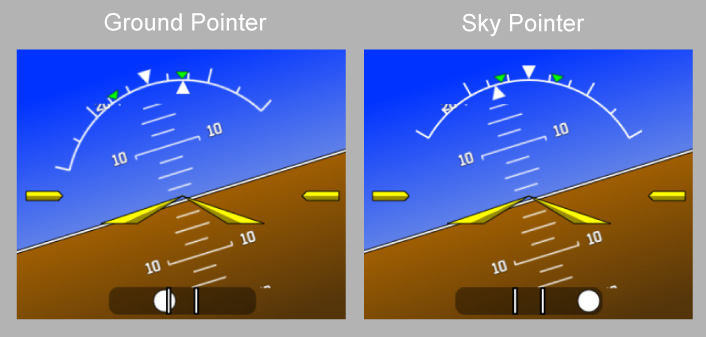
| roll‑pointer | 'sky' or 'ground' | Yes (ground) | Whether the roll indicator should be rendered with a Ground Pointer or a Sky Pointer (see below). |
| unusual‑attitude‑chevrons | Boolean | Yes (false) | Whether red chevrons pointing toward the horizon line should be rendered on the pitch ladder at extreme pitch angles. |
A comparison of the two different roll pointer options:
Content
None.
Default Value
<Horizon symbol-color="yellow" roll-arc="true" roll-pointer="ground" unusual-attitude-chevrons="false" />
<AirspeedIndicator>
Defines options related to the PFD airspeed indicator.
Properties
| Scope | Inherits | Singleton | Optional |
|---|---|---|---|
| Instrument or Global | Yes | Yes | Yes |
Attributes
None.
Child Tags
Default Value
<AirspeedIndicator></AirspeedIndicator>
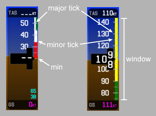
<Scale> (<AirspeedIndicator>)
Defines a PFD airspeed indicator tape scale.
Properties
| Scope | Inherits | Singleton | Optional |
|---|---|---|---|
<AirspeedIndicator> | No | Yes | Yes |
Attributes
| Name | Value | Optional (Default) | Description |
|---|---|---|---|
| min | Number in range (0, ∞) | Yes (20) | The minimum tape speed (knots). |
| max | Number in range (0, ∞) | Yes (999) | The maximum tape speed (knots). |
| window | Number in range (0, ∞) | Yes (70) | The tape window (knots). |
| major‑tick‑interval | Number in range (0, ∞) | Yes (10) | The interval (knots) between major ticks. |
| minor‑tick‑factor | Integer in range [1, ∞) | Yes (2) | The number of minor ticks per major tick. |
Content
None.
Default Value
<Scale min="20" max="999" window="70" major-tick-interval="10" minor-tick-factor="2" />
<ColorRanges>
Defines color ranges for a PFD airspeed indicator tape.
Properties
| Scope | Inherits | Singleton | Optional |
|---|---|---|---|
<AirspeedIndicator> | No | Yes | Yes |
Attributes
None.
Child Tags
Default Value
<ColorRanges>
  <ColorRange width="Full" color="Red">
    <Minimum><!-- Value of the tape scale minimum speed. --></Minimum>
    <Maximum>VS0</Maximum>
  </ColorRange>
  <ColorRange width="Full" color="White">
    <Minimum>VS0</Minimum>
    <Maximum>VFe</Maximum>
  </ColorRange>
  <ColorRange width="Half" color="Green">
    <Minimum>VS1</Minimum>
    <Maximum>VFe</Maximum>
  </ColorRange>
  <ColorRange width="Full" color="Green">
    <Minimum>VFe</Minimum>
    <Maximum>VNo</Maximum>
  </ColorRange>
  <ColorRange width="Full" color="Yellow">
    <Minimum>VNo</Minimum>
    <Maximum>VNe</Maximum>
  </ColorRange>
  <ColorRange width="Full" color="BarberPole">
    <Minimum>VNe</Minimum>
    <Maximum><!-- Value of the tape scale maximum speed. --></Maximum>
  </ColorRange>
</ColorRanges>
<ColorRange>
Defines a single color range for a PFD airspeed indicator tape.
Properties
| Scope | Inherits | Singleton | Optional |
|---|---|---|---|
<ColorRanges> | No | No | Yes |
Attributes
| Name | Value | Optional (Default) | Description |
|---|---|---|---|
| width | 'Full' or 'Half' | No | The width of the color range. |
| color | 'Red', 'Yellow', 'White', 'Green', or 'BarberPole' | No | The color of the color range. |
Child Tags
<Minimum>- Defines the minimum speed of the color range as its content using a
<Speed>tag or a numeric operator on<Speed>tags.
- Defines the minimum speed of the color range as its content using a
<Maximum>- Defines the maximum speed of the color range as its content using a
<Speed>tag or a numeric operator on<Speed>tags.
- Defines the maximum speed of the color range as its content using a
Default Value
None.
<TrendVector> (<AirspeedIndicator>)
Defines how the trend vector of a PFD airspeed indicator is rendered.
Properties
| Scope | Inherits | Singleton | Optional |
|---|---|---|---|
<AirspeedIndicator> | No | Yes | Yes |
Attributes
| Name | Value | Optional (Default) | Description |
|---|---|---|---|
| lookahead | Number | Yes (6) | The lookahead time (seconds) of the trend vector. |
Content
None.
Default Value
<TrendVector lookahead="6" />
<VSpeedBugs>
Defines the V-speed bugs that appear on a PFD airspeed indicator.
The order of bugs defined in this tag affects the layering order of the rendered bugs. If a bug A is defined after bug B (in tree order), then bug A will be rendered on top of bug B when they overlap.
Properties
| Scope | Inherits | Singleton | Optional |
|---|---|---|---|
<AirspeedIndicator> | No | Yes | Yes |
Attributes
None.
Child Tags
Default Value
<VSpeedBugs>
  <Bug name="glide" label="G" />
  <Bug name="r" label="R" />
  <Bug name="x" label="X" />
  <Bug name="y" label="Y" />
</VSpeedBugs>
<Bug> (<VSpeedBugs>)
Defines a single V-speed bug that appears on a PFD airspeed indicator.
Properties
| Scope | Inherits | Singleton | Optional |
|---|---|---|---|
<VSpeedBugs> | No | No | Yes |
Attributes
| Name | Value | Optional (Default) | Description |
|---|---|---|---|
| name | String | No | The name of the V-speed displayed by the bug, as defined by a <VSpeed> tag. |
| label | String | No | The label text to display on the bug. |
For bugs that frequently overlap one another, you can prefix their labels with varying amounts of leading spaces to allow the label text of all bugs to be visible even when they overlap.
Content
None.
Default Value
None.
<SpeedAlerts>
Defines thresholds for overspeed and underspeed alerts on a PFD airspeed indicator.
If either the overspeed or underspeed alert threshold is not defined, then that alert will never trigger.
Properties
| Scope | Inherits | Singleton | Optional |
|---|---|---|---|
<AirspeedIndicator> | No | Yes | Yes |
Attributes
None.
Child Tags
Default Value
<SpeedAlerts></SpeedAlerts>
<Overspeed>
Defines the threshold for the overspeed alert on a PFD airspeed indicator.
Properties
| Scope | Inherits | Singleton | Optional |
|---|---|---|---|
<SpeedAlerts> | No | Yes | Yes |
Attributes
None.
Content
A <Speed> tag or a numeric operator on <Speed> tags.
Default Value
None.
<Underspeed>
Defines the threshold for the underspeed alert on a PFD airspeed indicator.
Properties
| Scope | Inherits | Singleton | Optional |
|---|---|---|---|
<SpeedAlerts> | No | Yes | Yes |
Attributes
None.
Content
A <Speed> tag or a numeric operator on <Speed> tags.
Default Value
None.
<Speed>
Defines an airspeed value. Can be used as the operand of a numeric operator.
The speed can be defined as one of several types, which determine now the numeric value of the speed is interpreted:
- Ias
- Speed is equal to the numeric value as an indicated airspeed (knots).
- Mach
- Speed is equal to the numeric value as a mach number.
- Tas
- Speed is equal to the numeric value as a true airspeed (knots).
- Reference
- Speed is equal to the sim reference speed as an indicated airspeed (knots).
- Aoa
- Speed is equal to that which produces a normalized angle of attack (where zero-lift AoA = 0 and critical AoA = 1) equal to the numeric value. If AoA cannot be accurately related to airspeed (e.g. when the airplane is on the ground or when AoA data is not available), the speed will be undefined. It is up to individual consumers of the speed value to determine how to handle an undefined airspeed.
Use numeric operators to define speeds with complex values. For example, we can define a speed equal to the maximum operating speed of an aircraft with Vmo = 280 knots and Mmo = 0.8 as:
<Min>
  <Speed type="Ias">280</Speed>
  <Speed type="Mach">0.8</Speed>
</Min>
Properties
| Scope | Inherits | Singleton | Optional |
|---|---|---|---|
| Generic | No | N/A | N/A |
Attributes
| Name | Value | Optional (Default) | Description |
|---|---|---|---|
| type | 'Ias', 'Mach', 'Tas', 'Reference', or 'Aoa' | No | The type of speed. |
Content
- If
typeis Ias, Mach, Tas, or Aoa, then one of the following:- Number
- Defines the value as a constant.
<LookupTable>- Defines the value as a one-dimensional lookup table that looks it up from pressure altitude (feet).
- Number
- If
typeis Reference, then:- Sim reference speed key
- Defines the value as a sim reference speed, as defined in the
[REFERENCE SPEEDS]section offlight_model.cfg. The possible keys are:BestGlideVappVFeVmcVMaxVMinVNeVNoVrVS0VS1VxVyVyse
- Defines the value as a sim reference speed, as defined in the
- Sim reference speed key
<Vsi>
Defines options related to the PFD vertical speed indicator.
Properties
| Scope | Inherits | Singleton | Optional |
|---|---|---|---|
| Instrument or Global | Yes | Yes | Yes |
Attributes
None.
Child Tags
Default Value
<Vsi></Vsi>
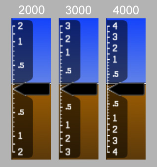
<Scale> (<Vsi>)
Defines a PFD vertical speed indicator scale.
Properties
| Scope | Inherits | Singleton | Optional |
|---|---|---|---|
<Vsi> | No | Yes | Yes |
Attributes
| Name | Value | Optional (Default) | Description |
|---|---|---|---|
| max | 2000, 3000, or 4000 | Yes (2000) | The maximum nominal absolute vertical speed (feet per minute). |
Content
None.
Default Value
<Scale max="2000" />
<BingMapOpt>
Defines options related to reducing the number of Bing map instances used by a G3X Touch GDU.
By default (i.e. without any of the optimizations applied by this tag), each G3X Touch GDU uses four Bing map instances. The maximum number of instances allotted by the sim is ten.
Properties
| Scope | Inherits | Singleton | Optional |
|---|---|---|---|
| Instrument or Global | No | Yes | Yes |
Attributes
| Name | Value | Optional (Default) | Description |
|---|---|---|---|
| disable‑pfd‑maps | Boolean | Yes (false) | Whether to disable the PFD Inset Map and the PFD Map Page. Reduces the number of Bing map instances used by a GDU by 1. |
| disable‑svt | Boolean | Yes (false) | Whether to disable the PFD SVT (synthetic vision) display. Reduces the number of Bing map instances used by a GDU by 1. |
Content
None.
Default Value
<BingMapOpt disable-pfd-maps="false" disable-svt="false" />
<LookupTable>
Defines an N-dimensional linearly interpolated lookup table.
Properties
| Scope | Inherits | Singleton | Optional |
|---|---|---|---|
| Generic | No | N/A | N/A |
Attributes
| Name | Value | Optional (Default) | Description |
|---|---|---|---|
| dimensions | Integer in range [1, ∞) | No | The table's dimension count. |
Content
An array of breakpoints, in standard JSON format. Each breakpoint is a number array of length dimensions + 1, where the value at index 0 is the breakpoint output, and the values at indexes i = 1...dimension are the breakpoint inputs in each dimension i.